This Raspberry Pi based NAS was built for my comparison with the Asustor Drivestor 4. Rather than cover the comparison and build in a single lengthy post, I have separated the build portion of the Raspberry Pi NAS to make it easier for you to build your own NAS along with me.
Here’s my video of the build and comparison, read on for the write-up and build guide:
What You Need To Build Your Own Raspberry Pi NAS
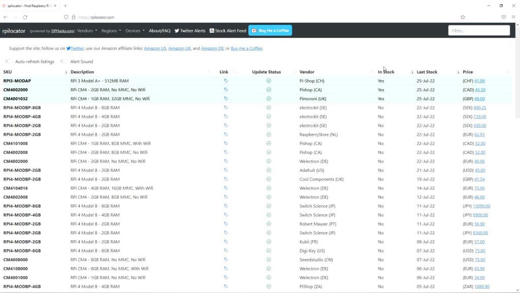
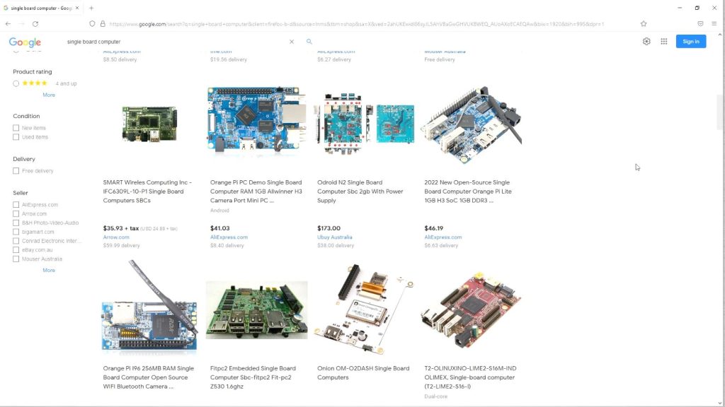
- Raspberry Pi 4B – Buy Here
- 2 x 6TB Seagate Ironwolf NAS Drives – Buy Here
- 2 x USB 3.0 to SATA Adaptors – Buy Here
- 32GB MicroSD Card – Buy Here
- 5V Raspberry Pi Power Supply – Buy Here
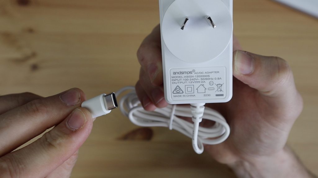
- 12V 5A Power Supply – Buy Here
- 12V Barrel Jack Splitter – Buy Here
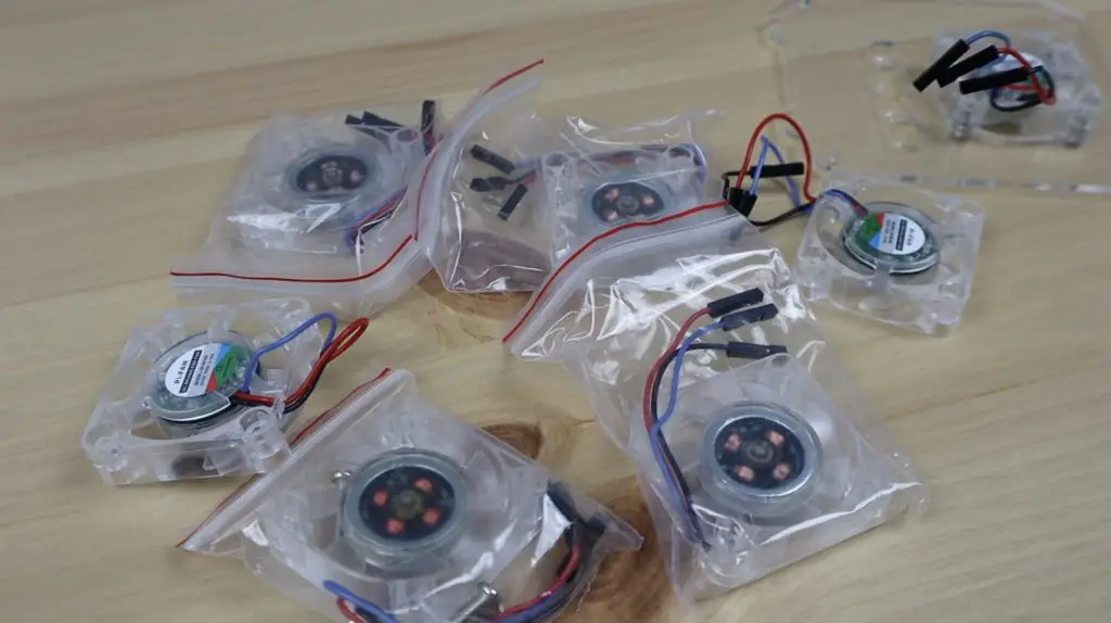
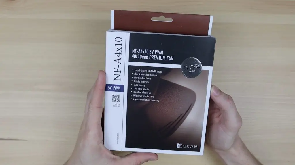
- 60mm Fan – Buy Here
- Aluminium Heatsink – Buy Here
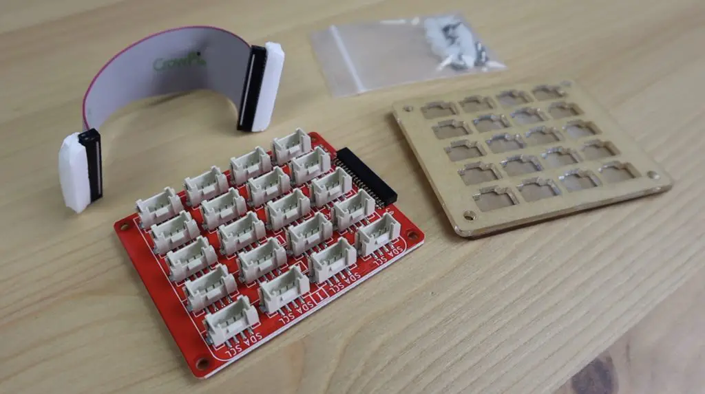
- 0.96” I2C OLED Display – Buy Here
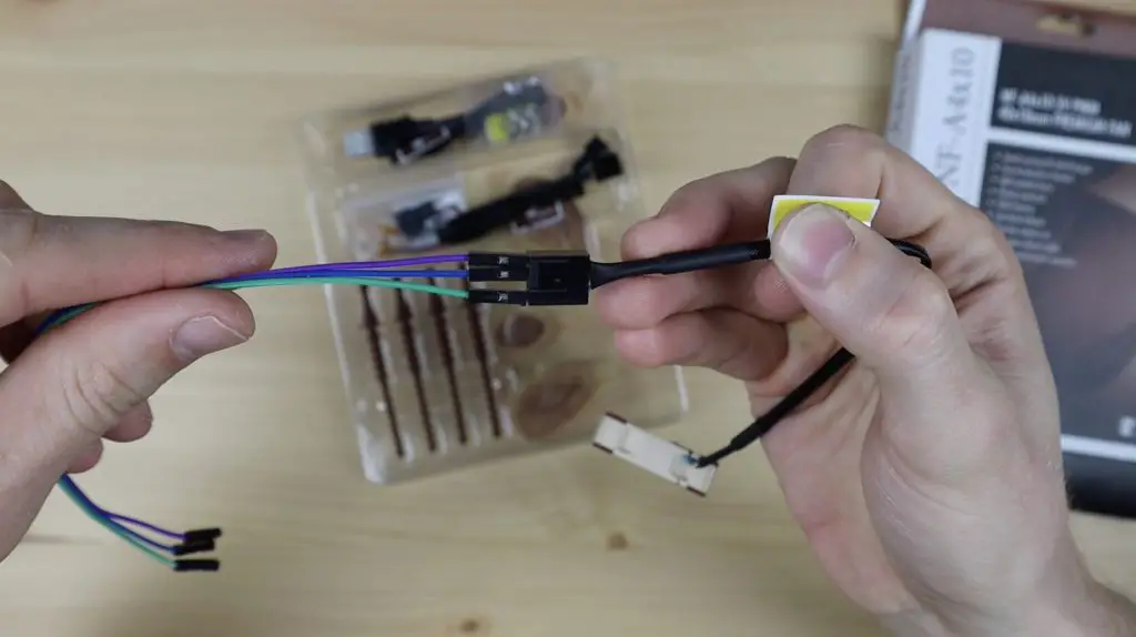
- 4 Wire Jumper Cable – Buy Here
- 3mm Tinted Acrylic Sheets – Buy Here
- M3 Screw Set – Buy Here
- M2.5 Screw Set – Buy Here
- M2.5 x 6mm Brass Standoffs – Buy Here
- M2 Screw Set – Buy Here
- #6-32 UNC Screws – Buy Here
Equipment Used
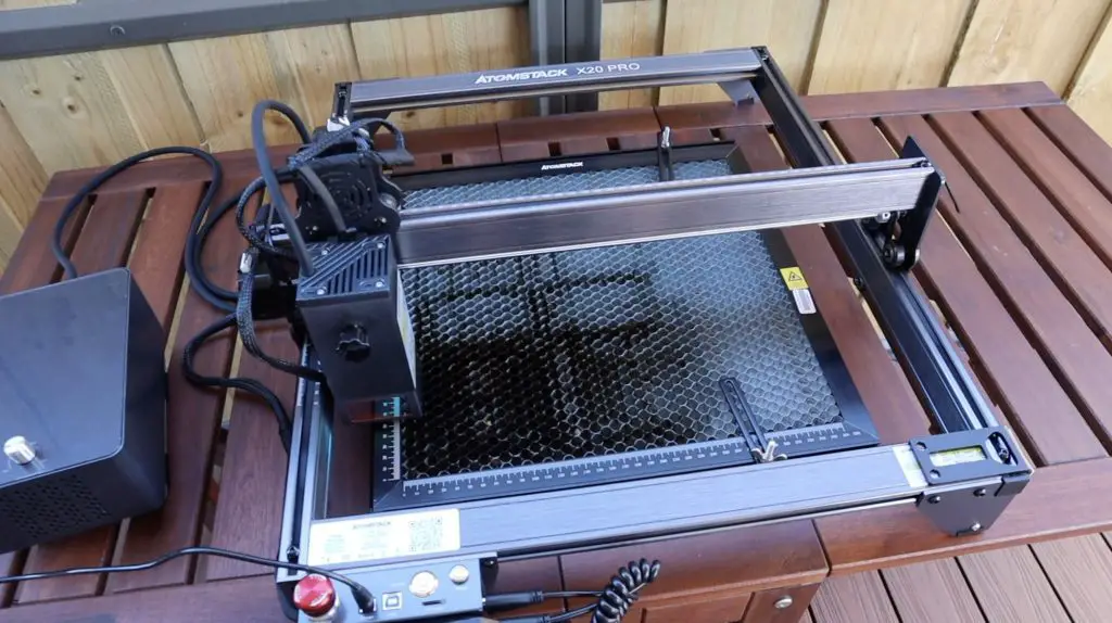
- Gweike Cloud Laser Cutter – Buy Here
- Get $100 off the Gweike Cloud Laser by entering MK100 on checkout
- USB C Screwdriver Set – Buy Here
Some of the above parts are affiliate links. By purchasing products through the above links, you’ll be supporting this channel, at no additional cost to you.
How To Build The Raspberry Pi NAS
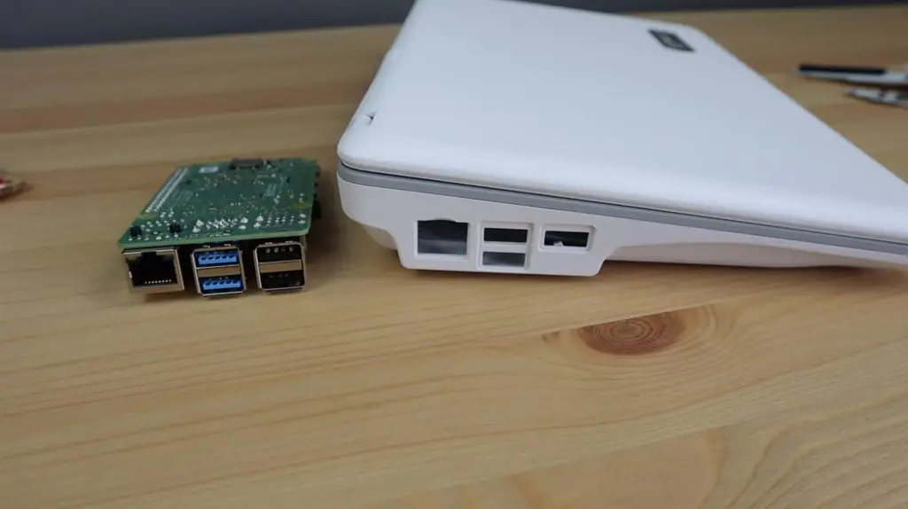
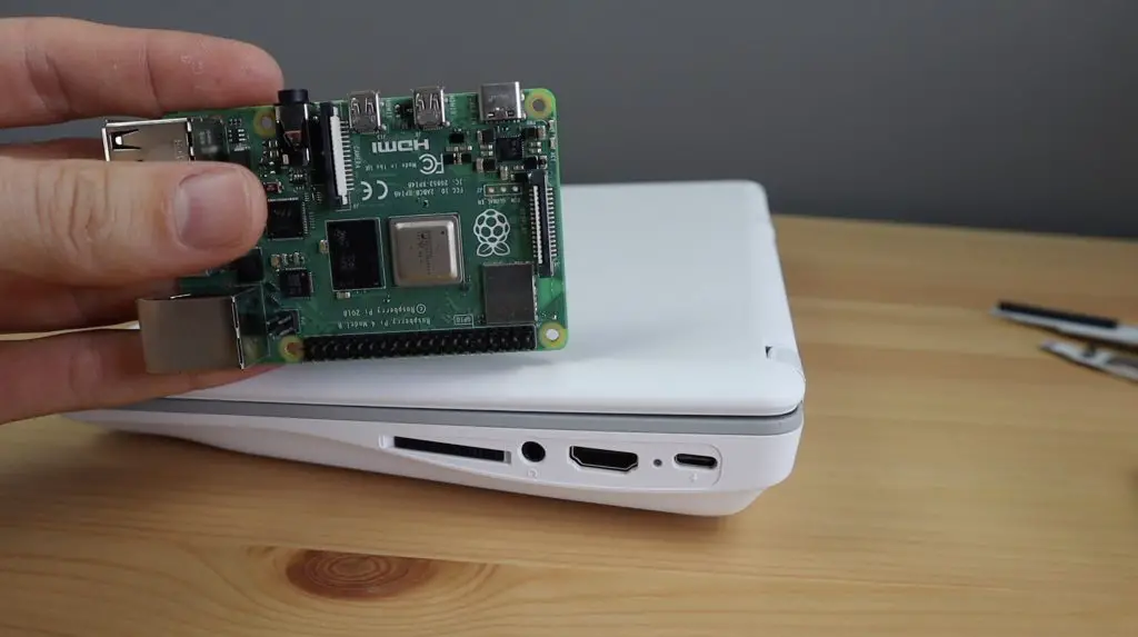
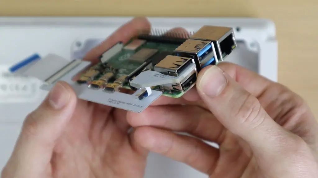
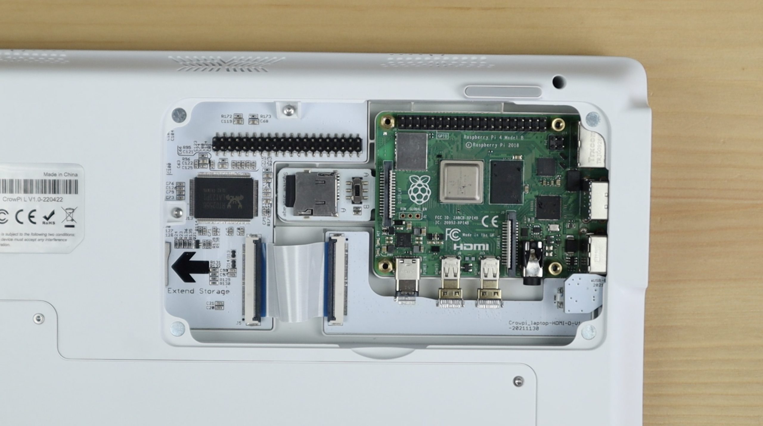
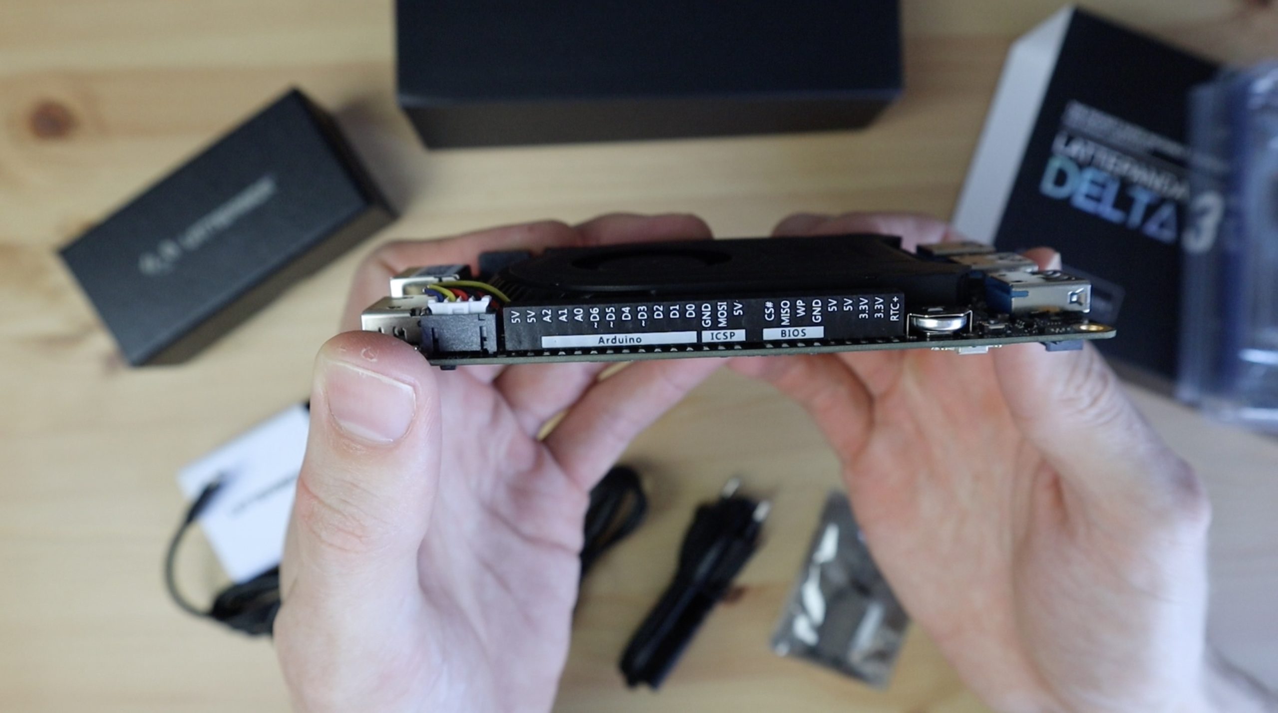
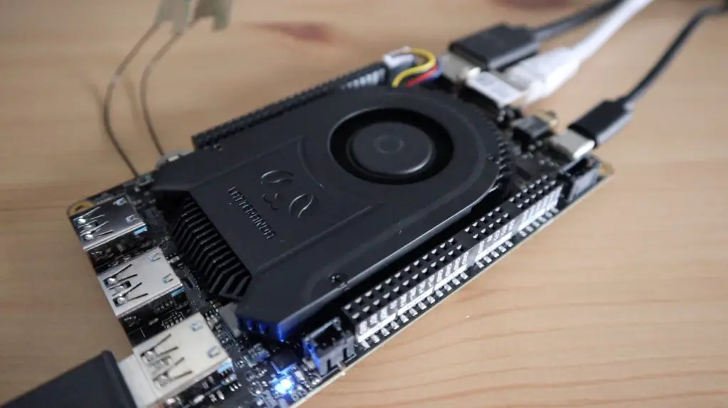
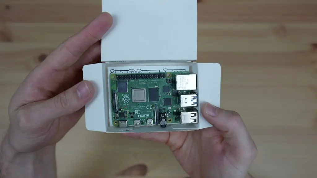
For my Raspberry Pi NAS, I’m going to be using an 8GB Raspberry Pi 4B. This has a 1.5Ghz quad-core ARM Cortex-A72 CPU, 8GB of DDR4 RAM and 32GB of storage through a microSD card. It’s also got 2 USB 3.0 ports which we’ll be able to connect our drives to, 2 USB 2.0 ports for slower devices, and gigabit Ethernet.
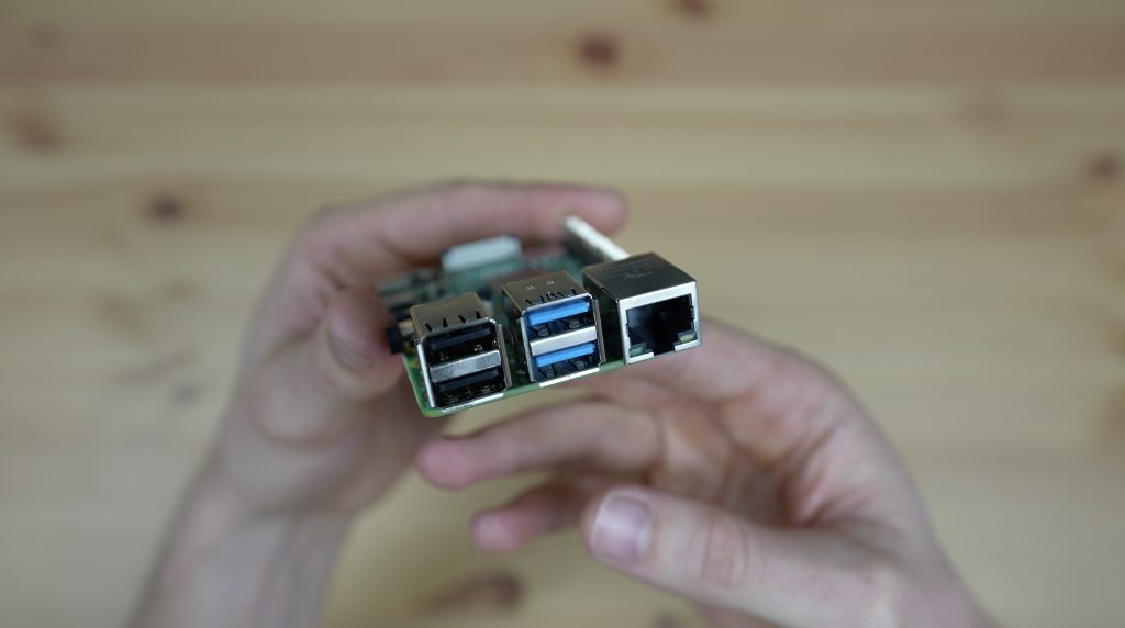
Because we’ve only got two USB 3.0 ports on the Raspberry Pi, I’m only going to connect two 3.5″ SATA NAS drives to it. Alternately we could also use a USB hub as the ports on the Pi all share a PCIe lane anyway, but we’d still be limited to the maximum bandwidth of this lane, which I think is 4 Gbps.
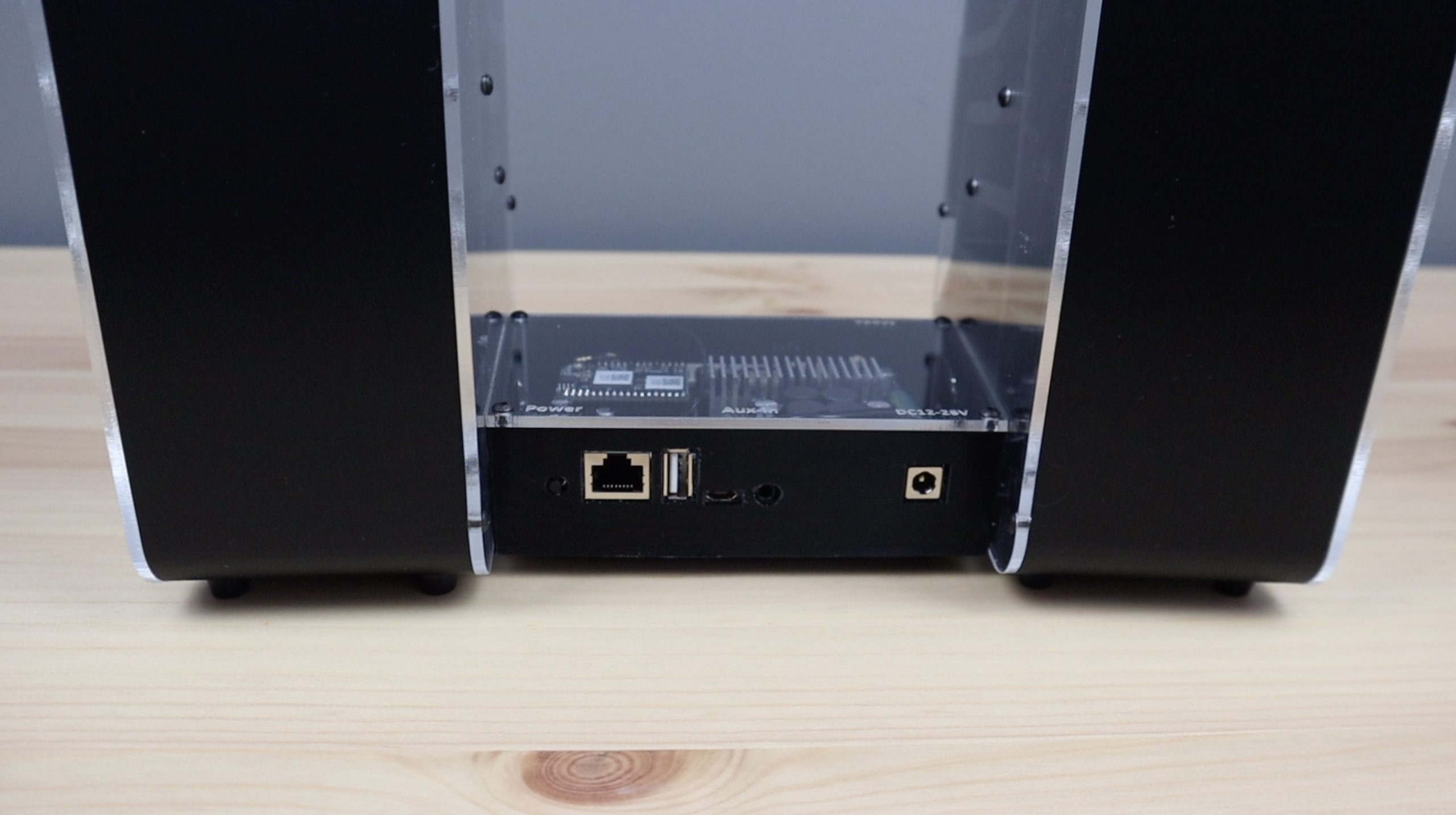
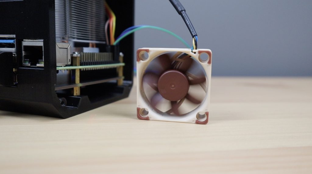
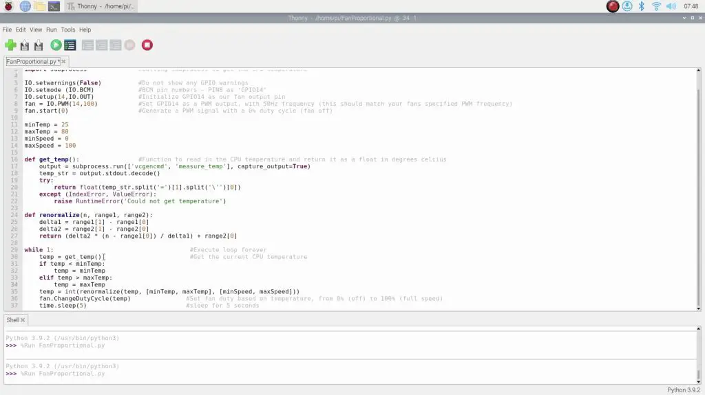
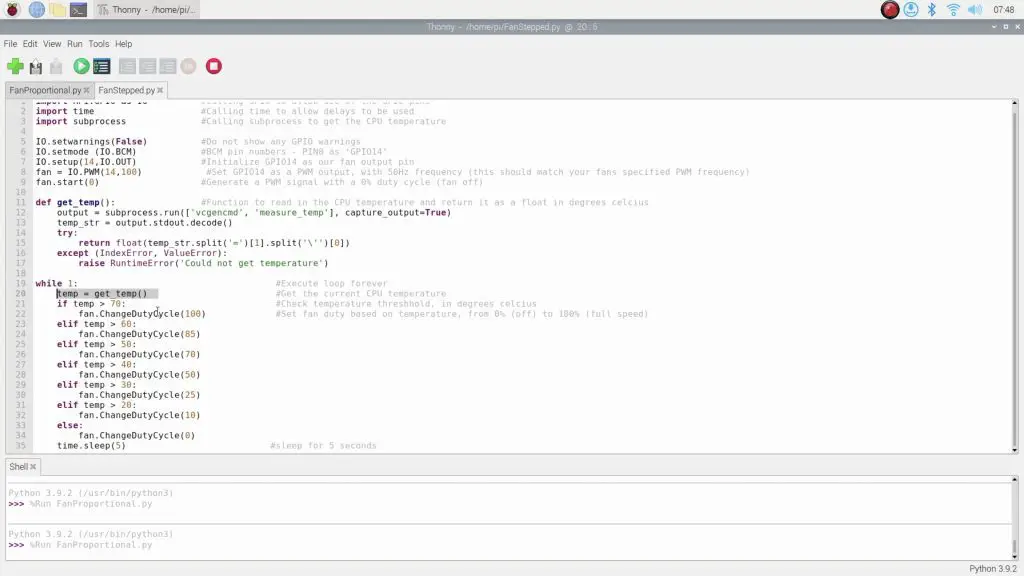
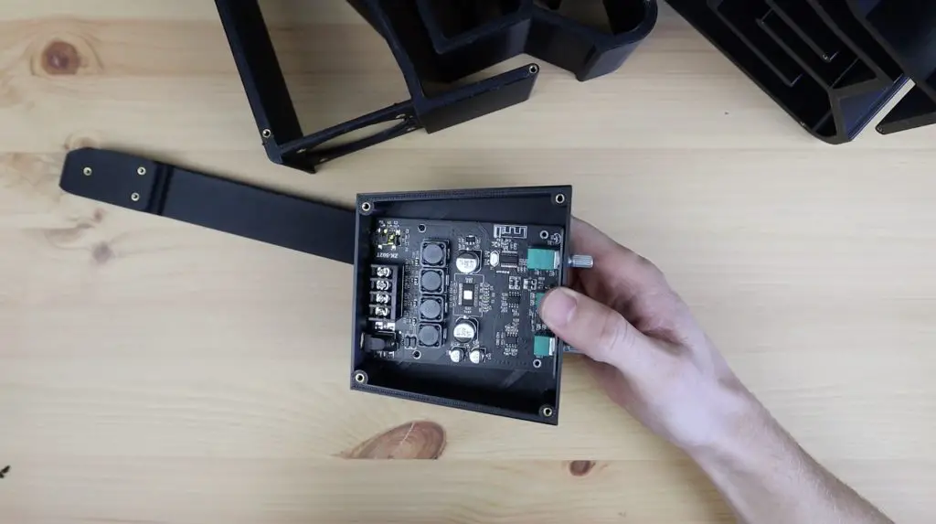
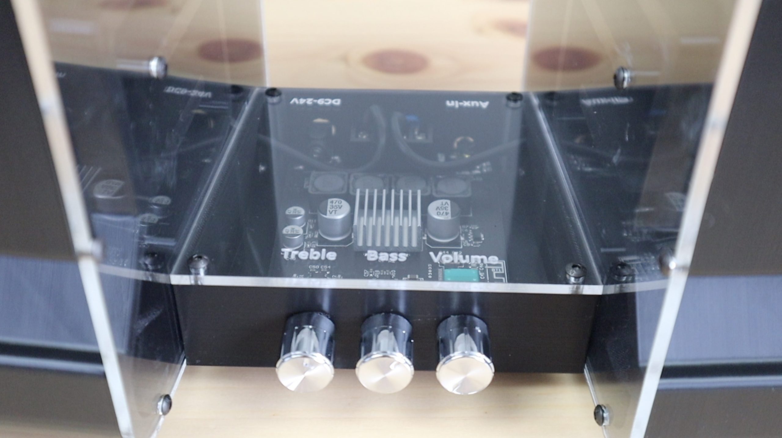
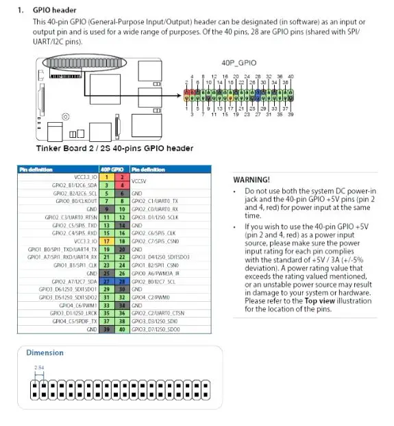
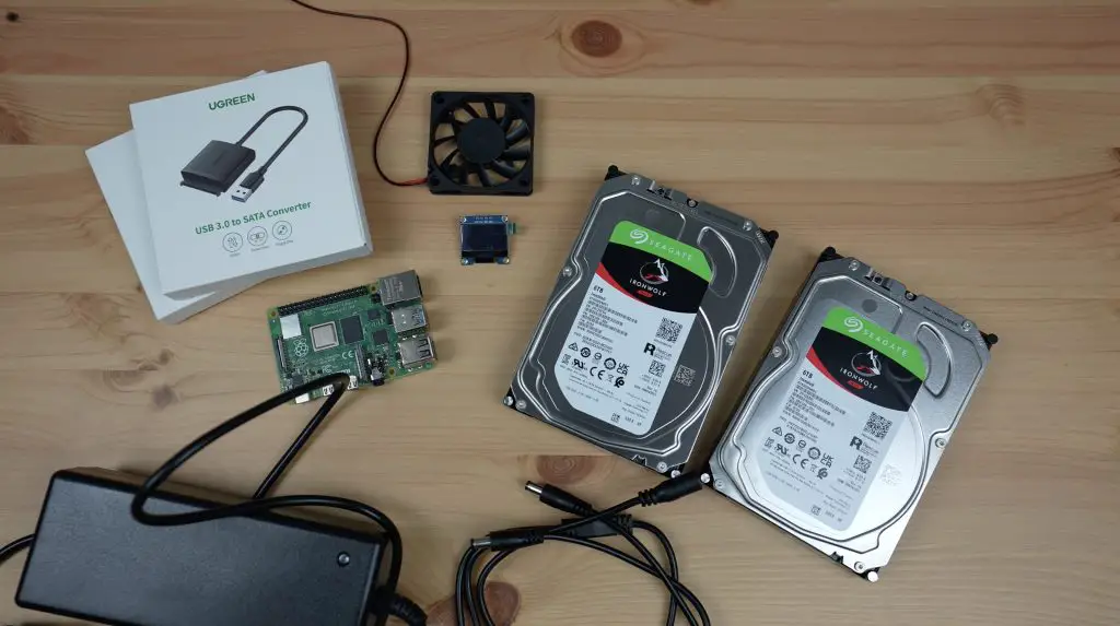
I’m going to use two USB 3.0 to SATA adaptors to connect the drives to my Pi and we’ll need to provide external power to them using a 12V adaptor and a barrel jack splitter. I’ll also need another power supply for the Pi as this runs on 5V. I could power the Pi from the 12V supply as well, but I’d need to add another splitter and a step-down converter from 12V to 5V. I’m going to add a small OLED display which will be used to display some metrics and the NAS’ IP address. And finally, to cool the Pi and drives I’m going to use a 60mm fan which I’ll power from the Pi’s GPIO pins.
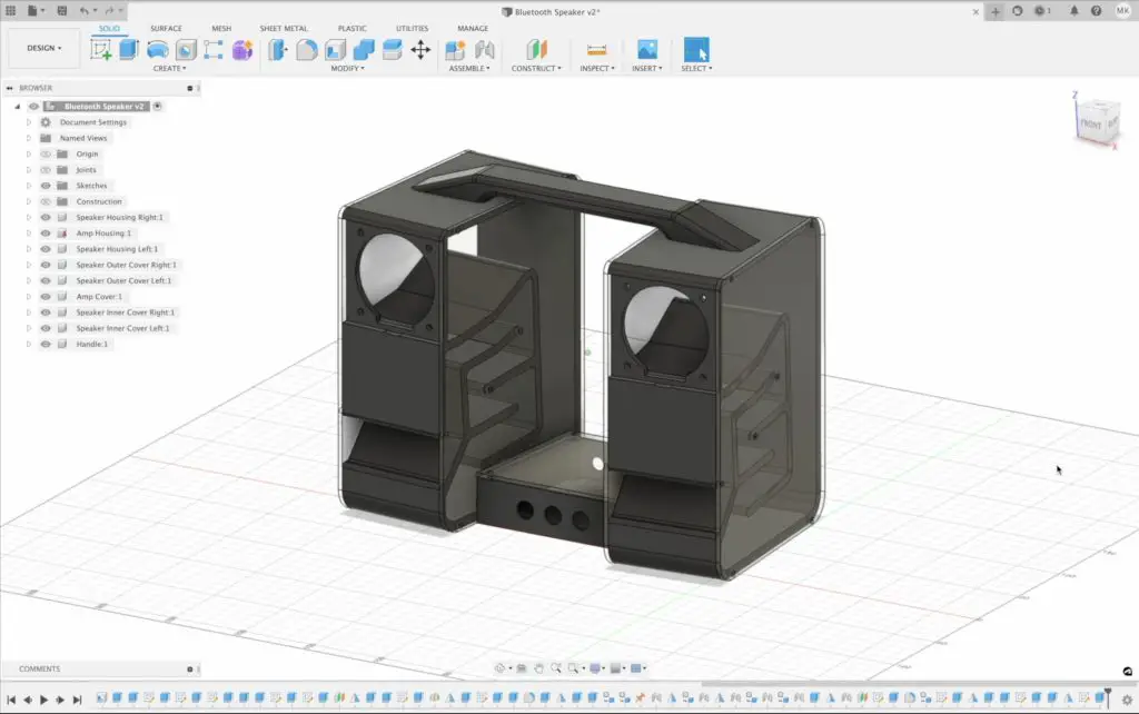
Designing The NAS Enclosure
Now that we’ve got the hardware together, we need to start assembling it, and for that, we need an enclosure. There aren’t a lot of options for a Raspberry Pi NAS, so I’m going to have to make my own.
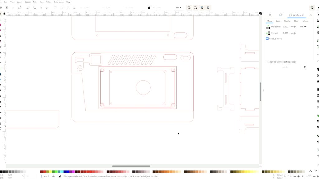
To do that, I’m going to head over to my computer and open up Inkscape. I’ve used Inkscape before for a number of projects, it’s a great open-source package for creating 2D designs for laser cutting.
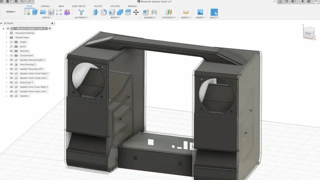
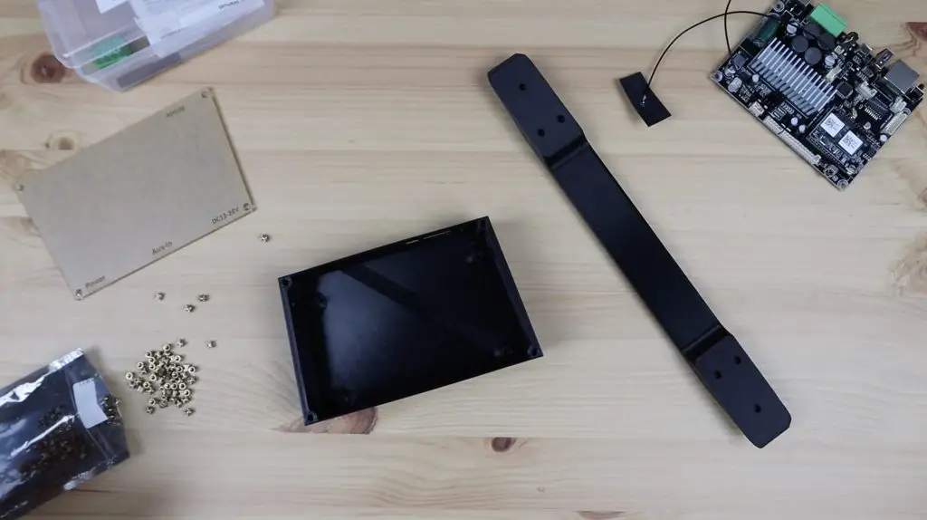
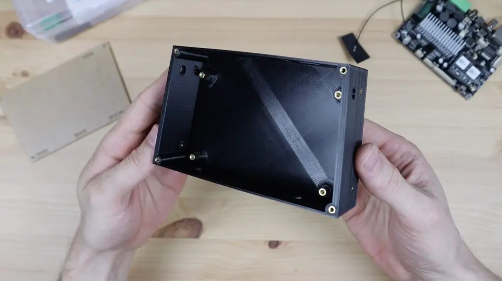
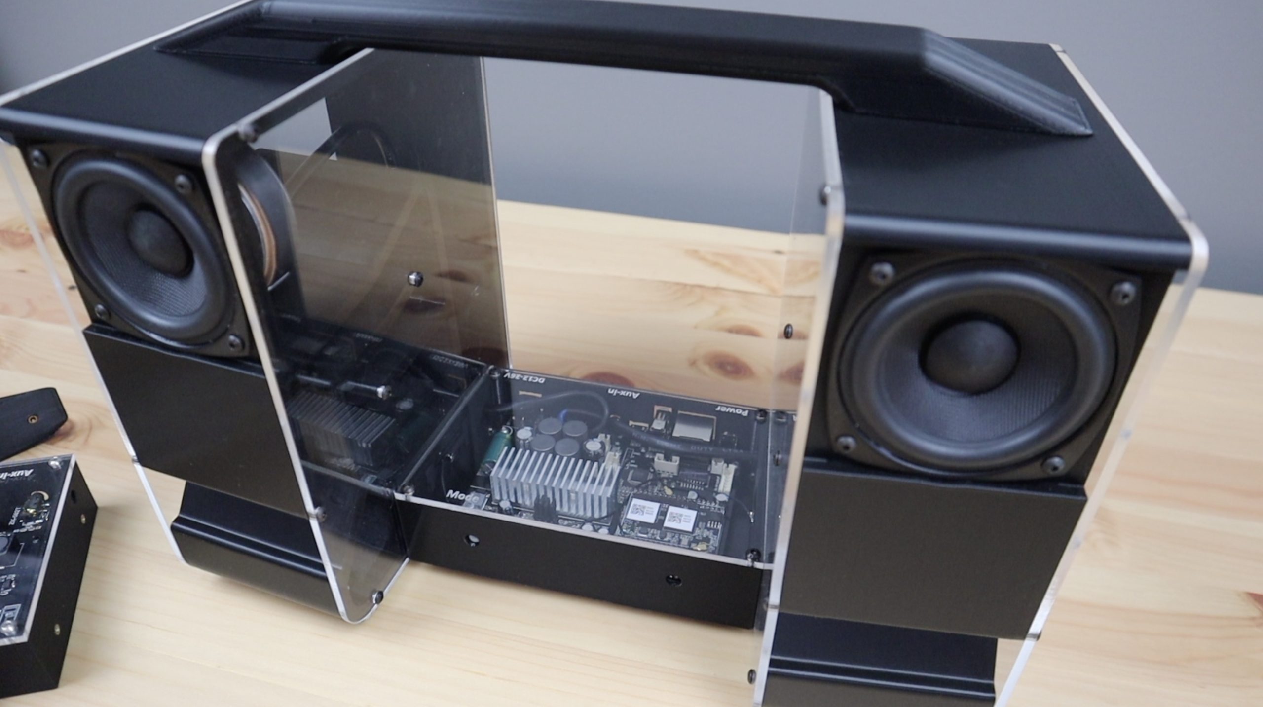
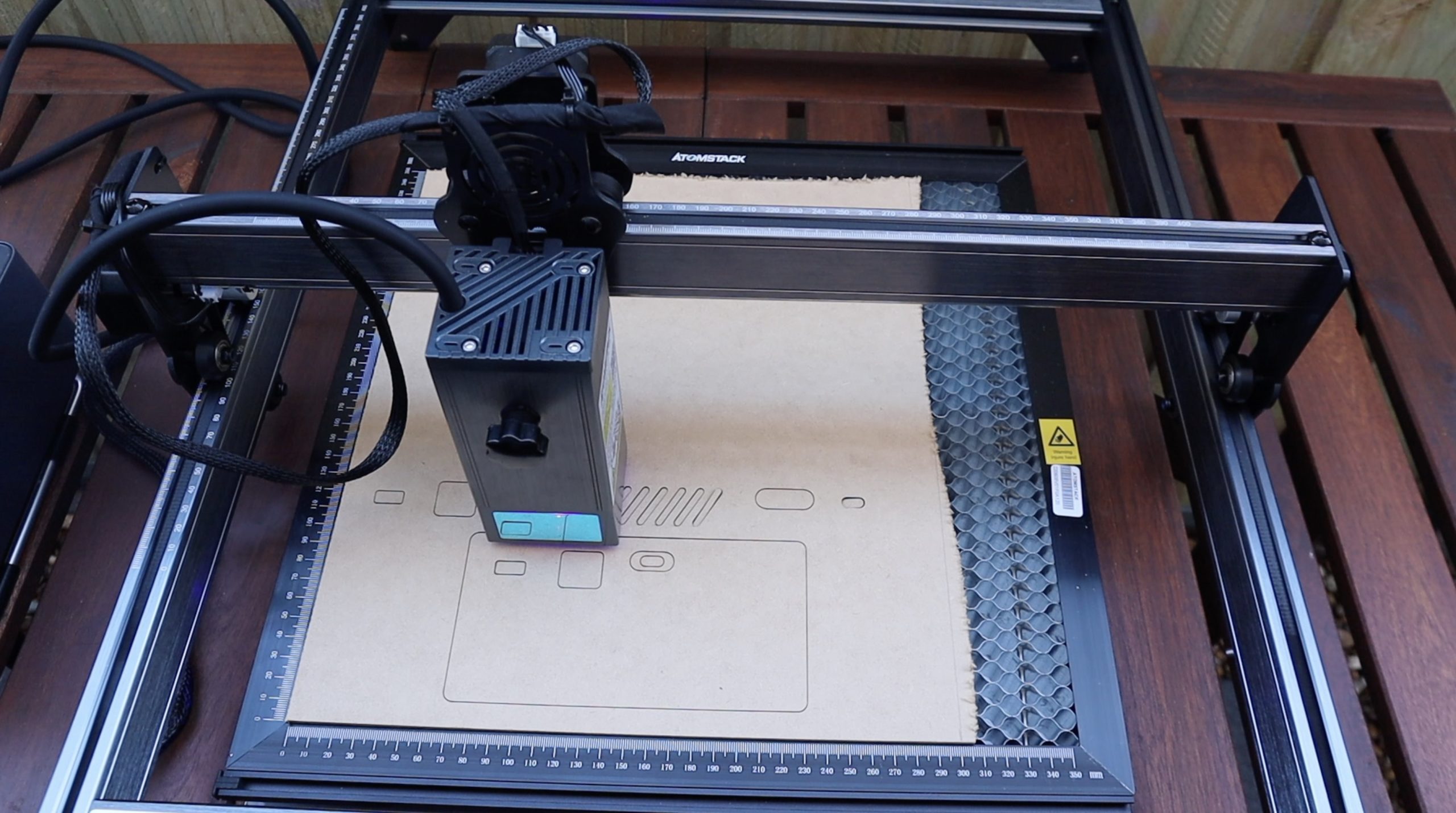
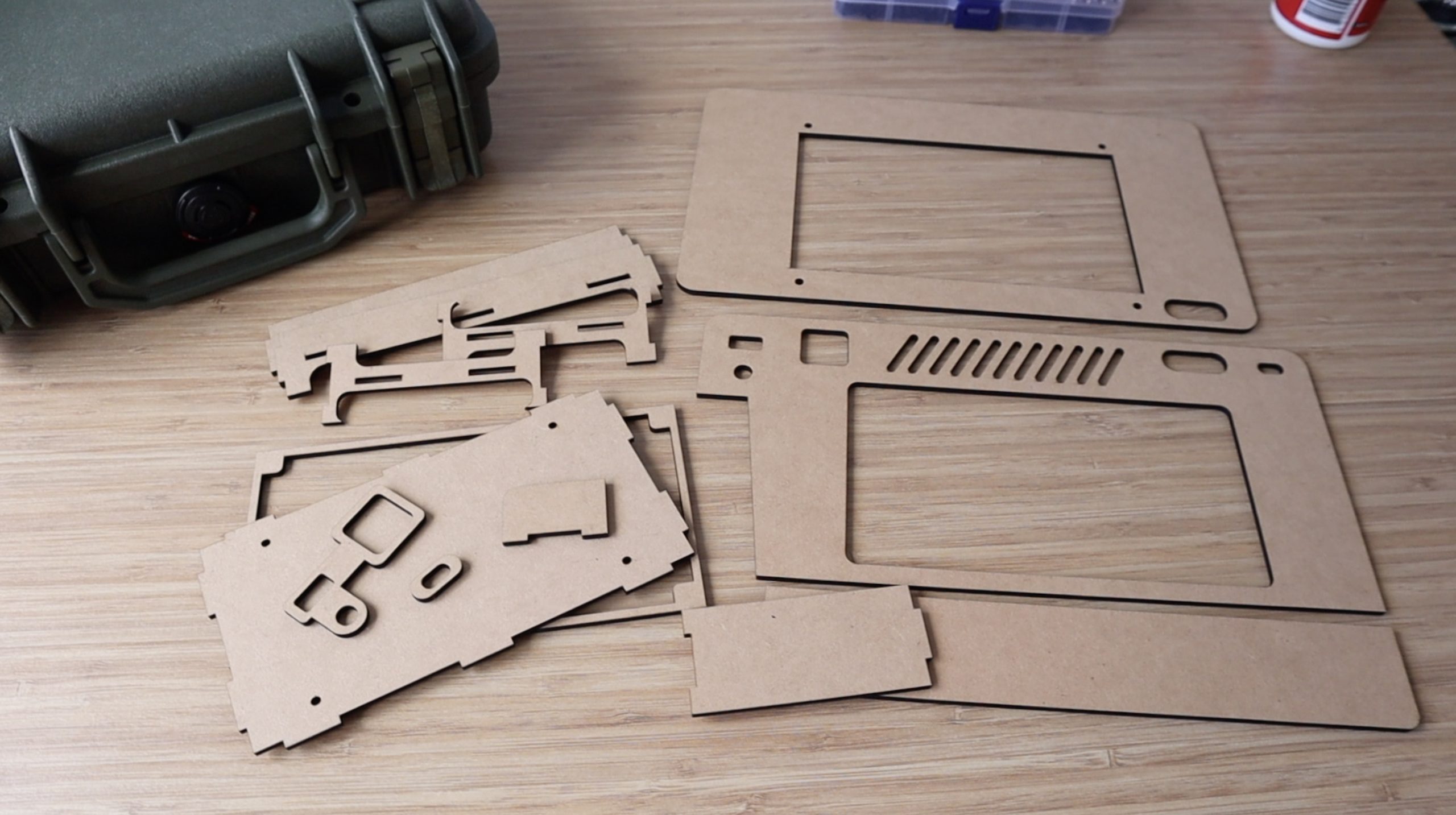
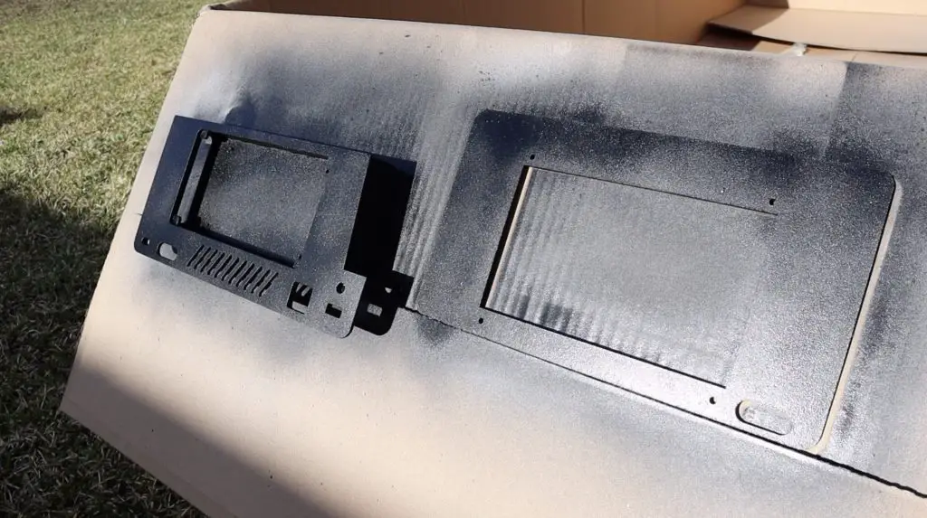
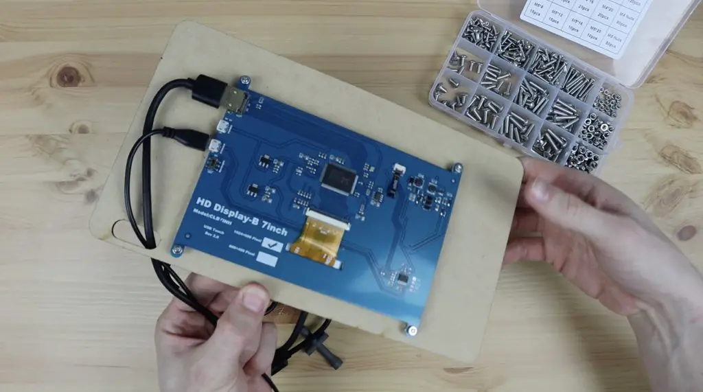
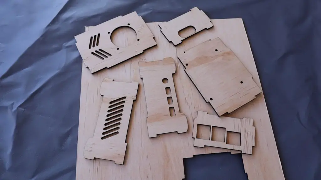
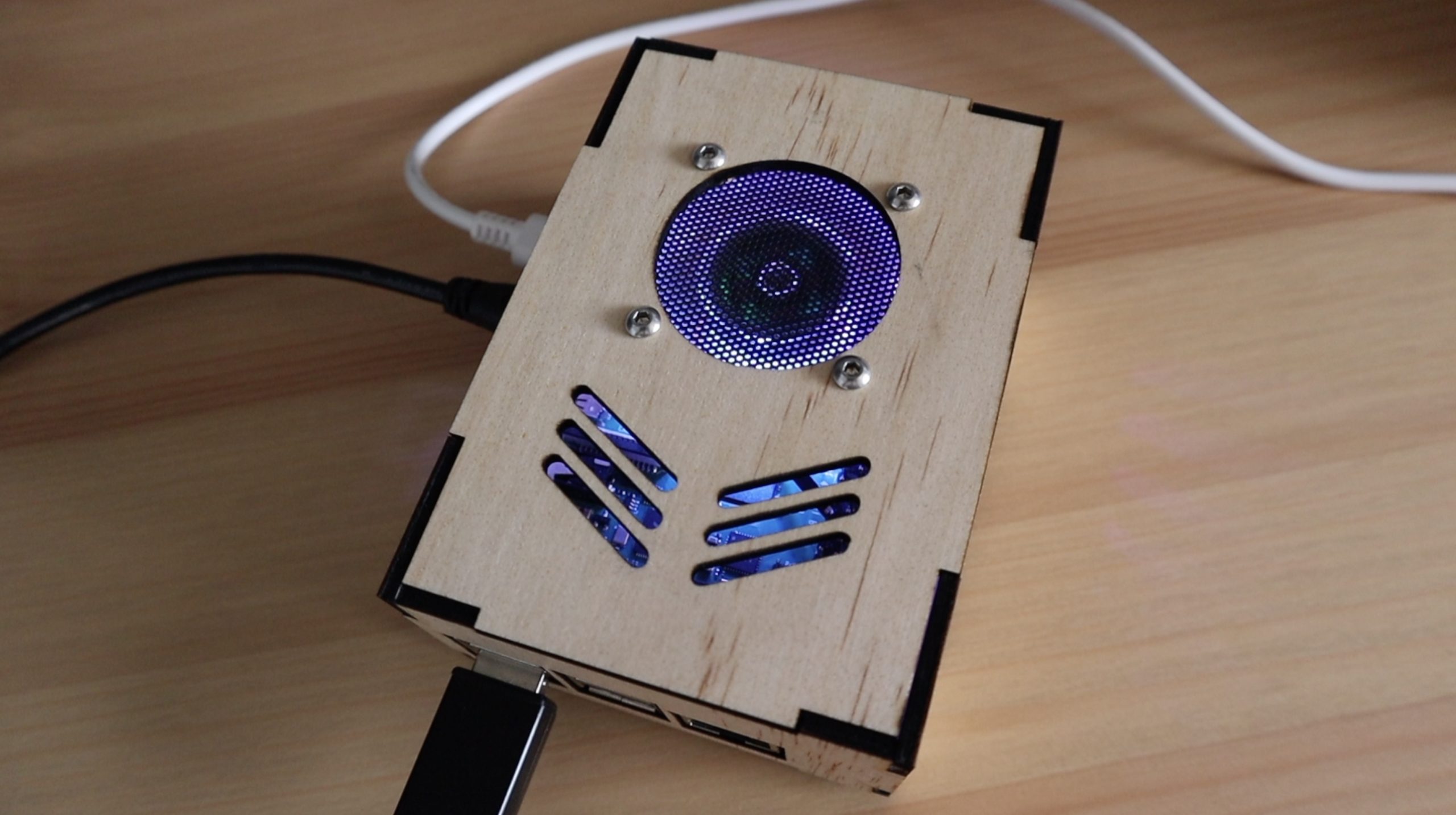
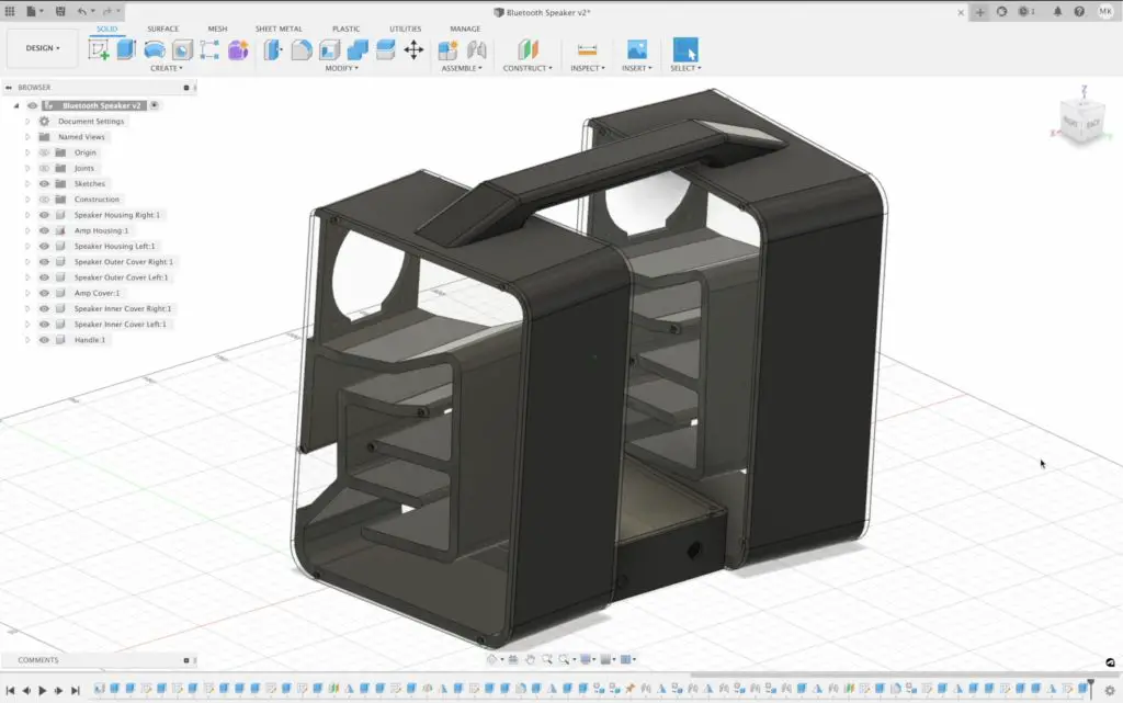
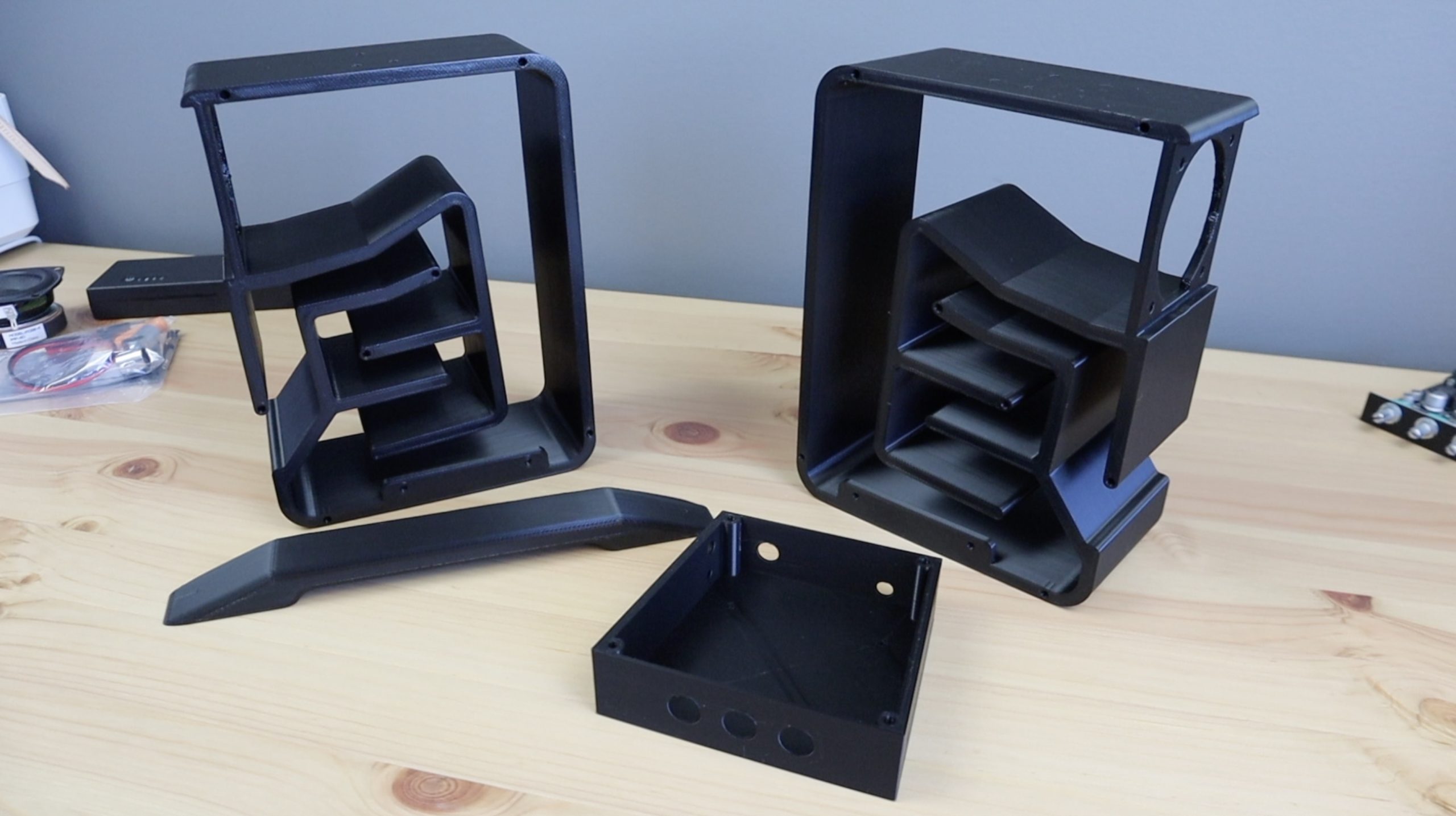
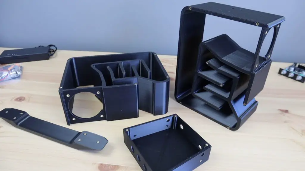
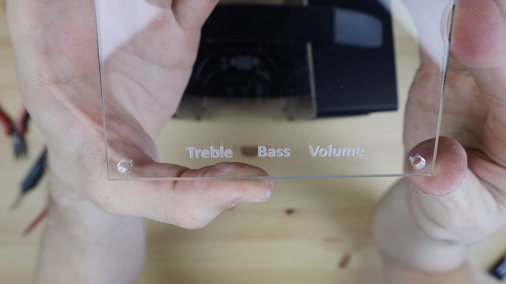
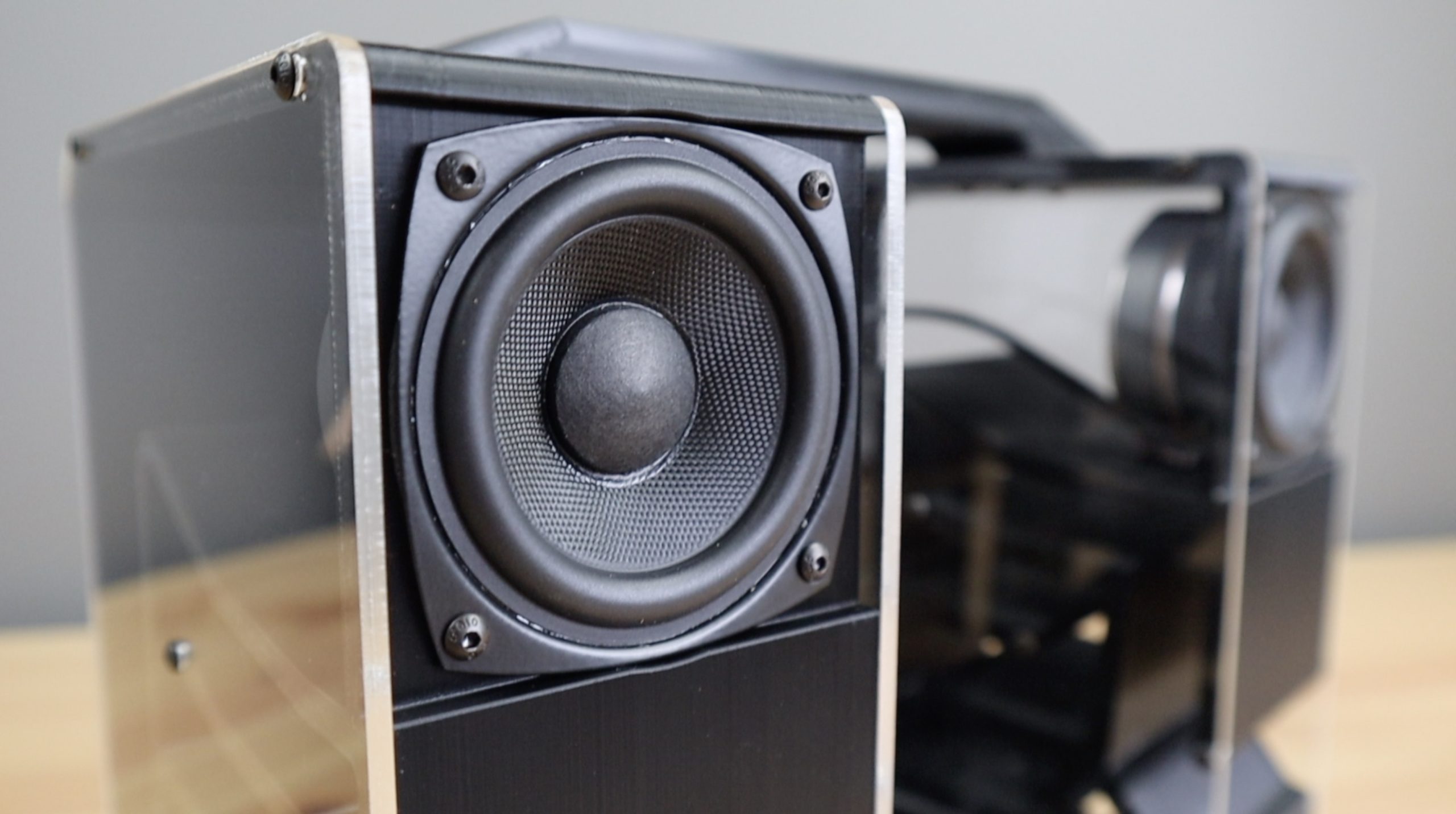
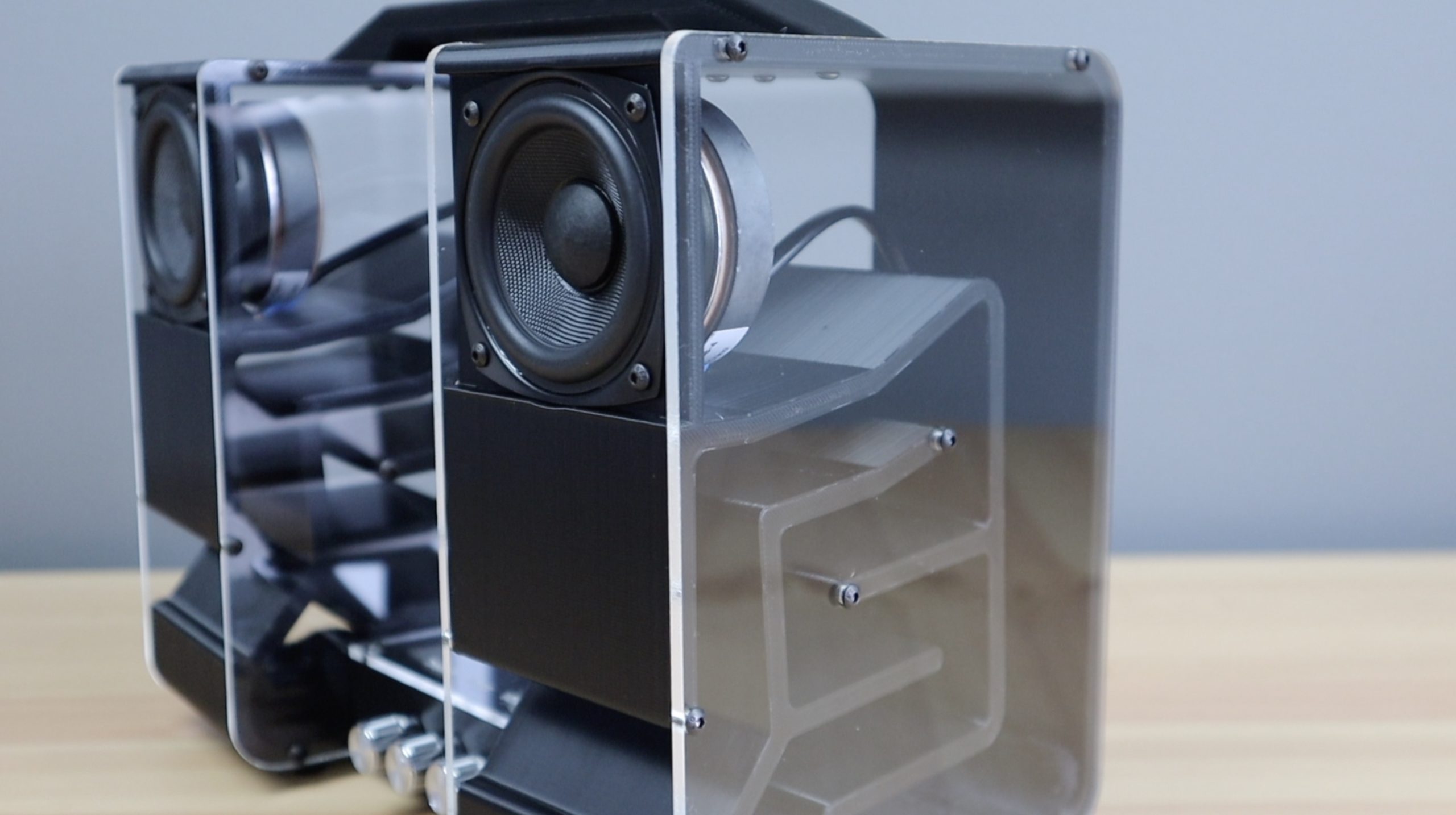
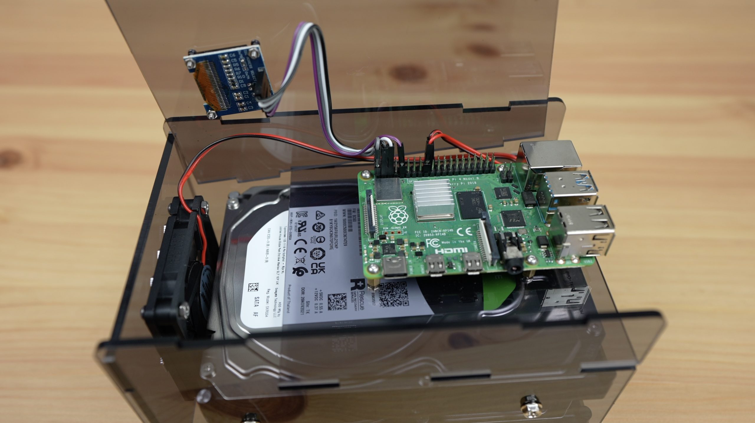
I sketched up the parts I need to hold the drives, the Pi, display and fan – there are two main side panels that attach to the drives and then a front fan panel, a Pi mounting panel and a top cover on which the OLED display is mounted.
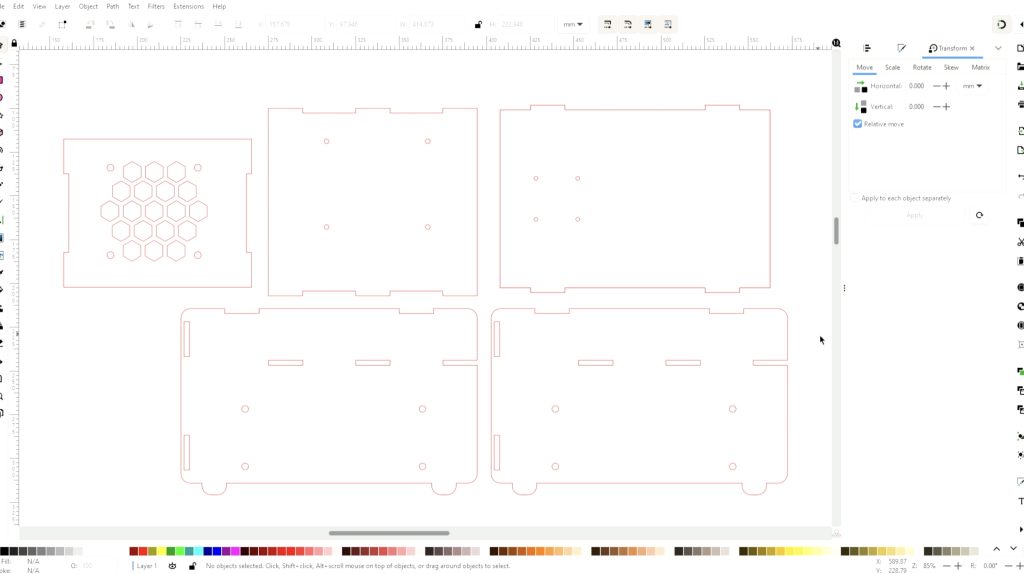
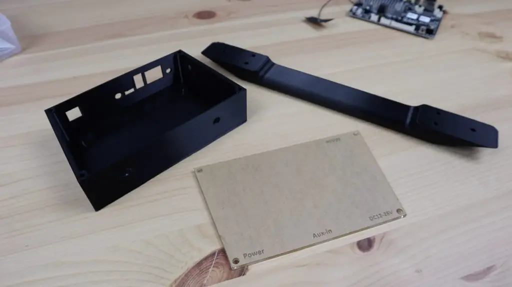
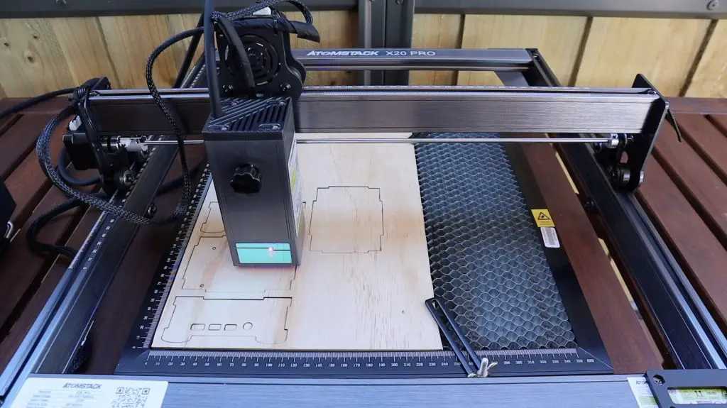
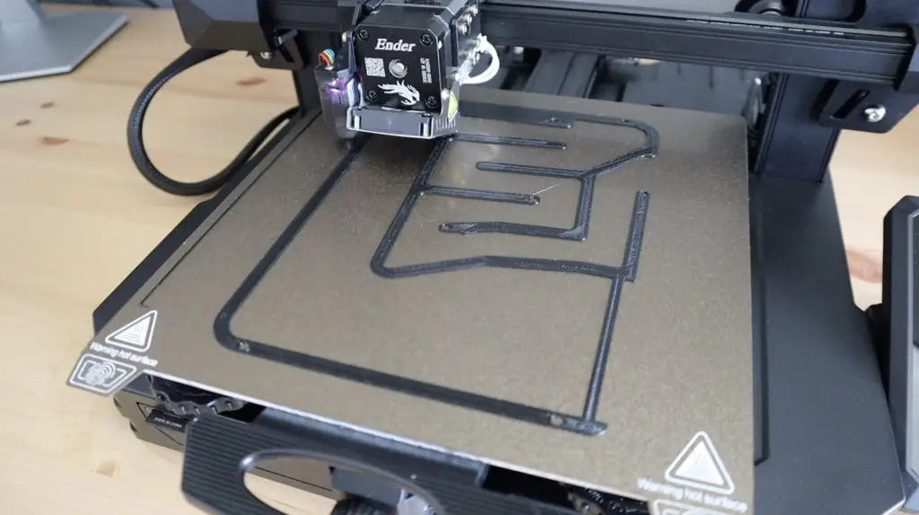
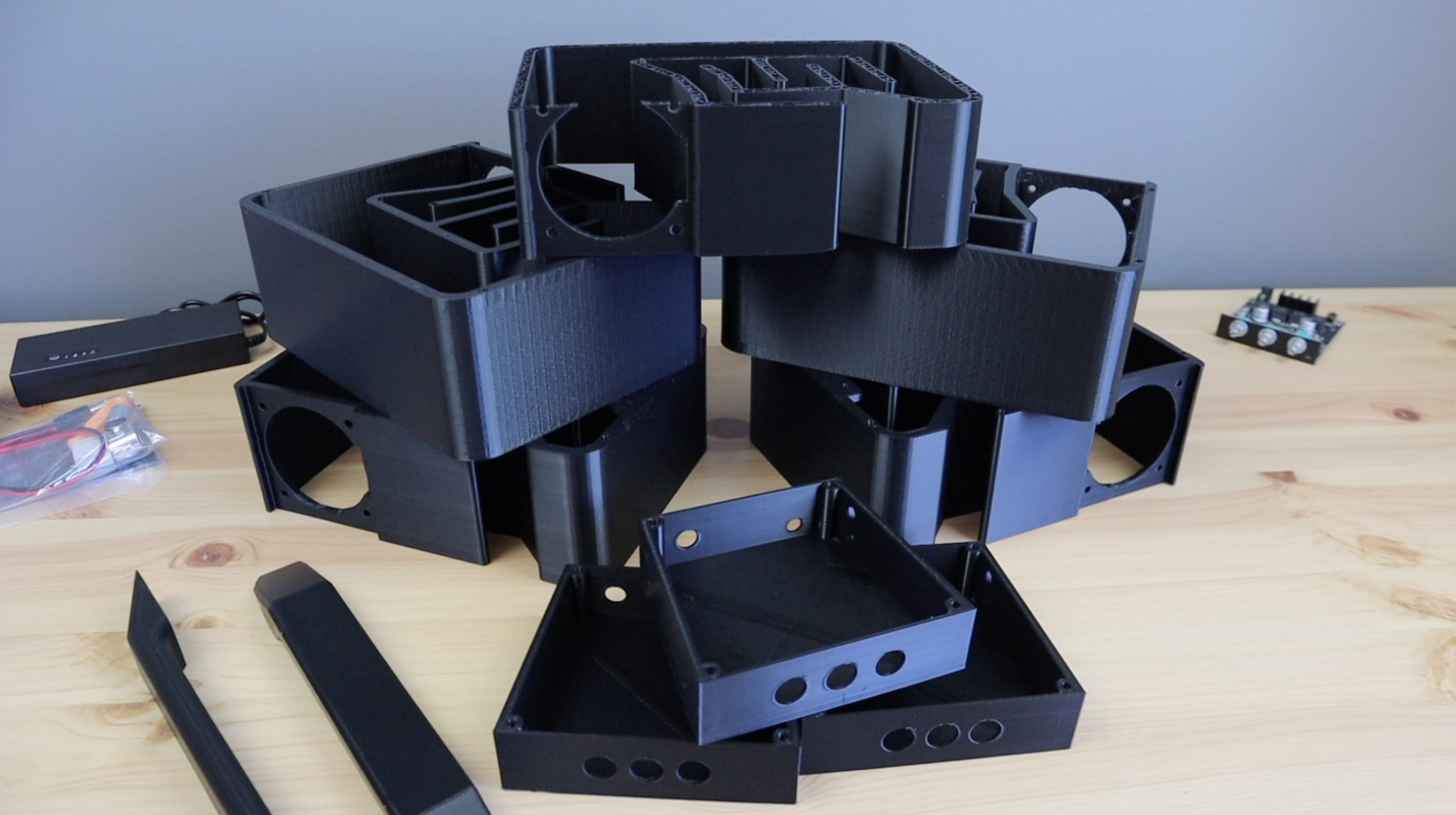
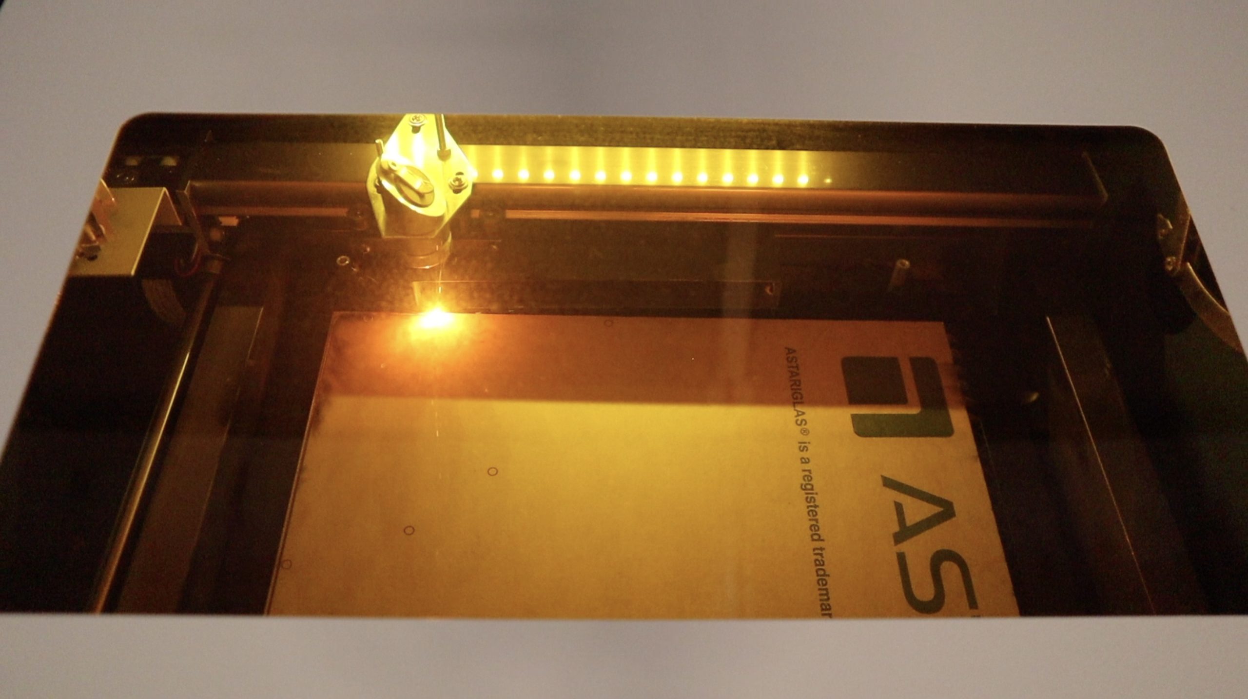
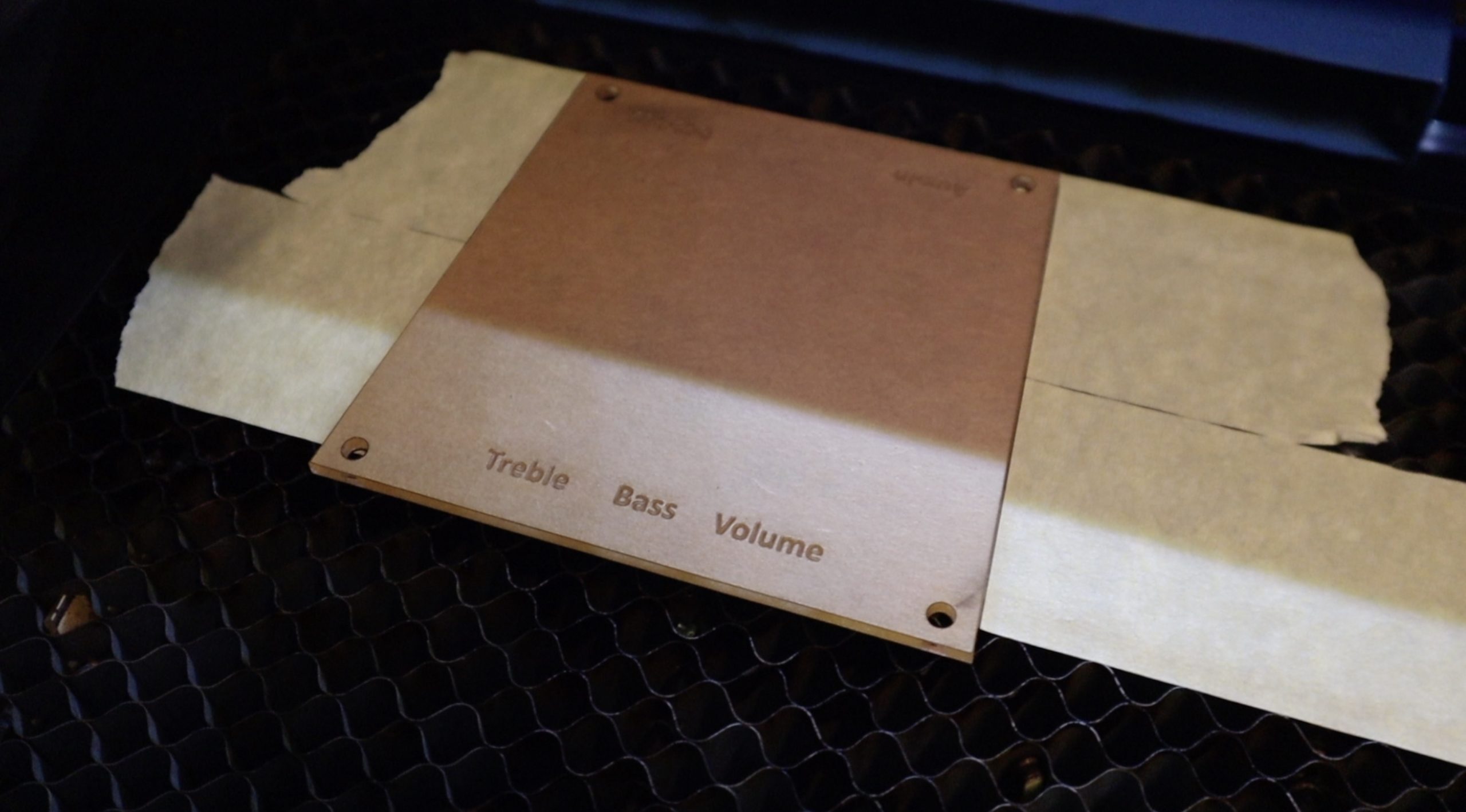
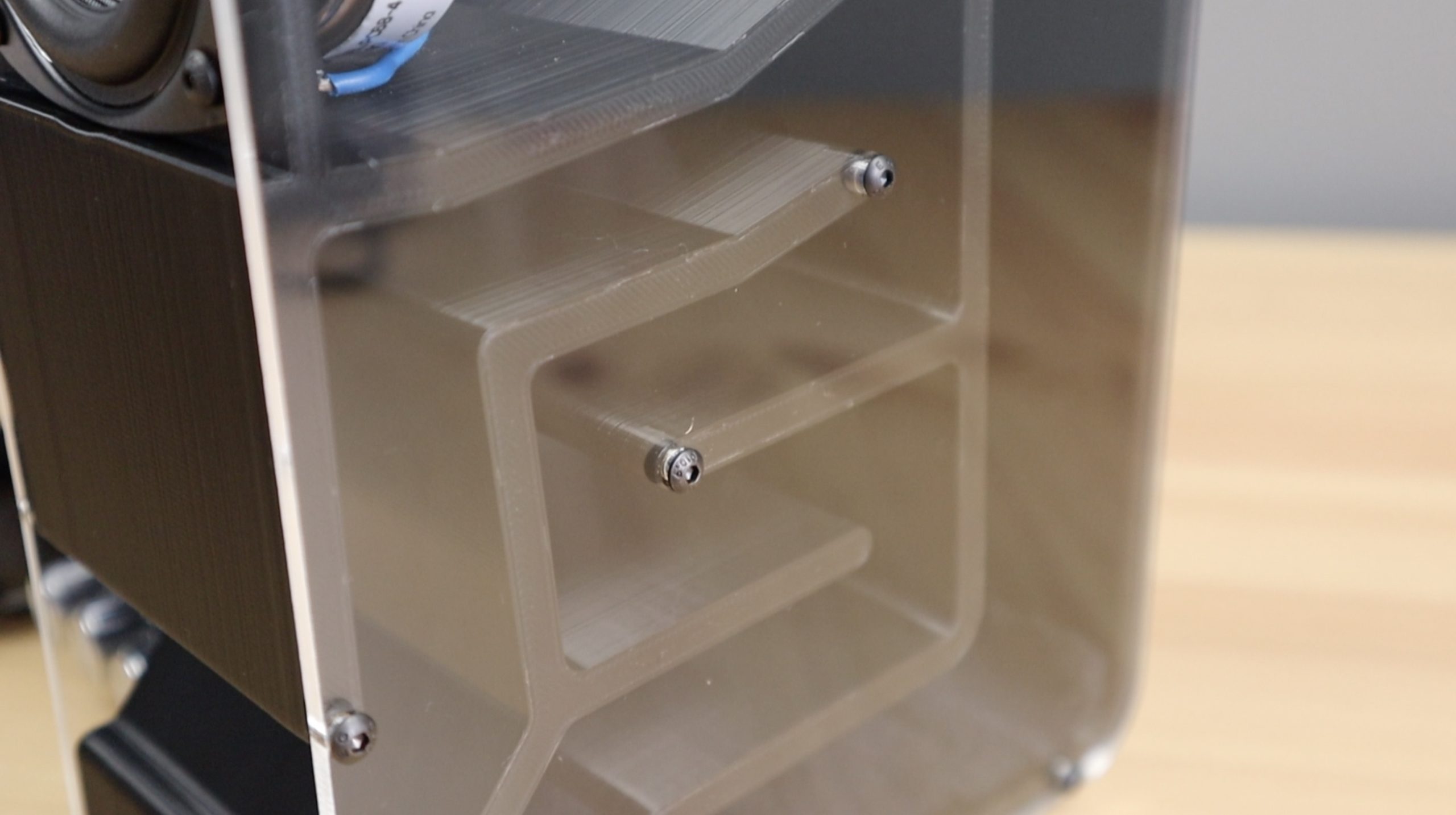
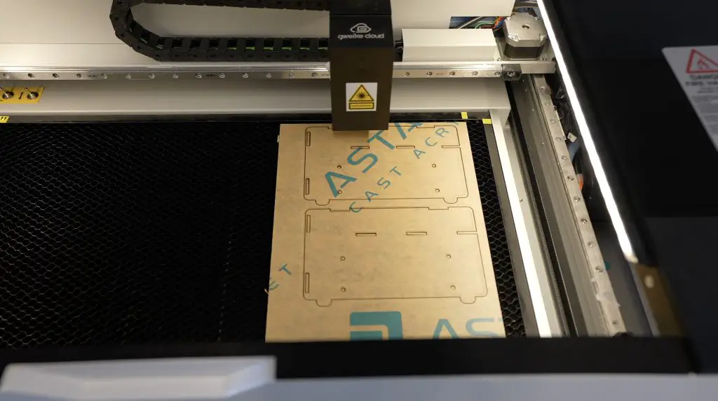
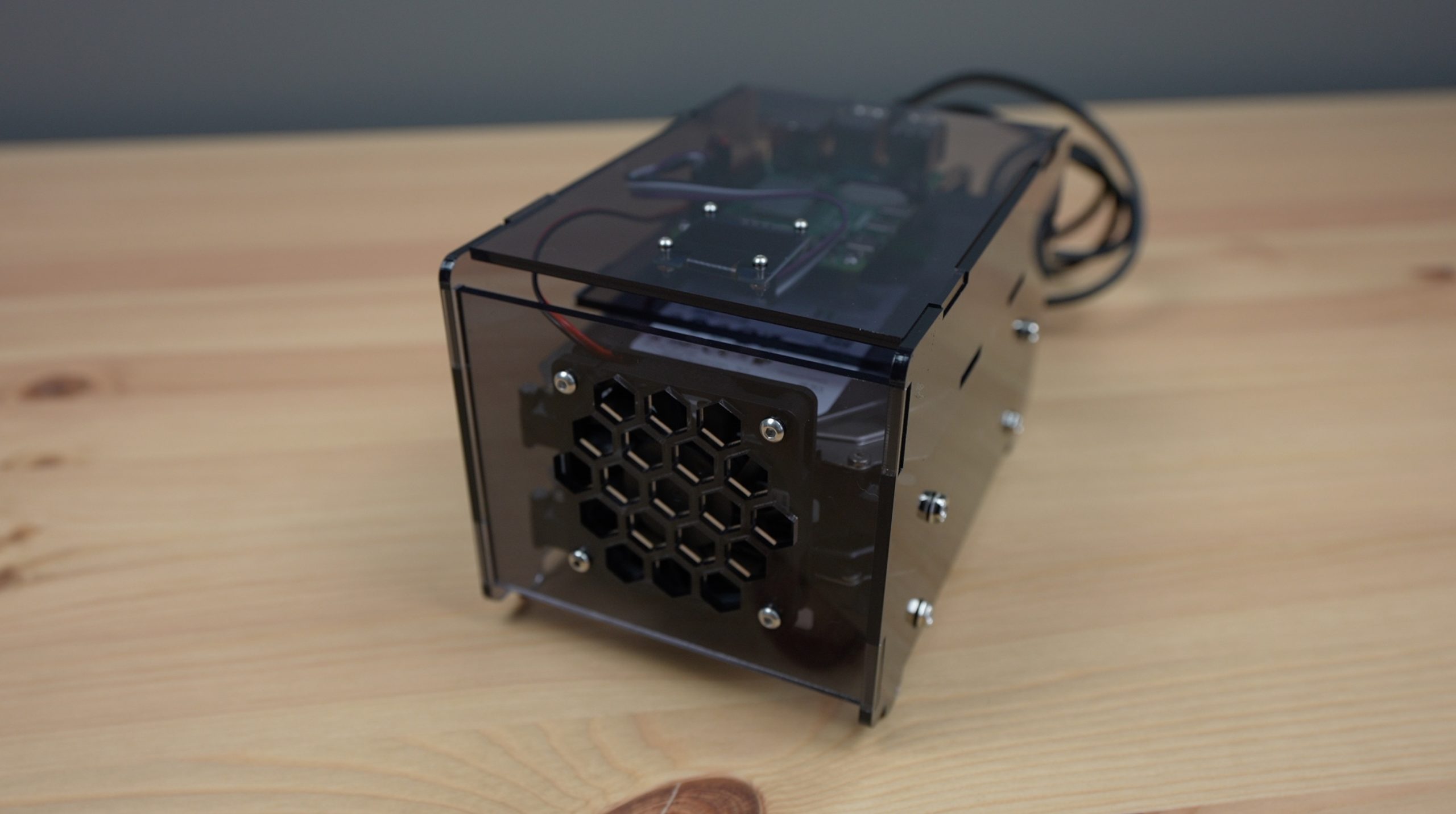
I then cut them out on my laser cutter. I cut them from 3mm tinted acrylic for a blacked-out look that the OLED display would still be visible through. You could also use clear or coloured translucent acrylic sheets if you’d like a different colour.
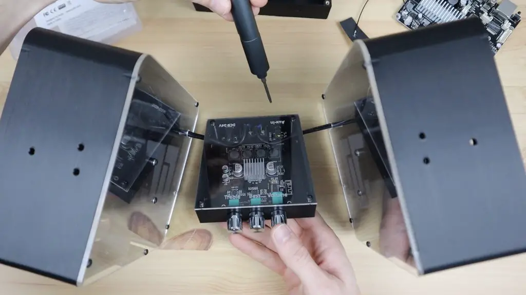
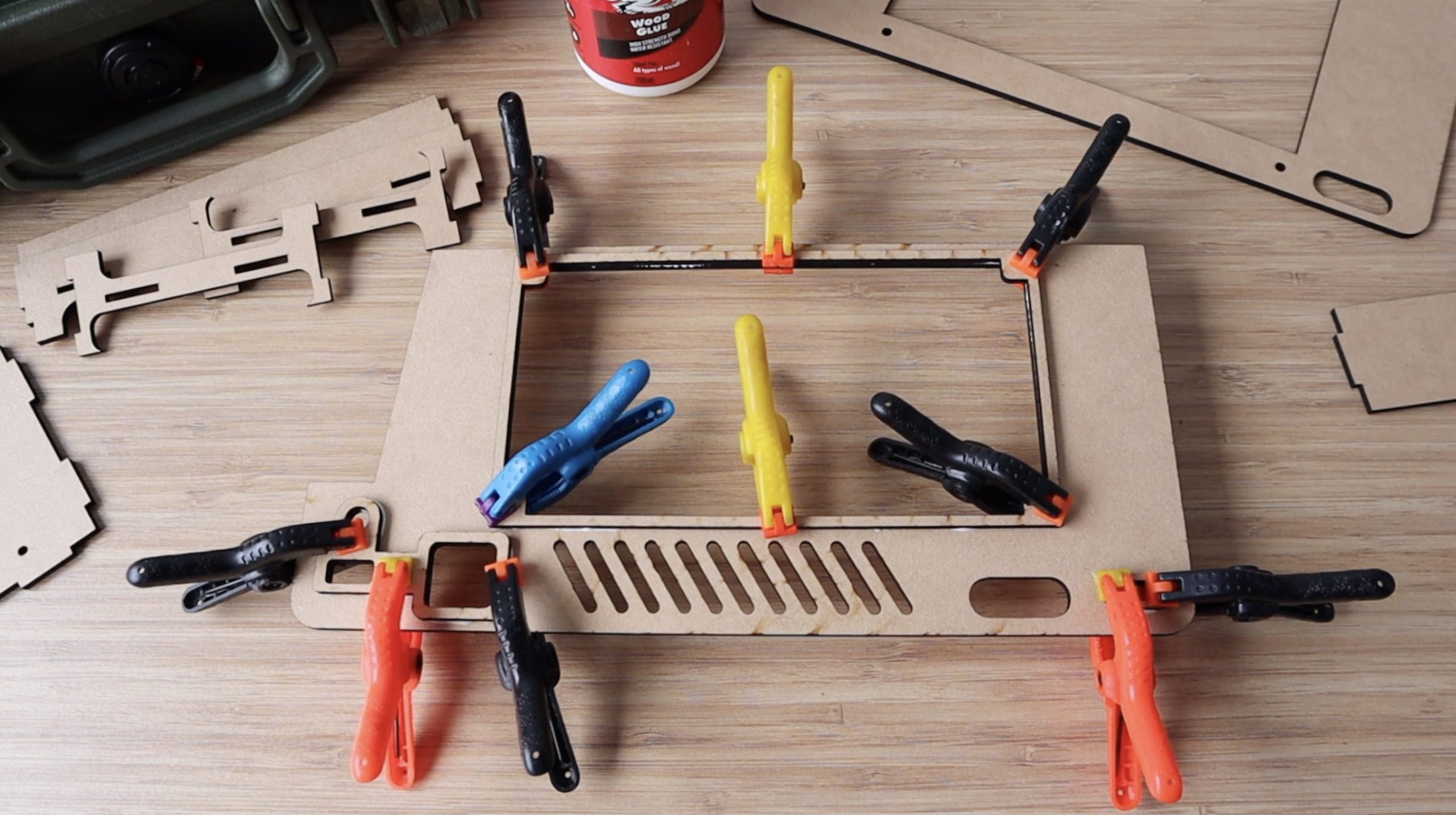
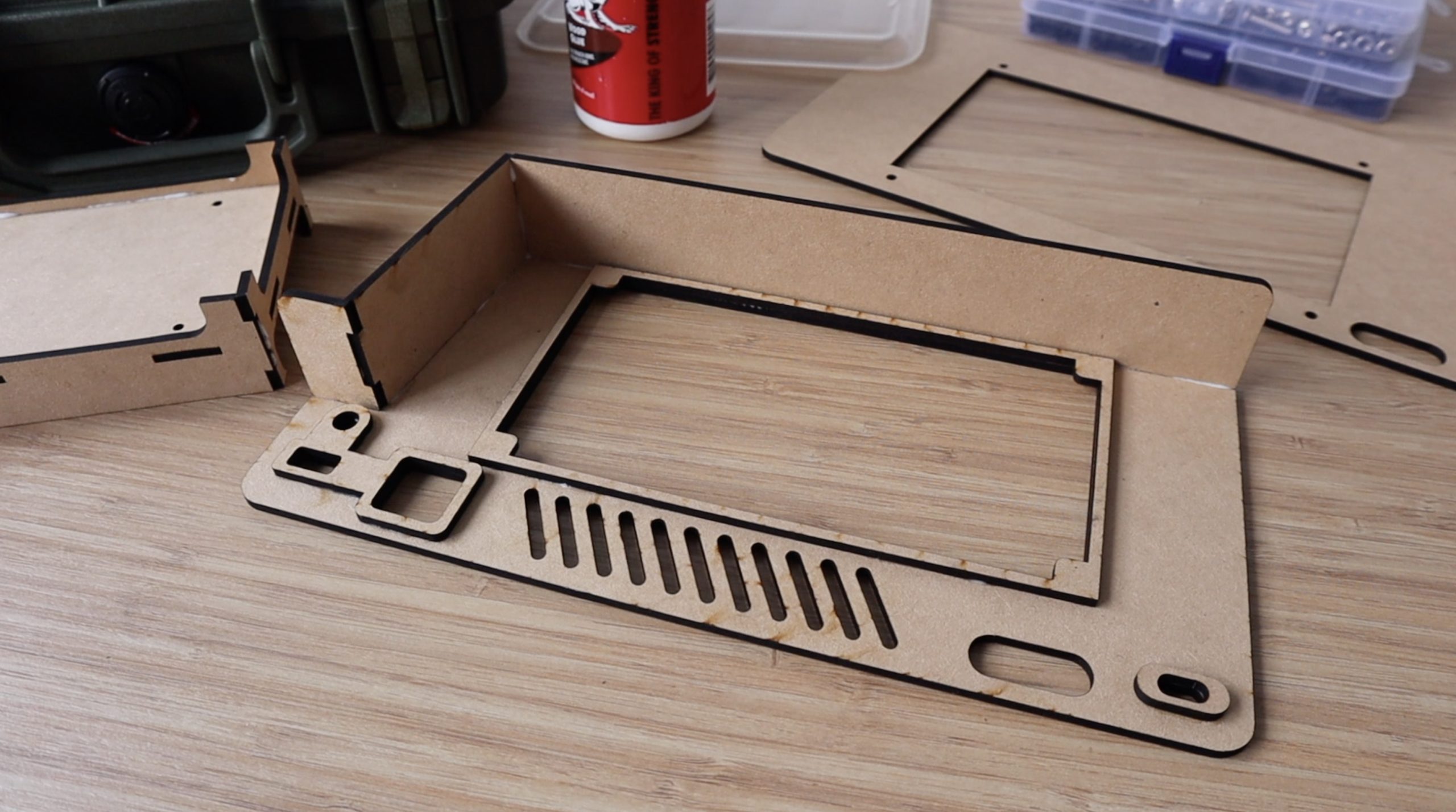
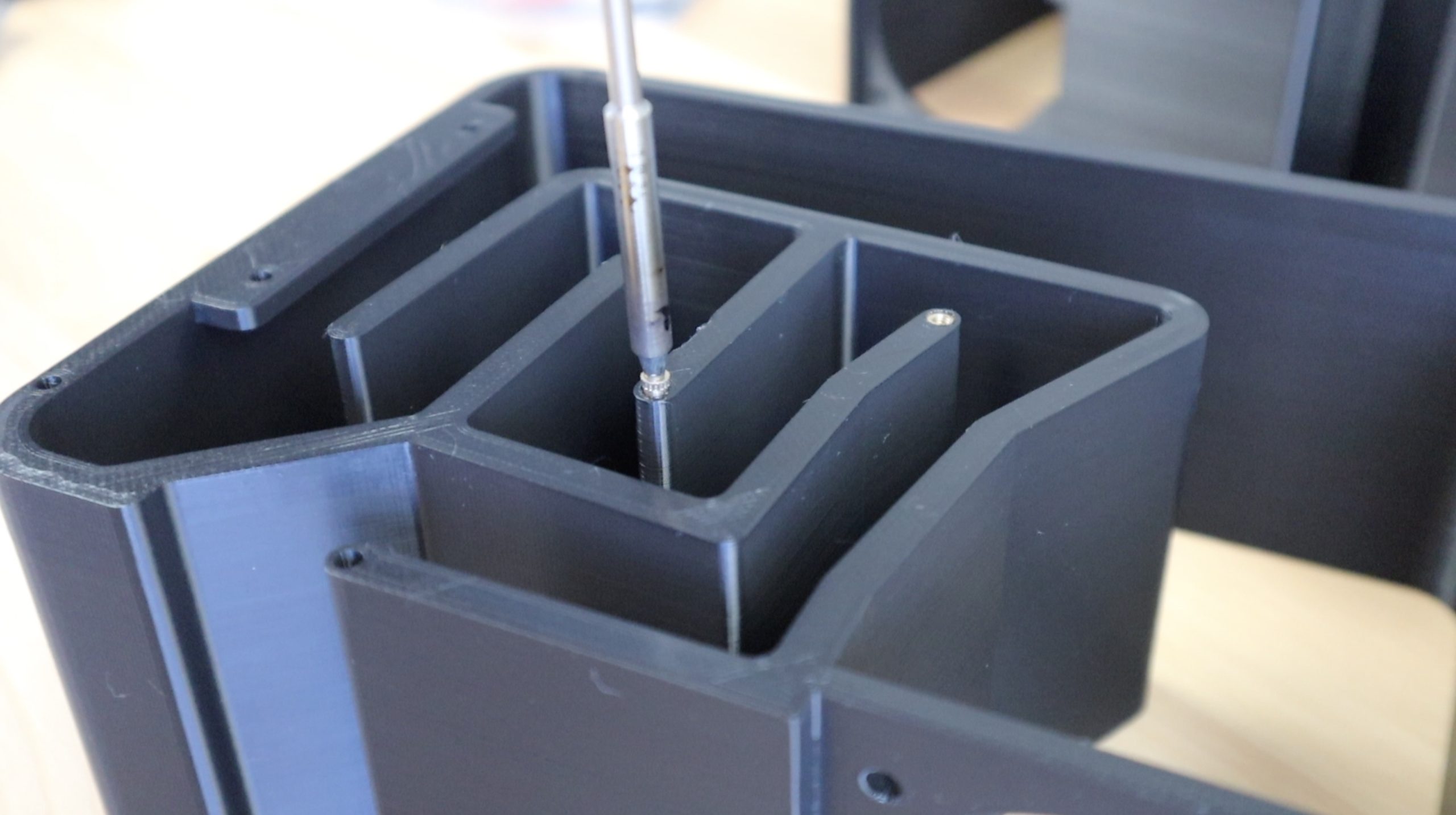
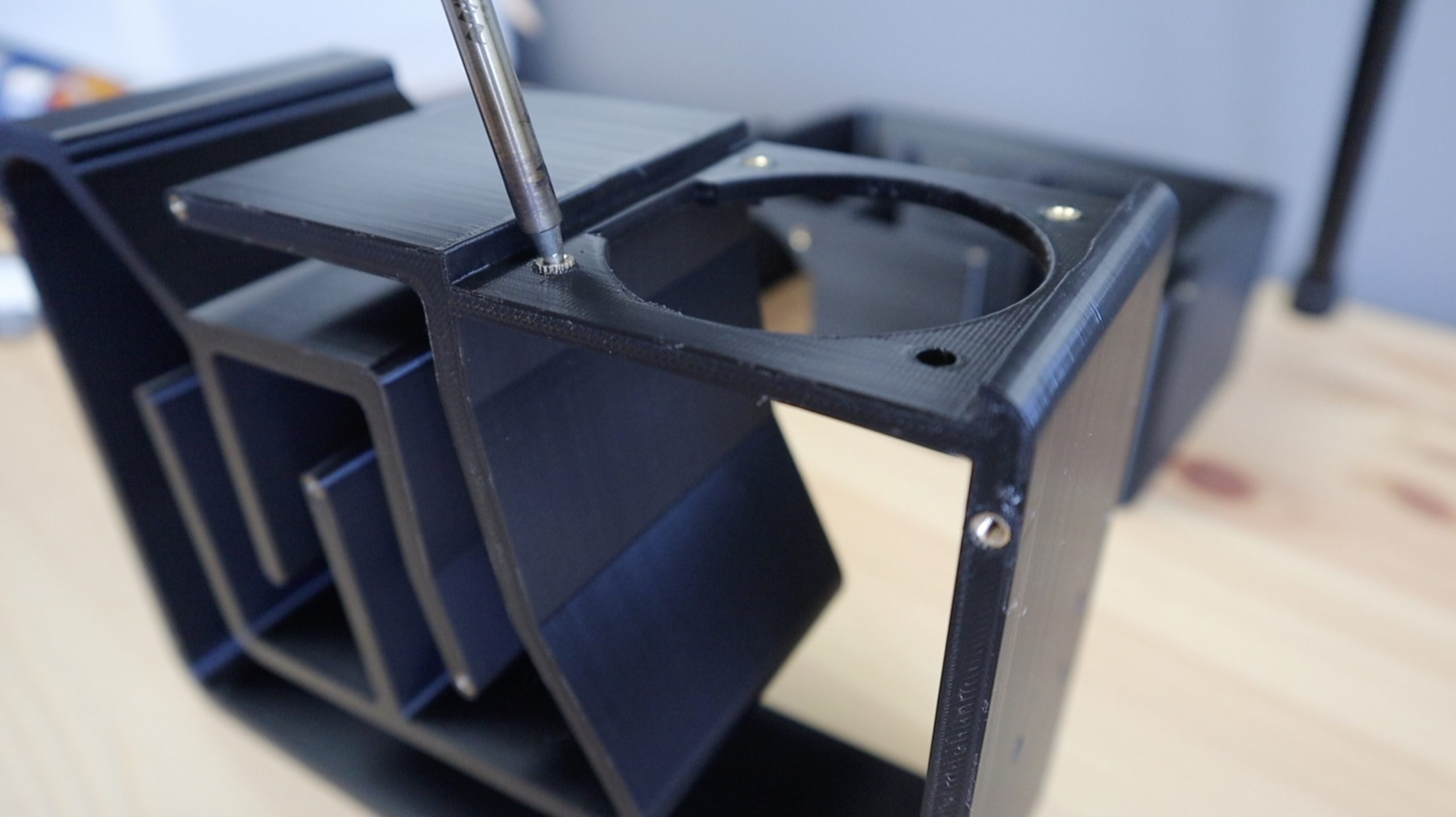
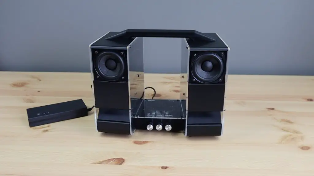
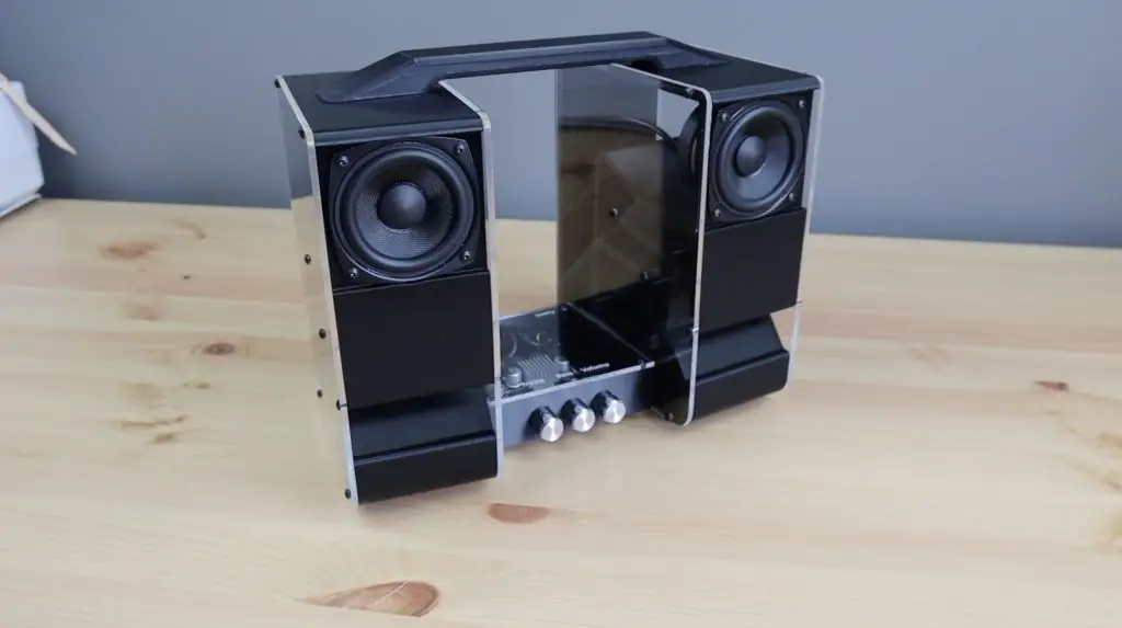
Assembling The NAS Hardware
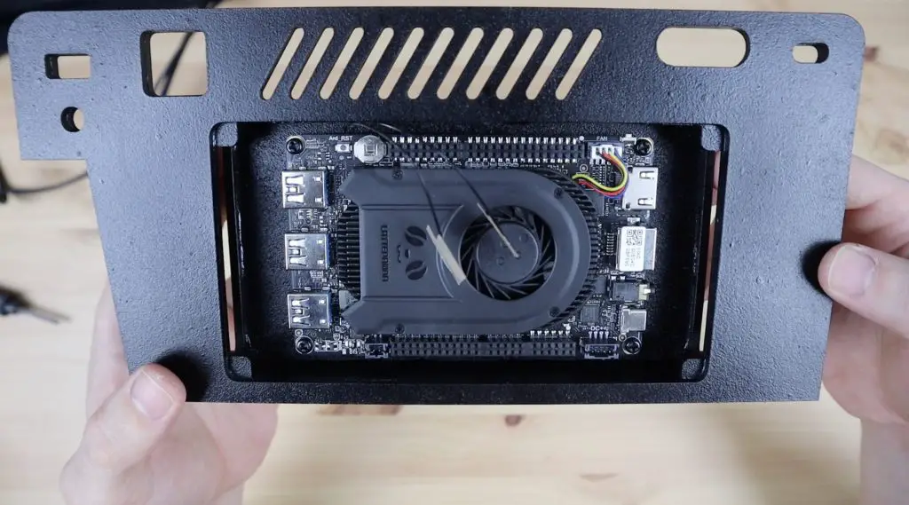
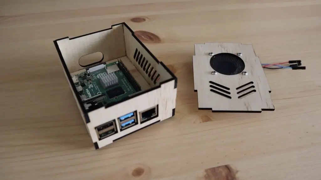
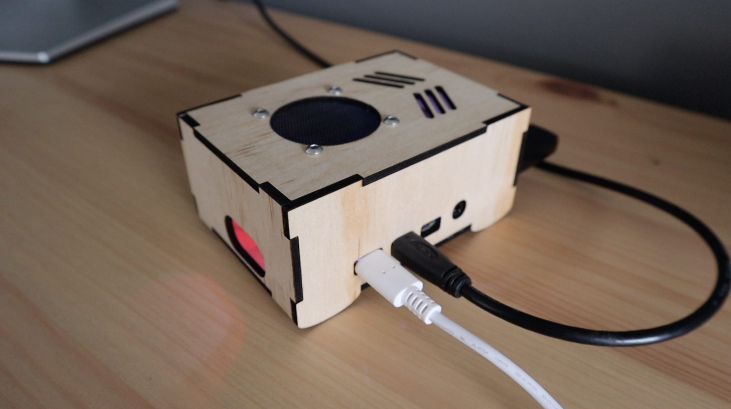
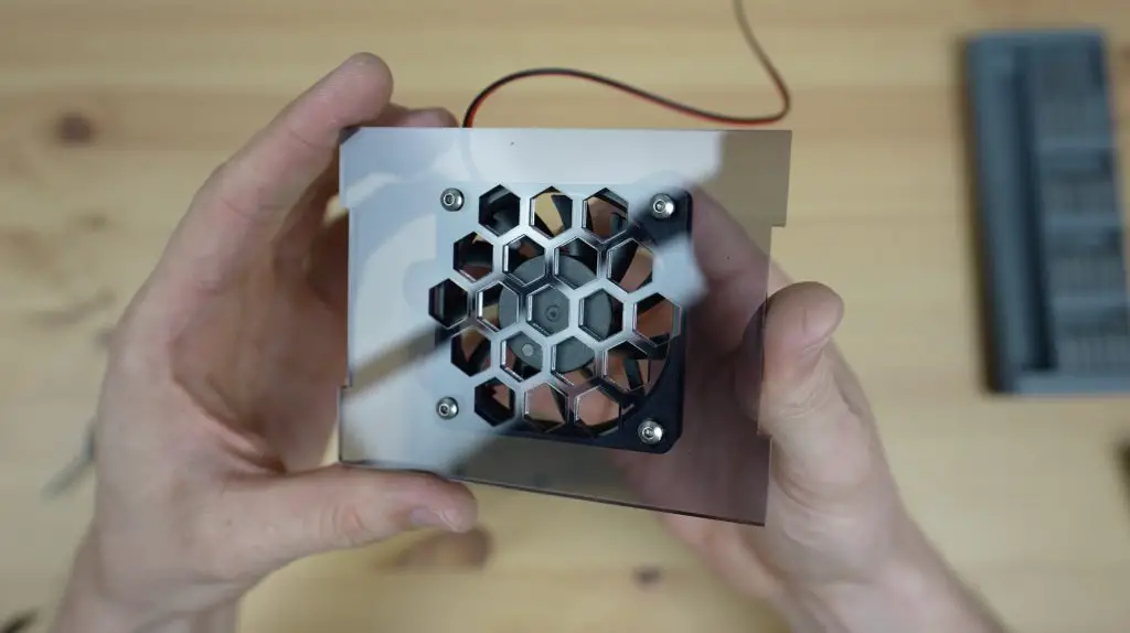
To assemble the NAS, the fan gets mounted onto the front panel with some M3 x 12mm button head screws and M3 nuts.
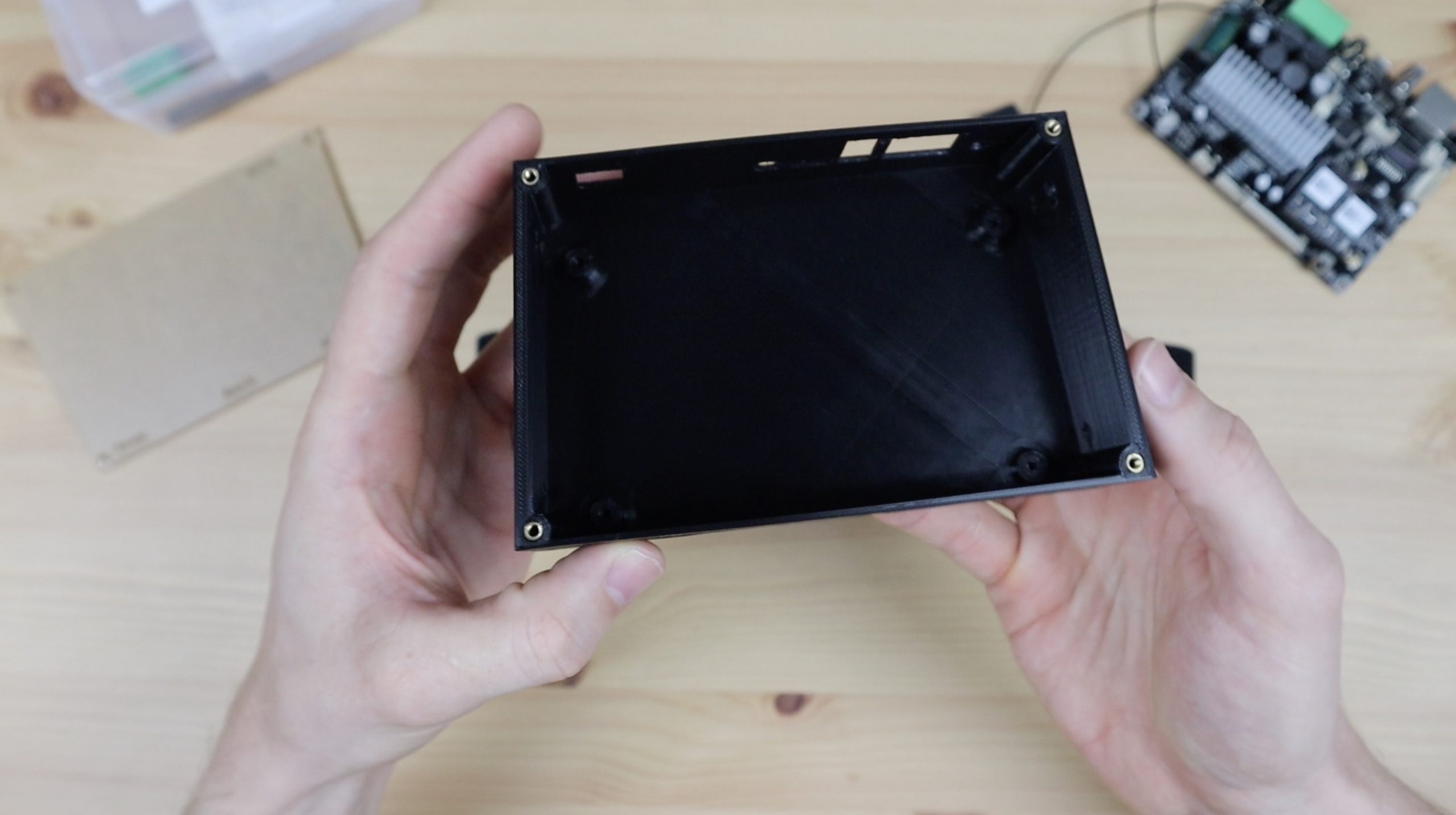
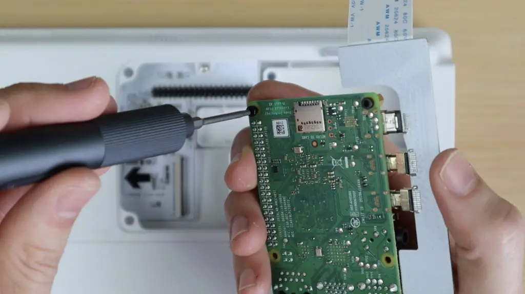
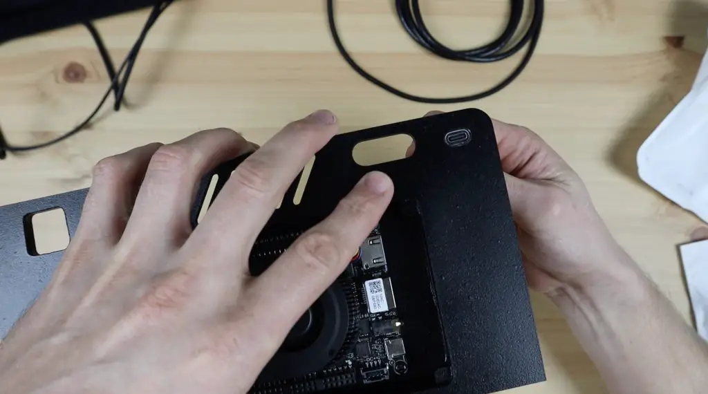
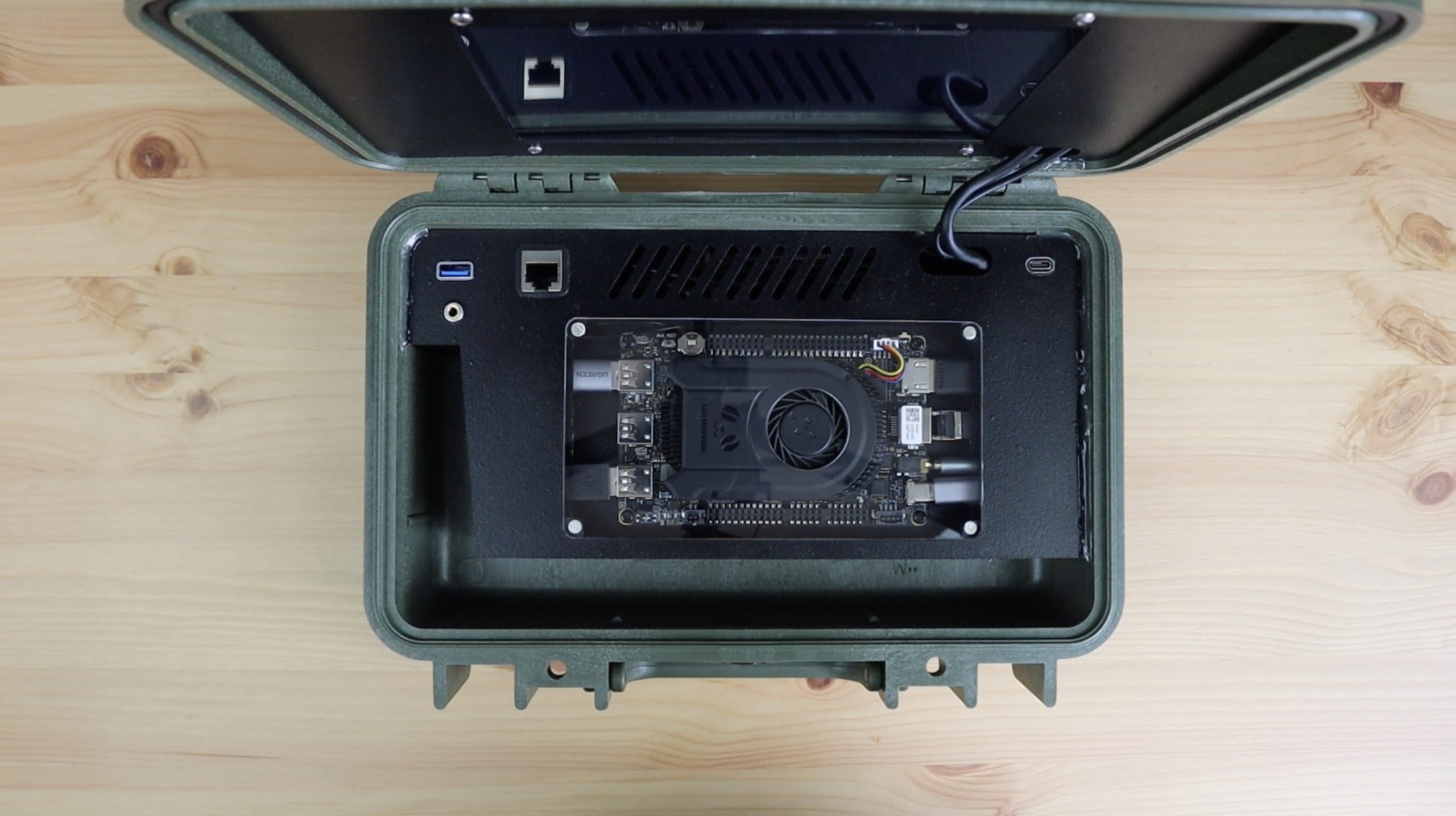
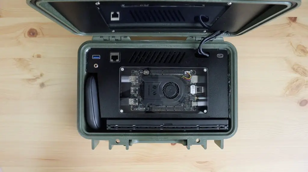
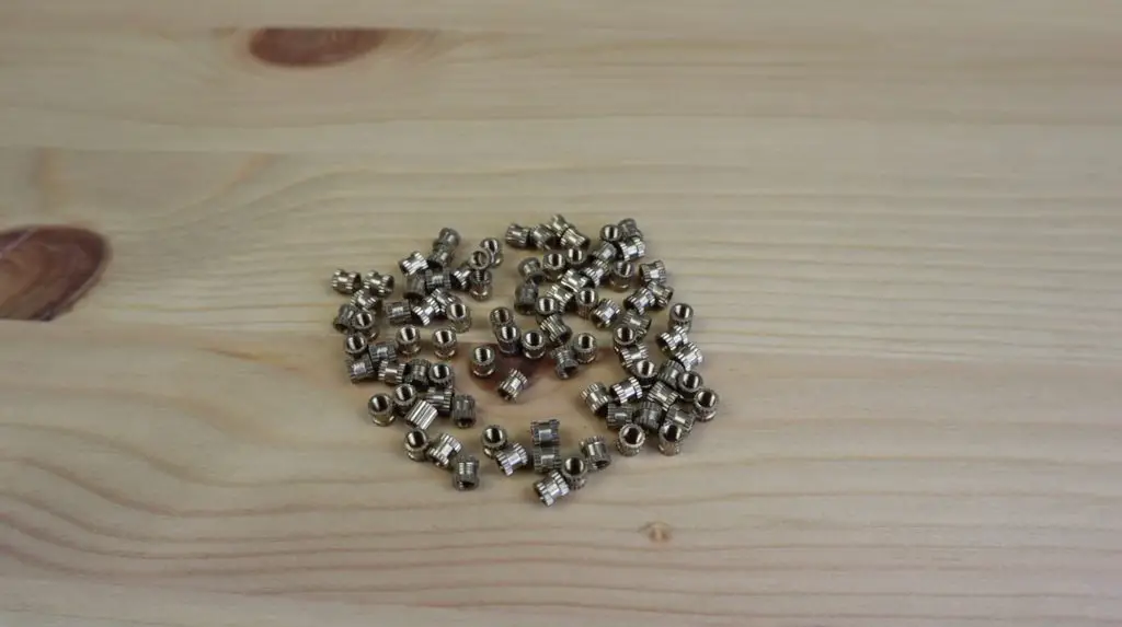
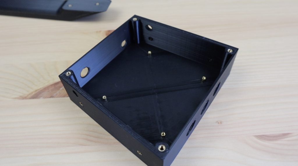
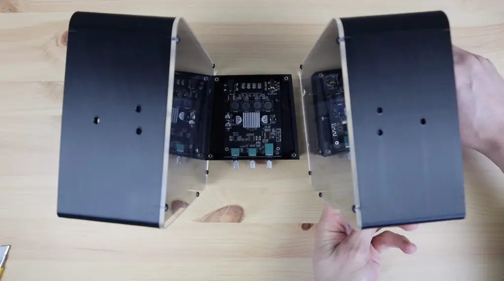
We can then mount the Raspberry Pi onto the middle panel with some M2.5 x 6mm brass standoffs, M2.5 x 6mm button head screws and M2.5 nuts.
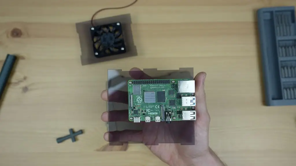
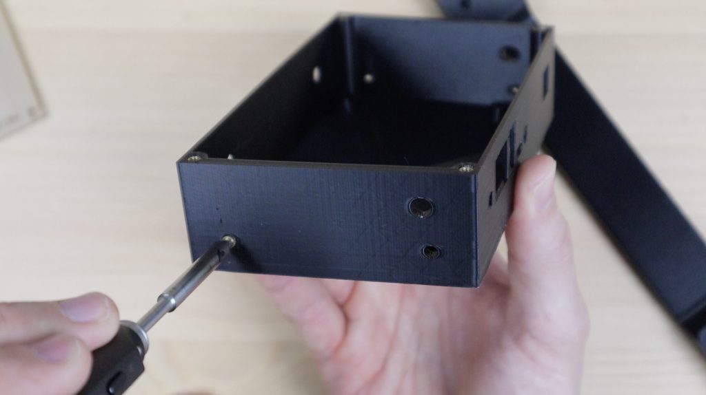
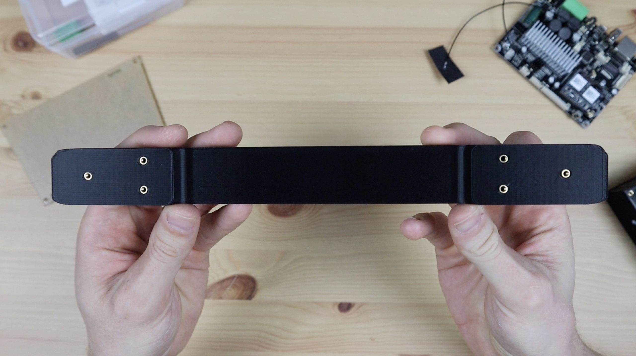
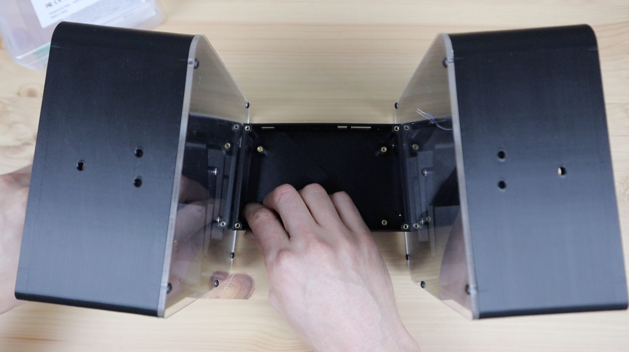
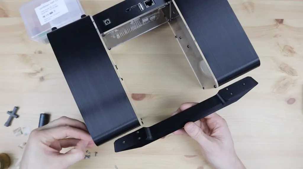
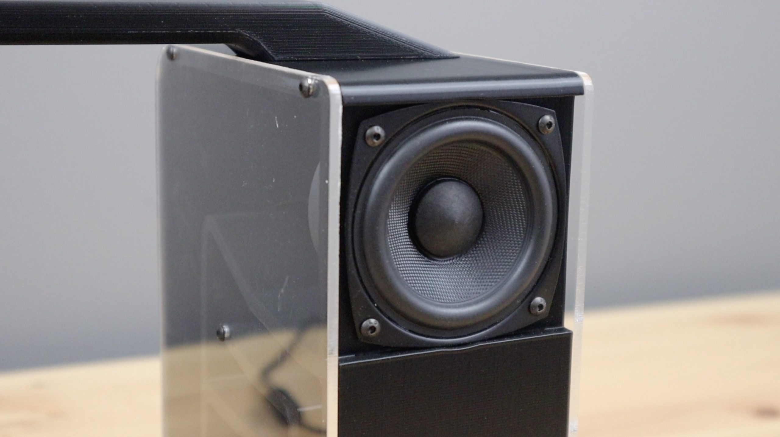
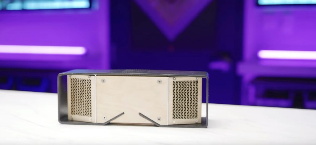
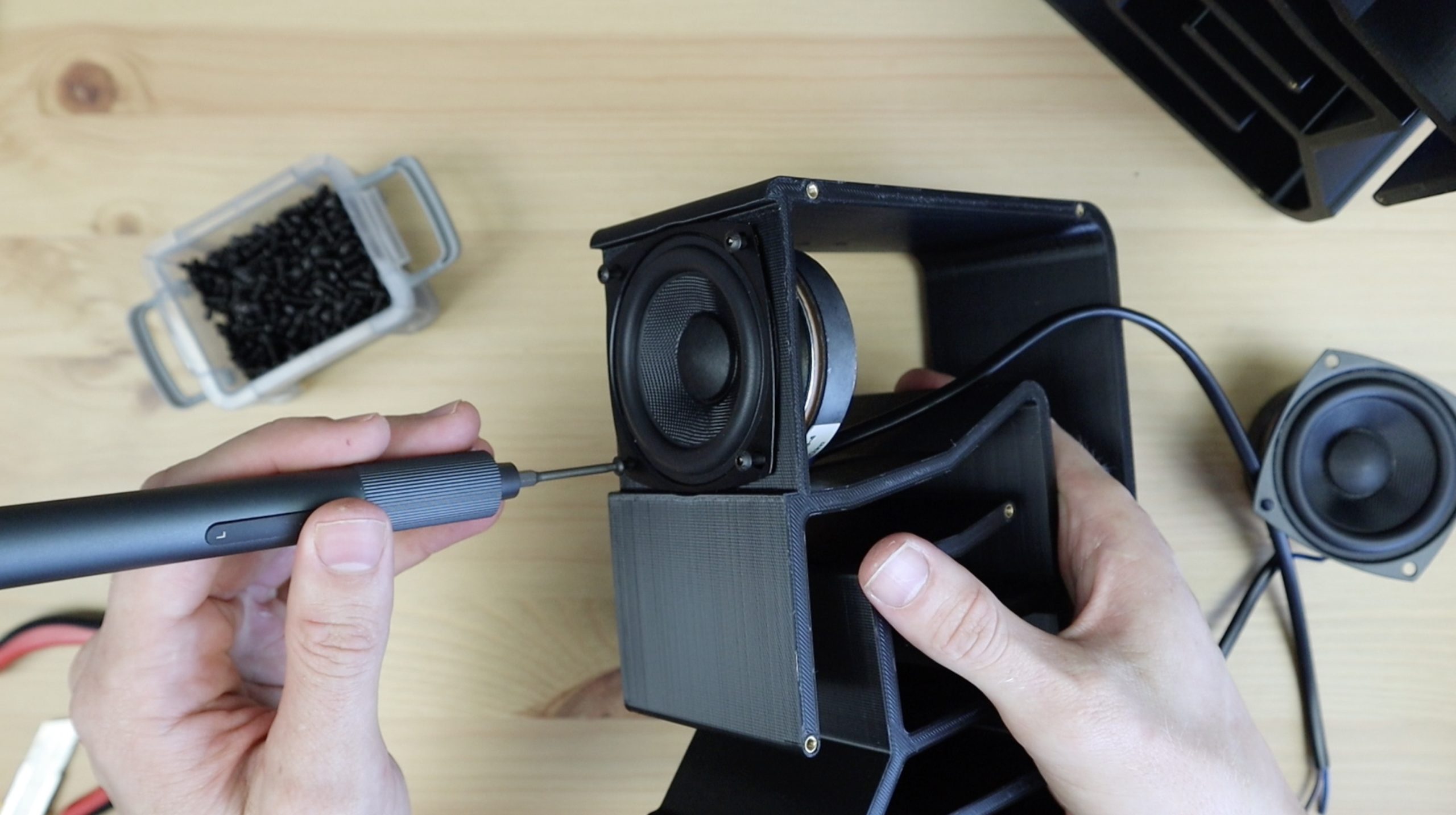
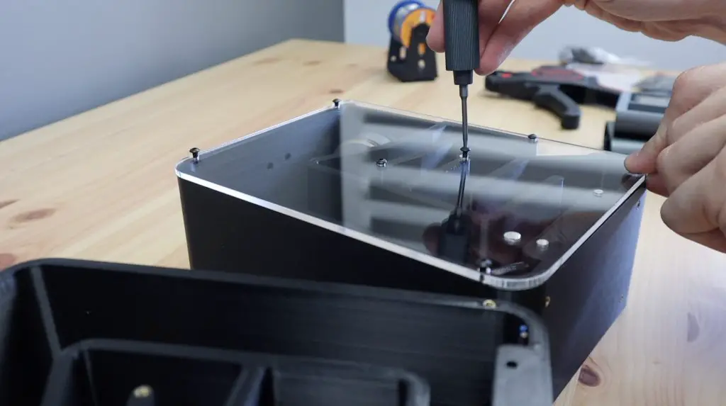
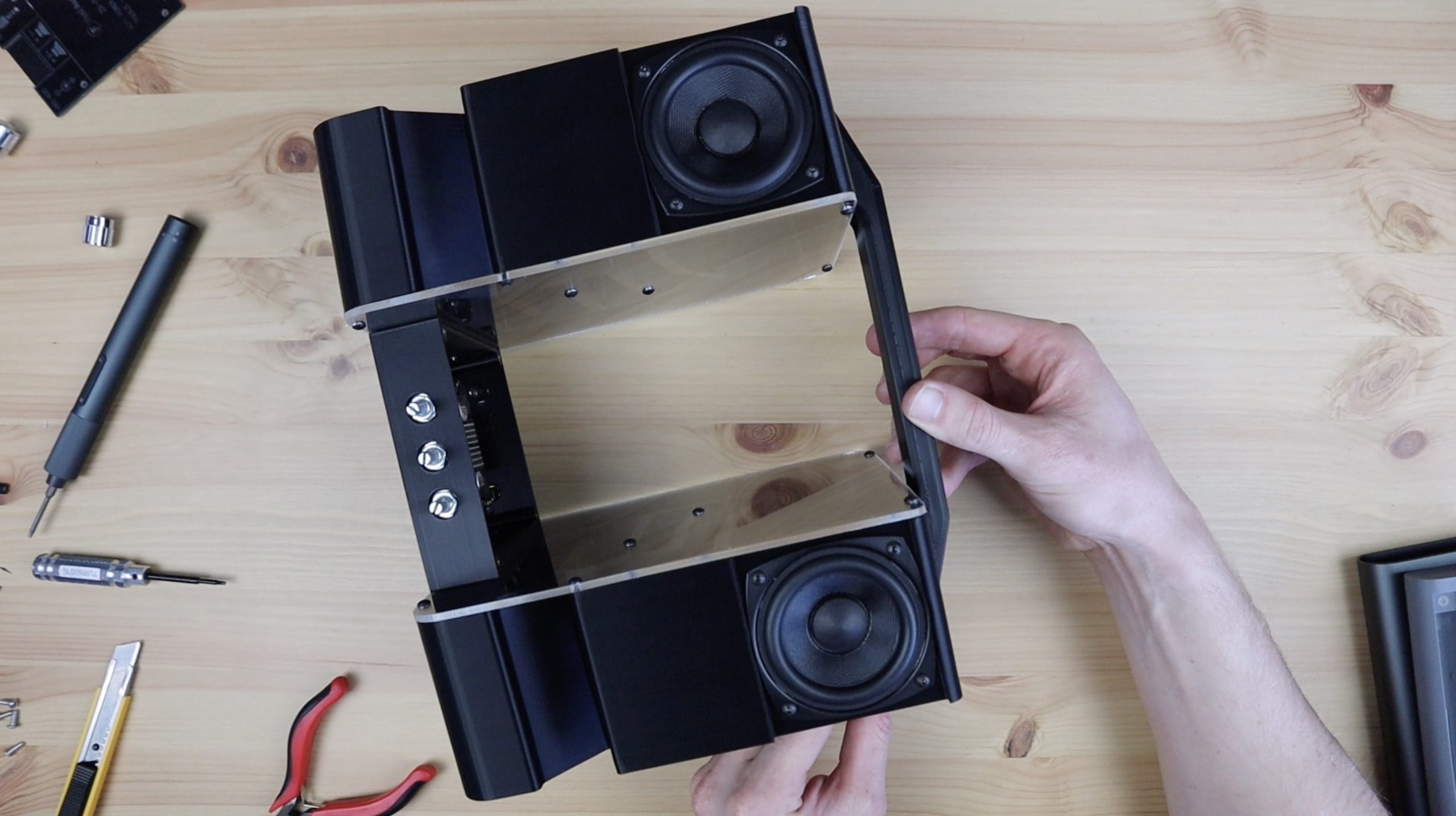
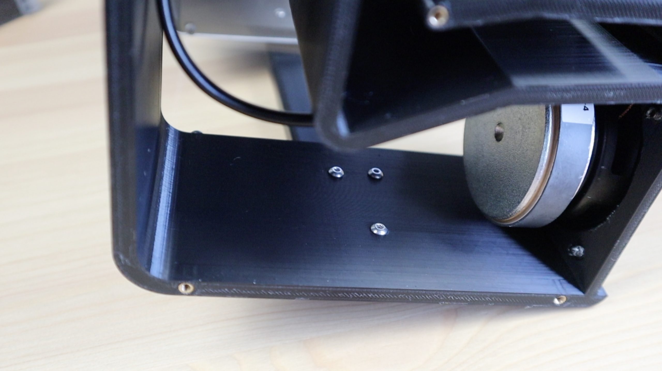
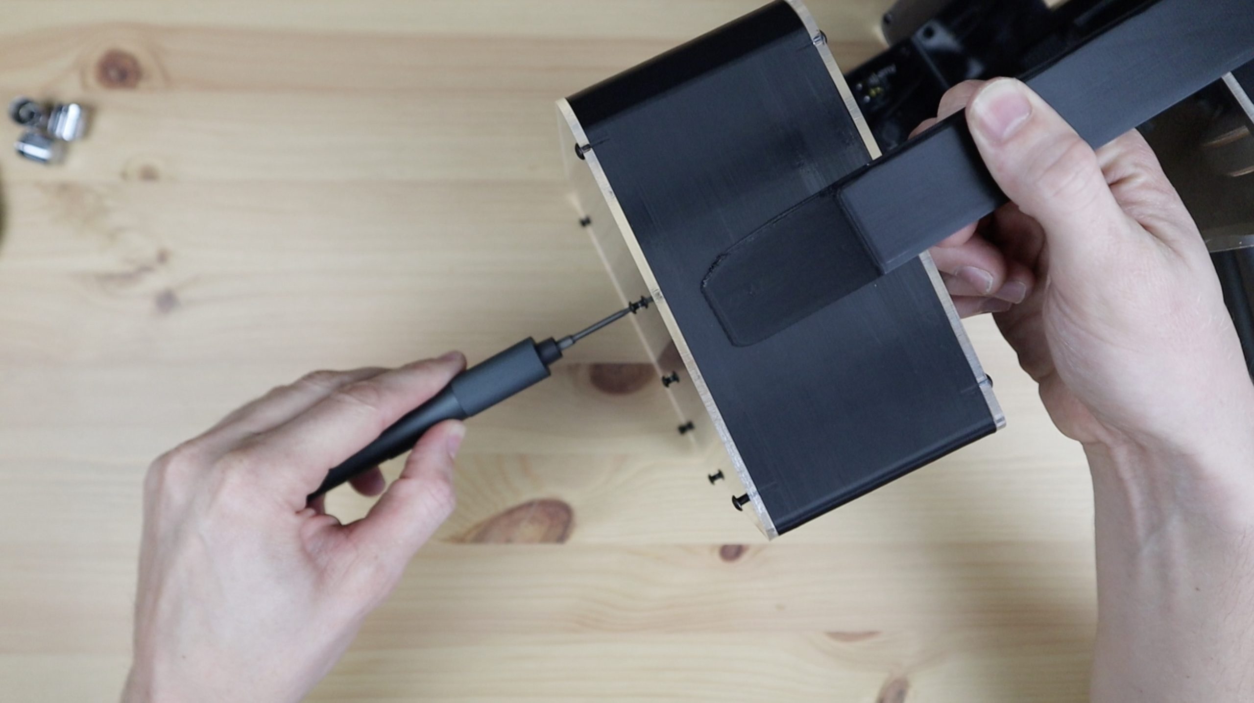
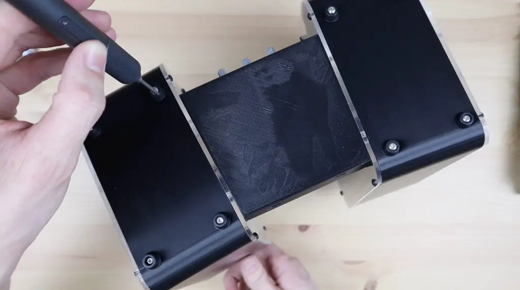
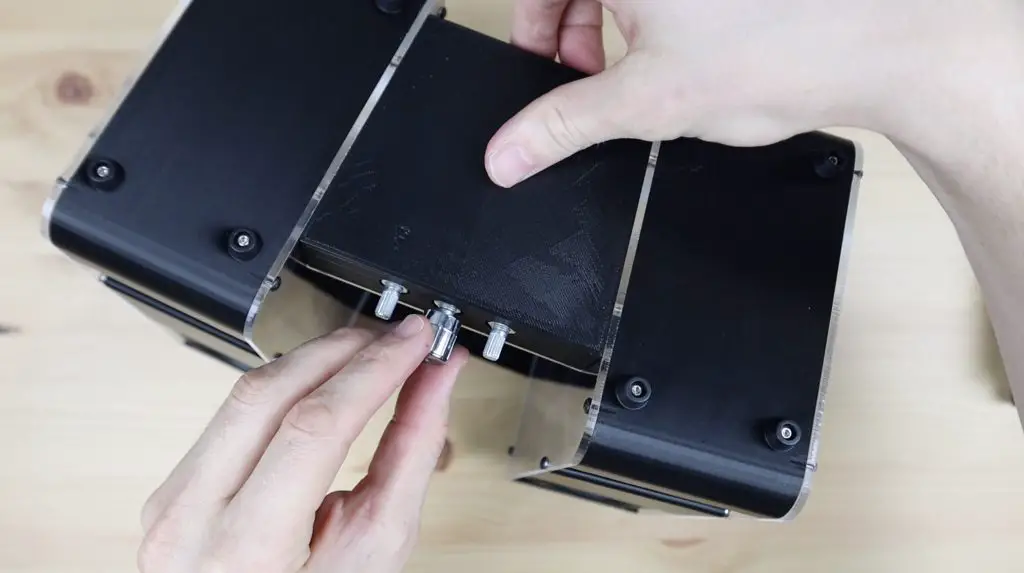
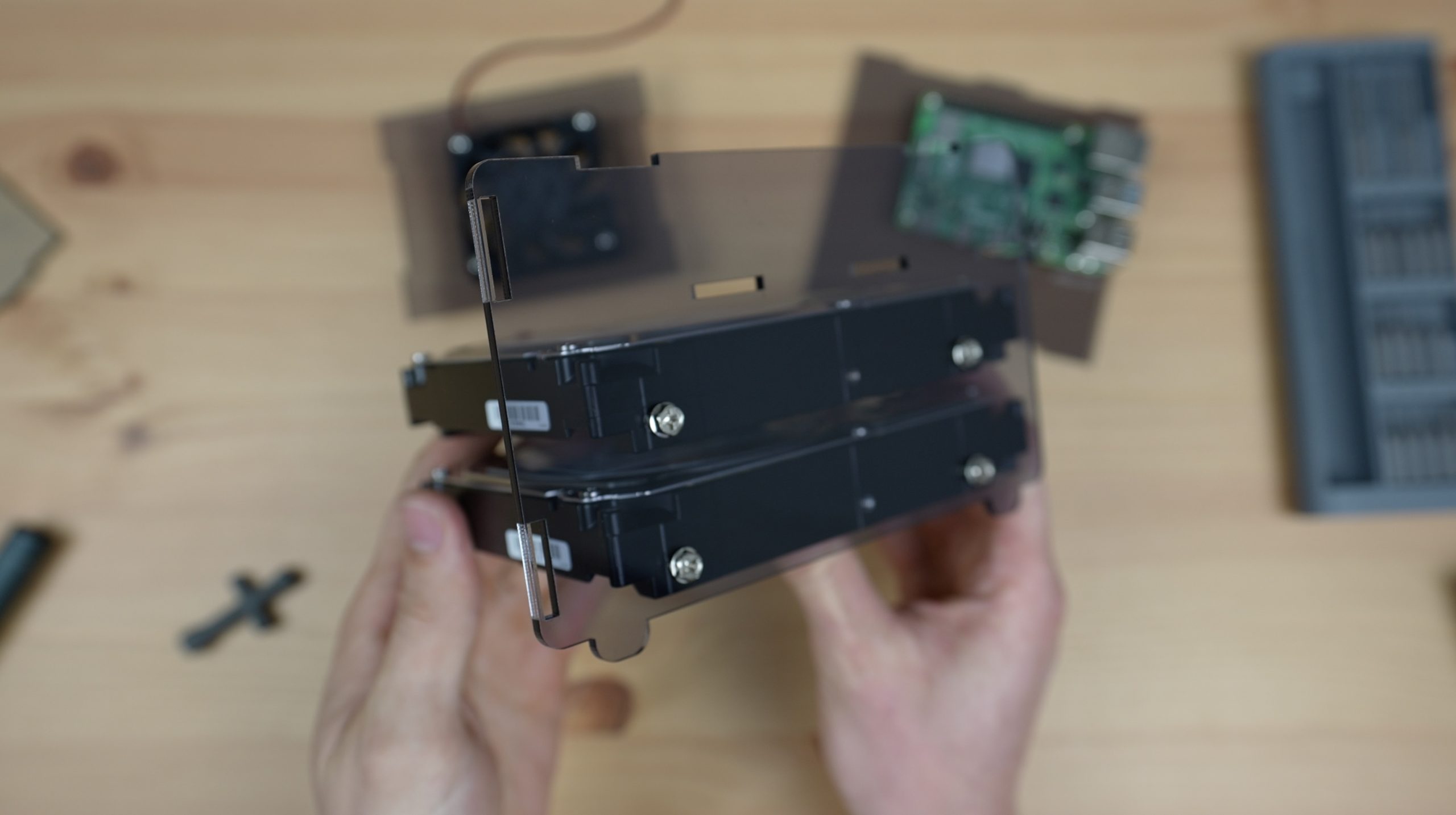
The drives hold the side panels in place using four #6-32 UNC Screws on each side (a total of 4 per drive), and these side panels then support the fan panel and Raspberry Pi panel. Make sure that you position the tabs on the fan and Pi panel within the slots in the side panels before securing the second side panel to the drives.
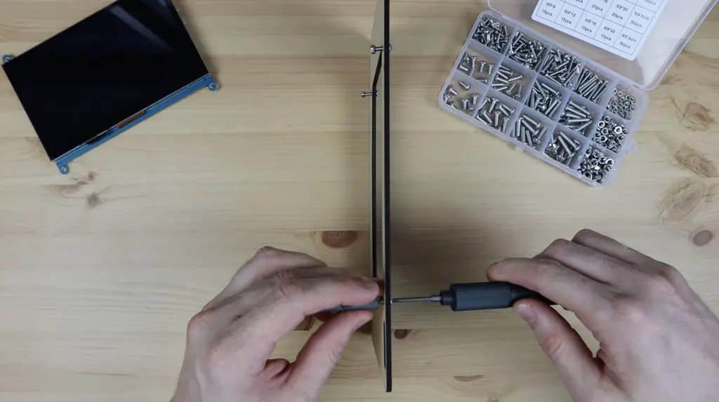
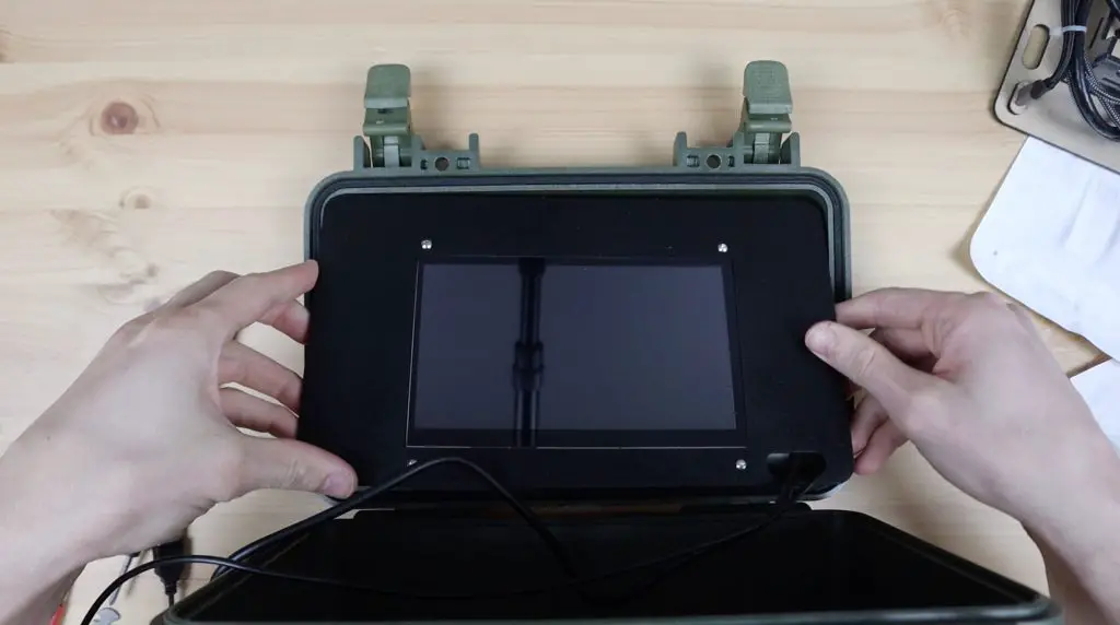
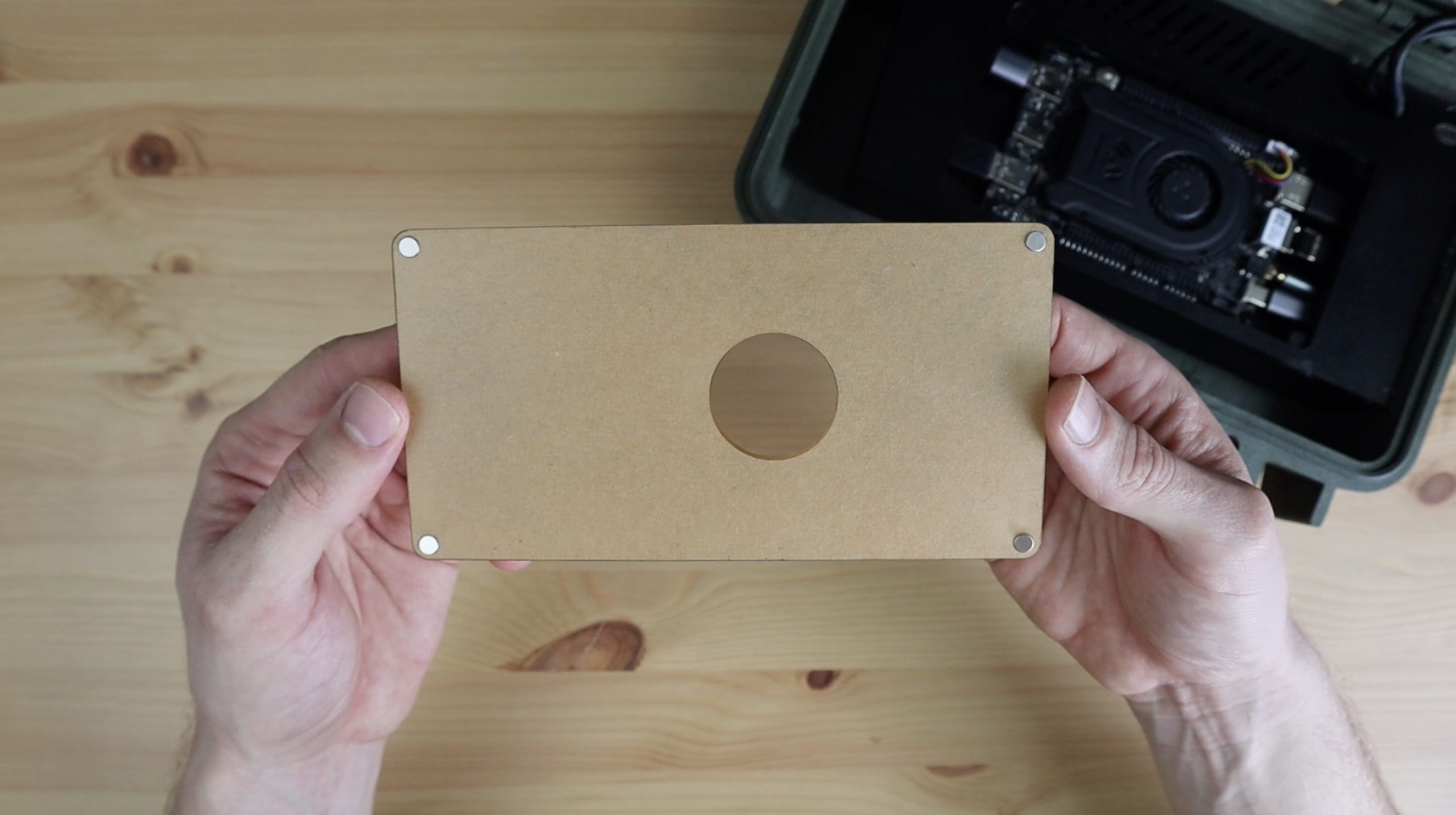
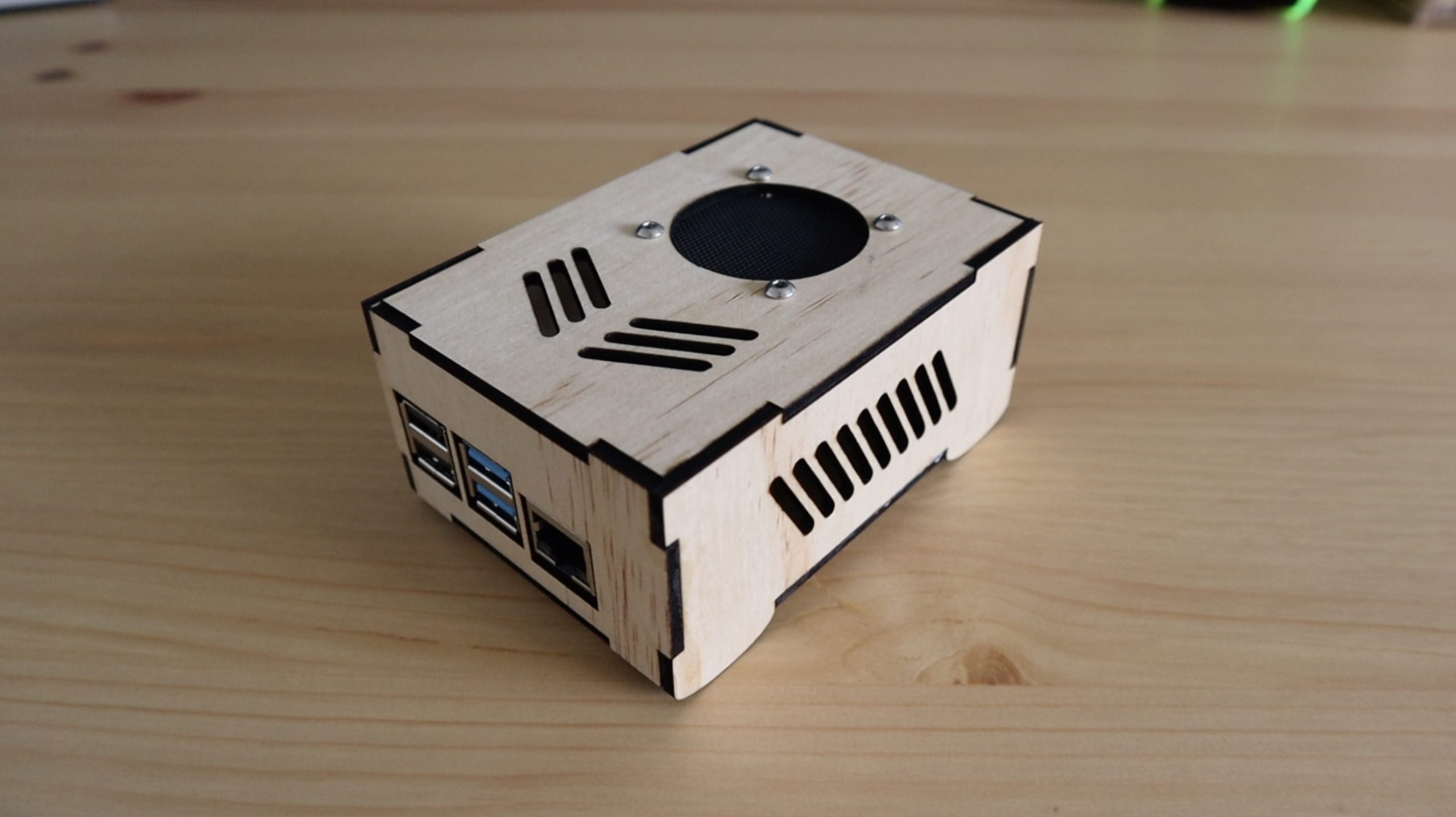
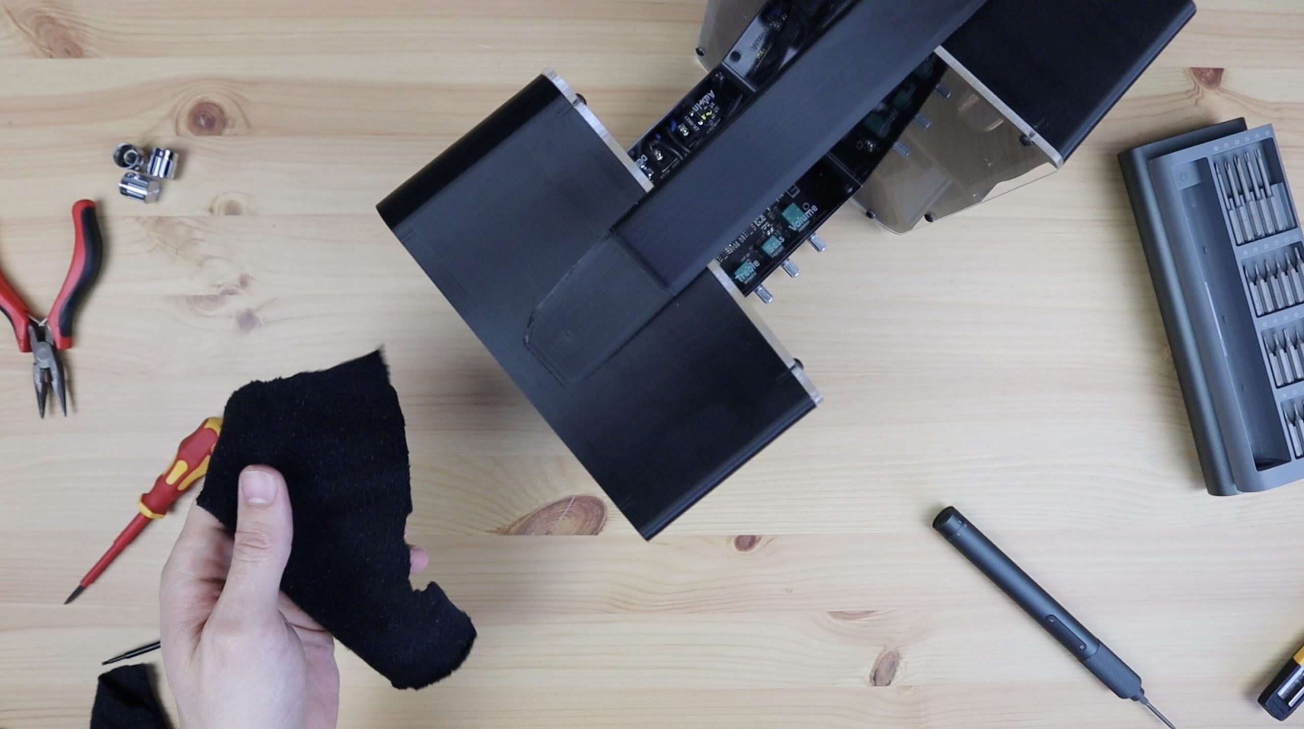
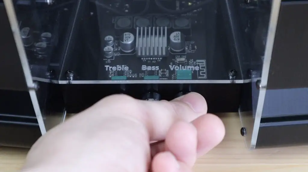
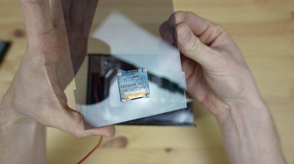
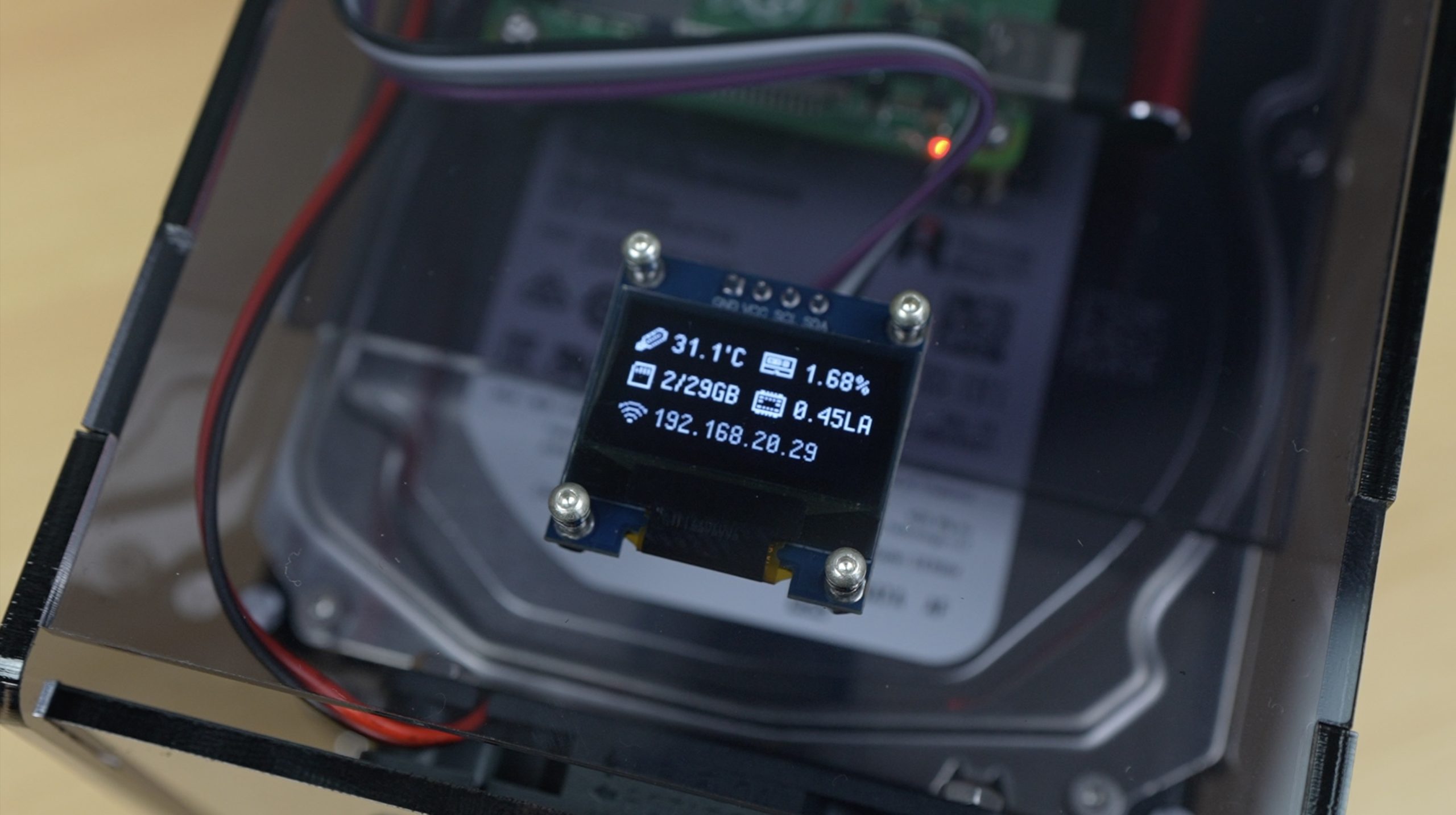
Lastly, we can mount the OLED display onto the top cover using four M2 x 10mm screws and M2 nuts. This top cover isn’t screwed down so that it is easily removable if we need to get to the Pi.
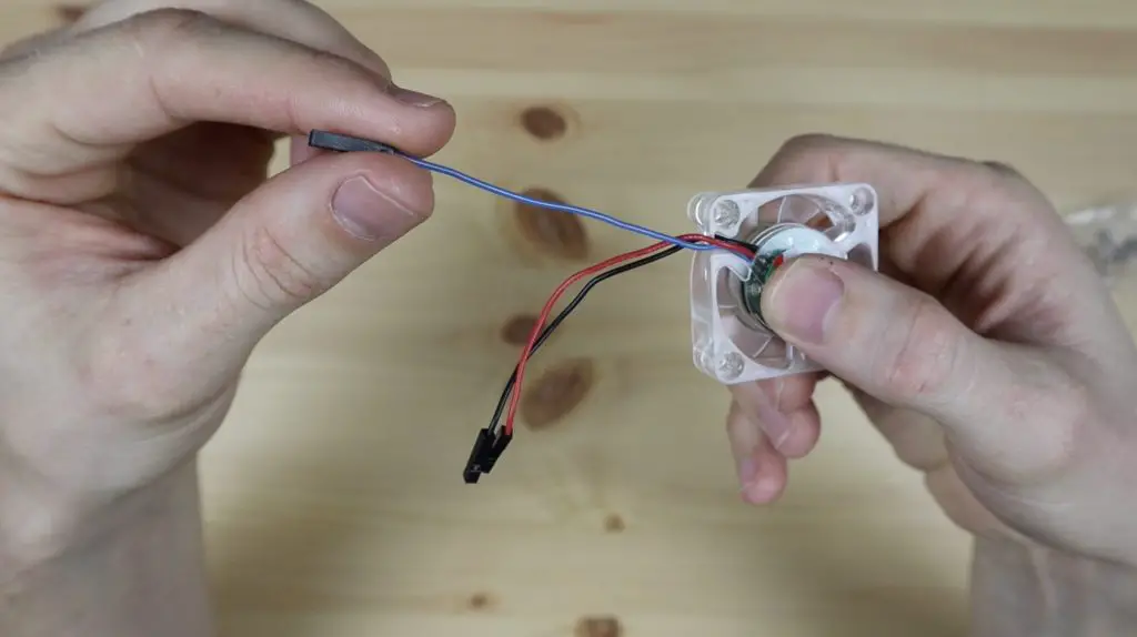
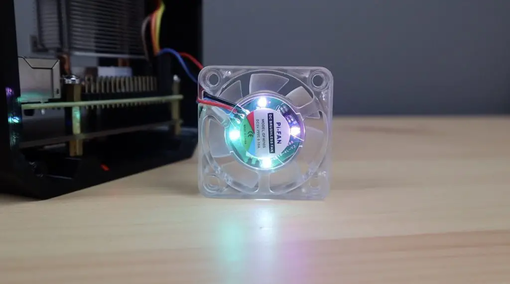
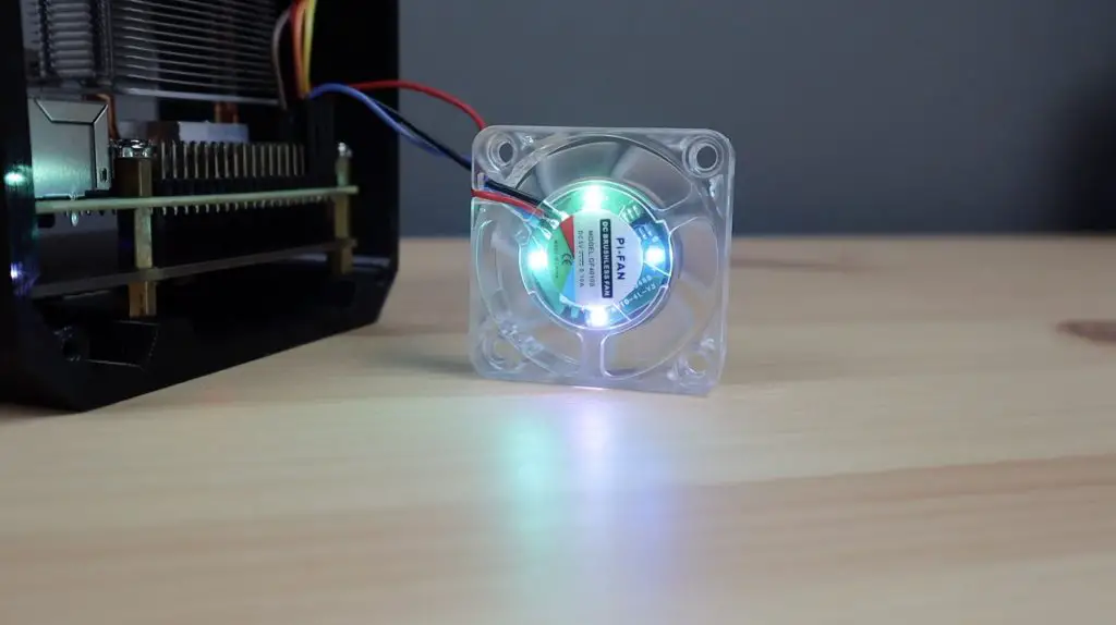
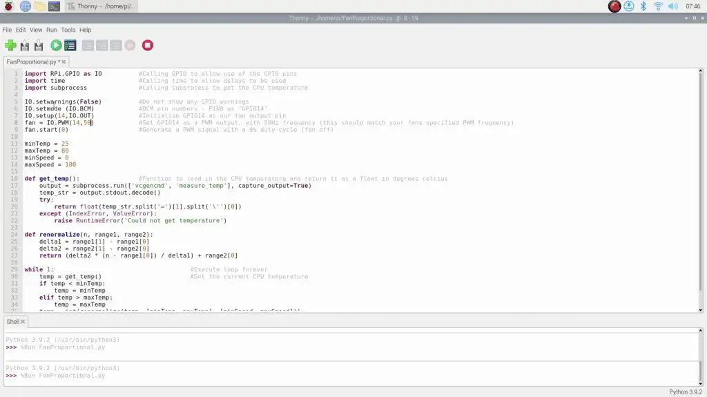
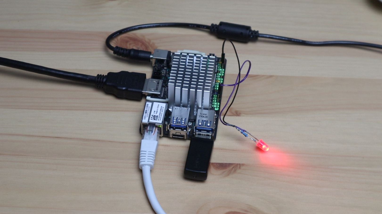
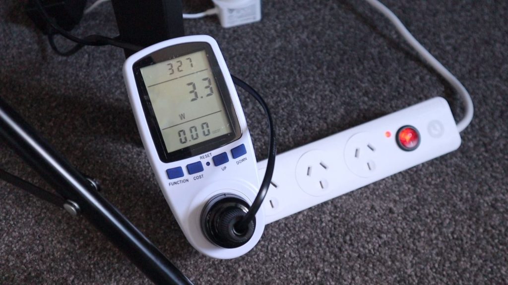
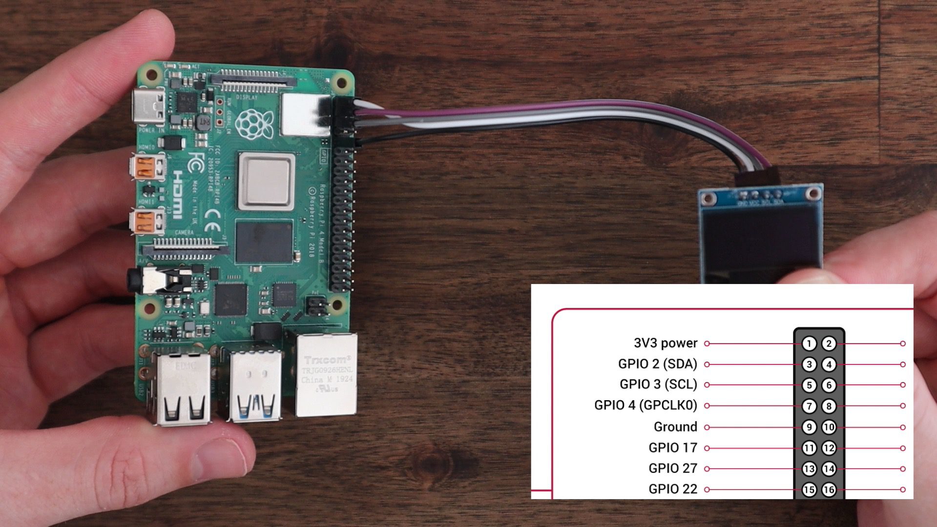
Before closing up the top cover, we need to connect the fan to 3.3V and GND (you can also use 5V, but I found that the fan ran quieter on 3.3V and still produced a fair amount of airflow), and connect the display to 3.3V and GND, and then Plug SCL into Pin 5 and SDA into Pin 3. If you need more help with this, take a look at my guide on connecting an OLED stats display to a Raspberry Pi.
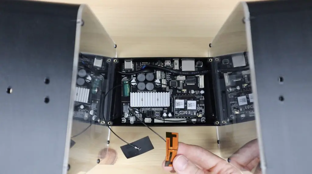
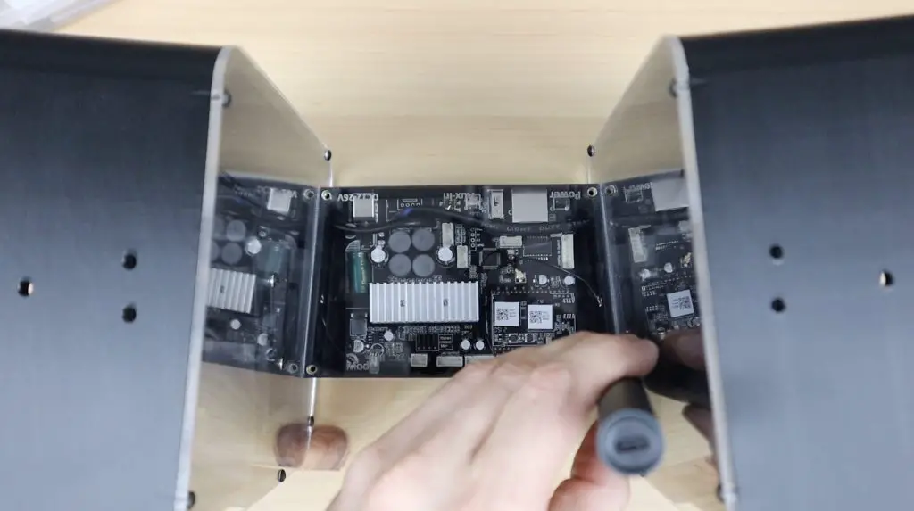
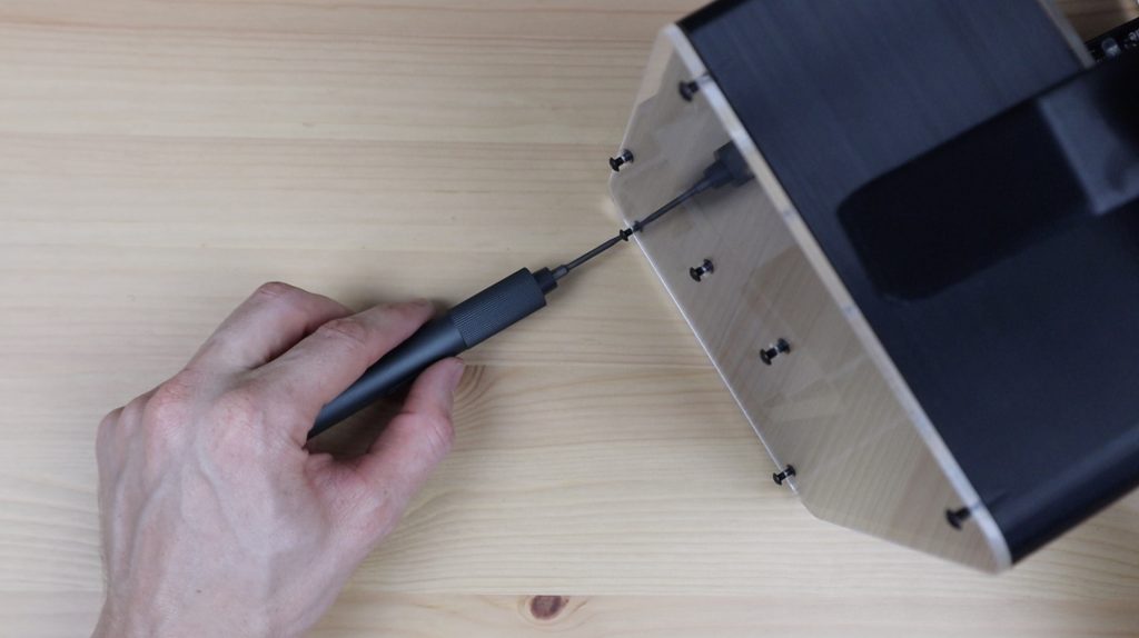
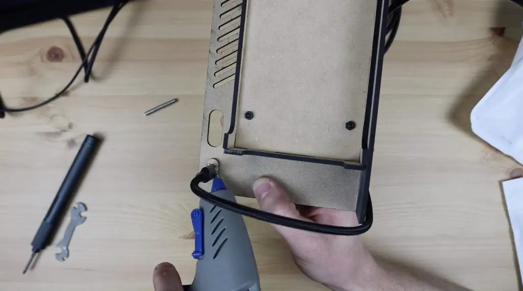
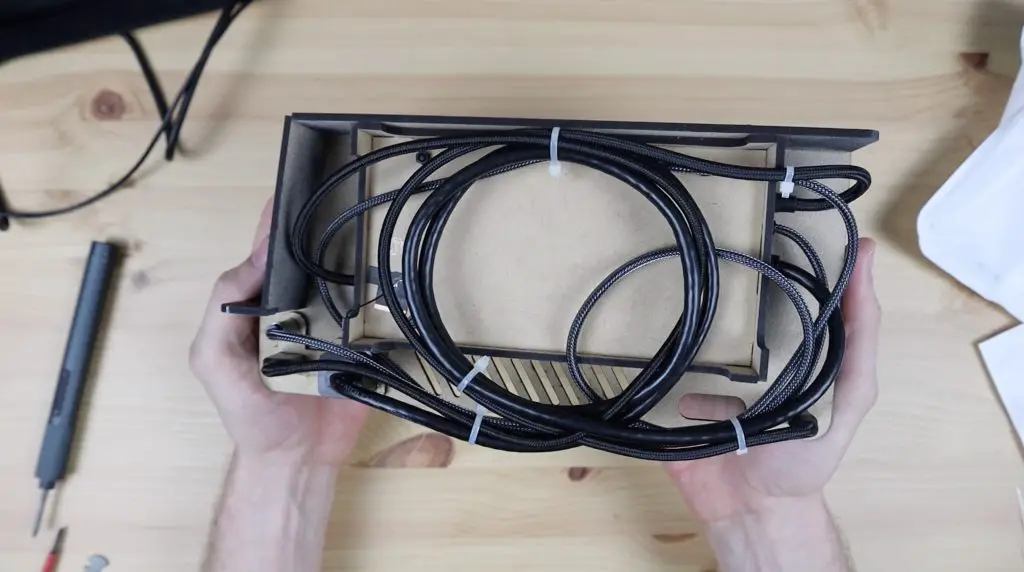
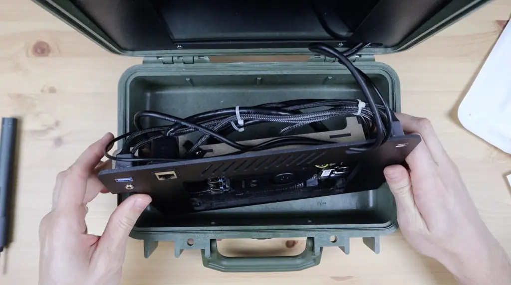
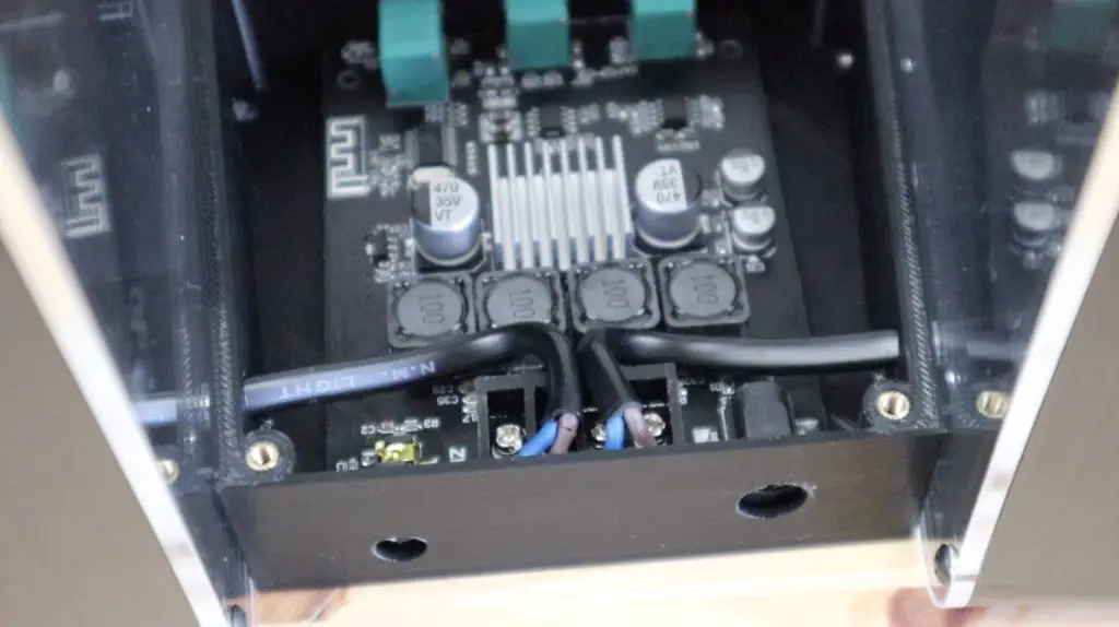
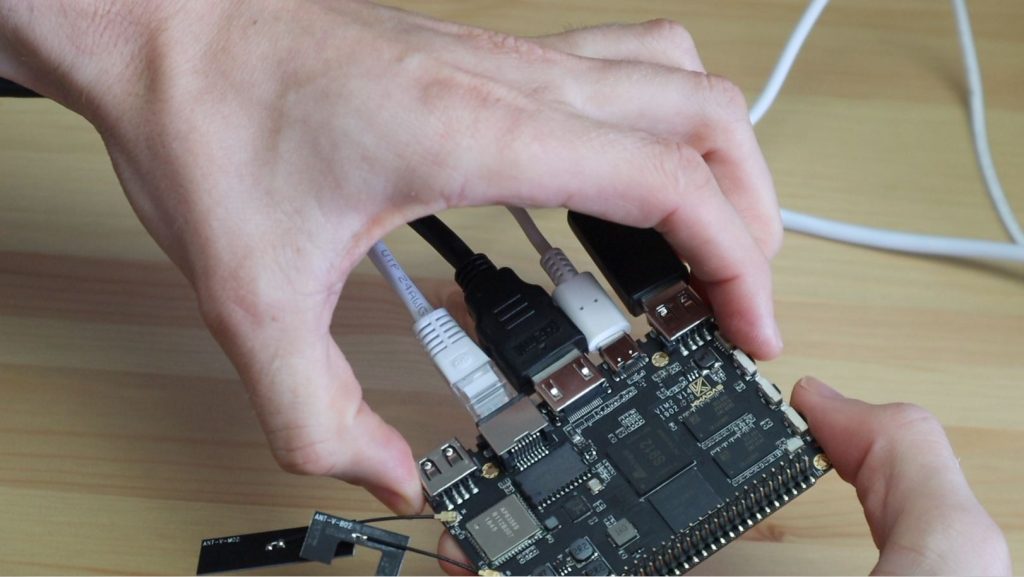
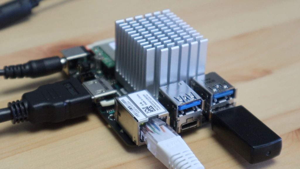
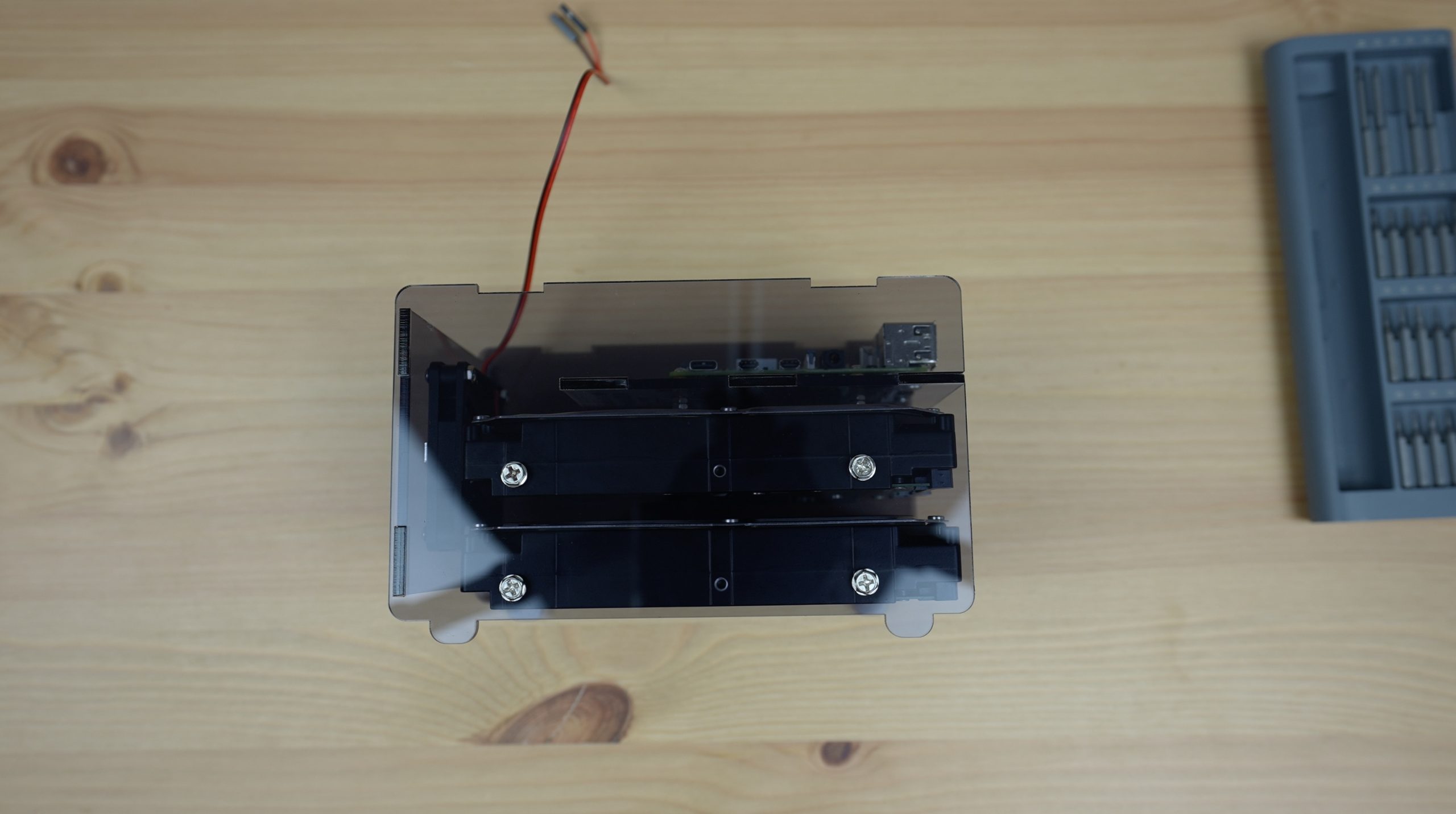
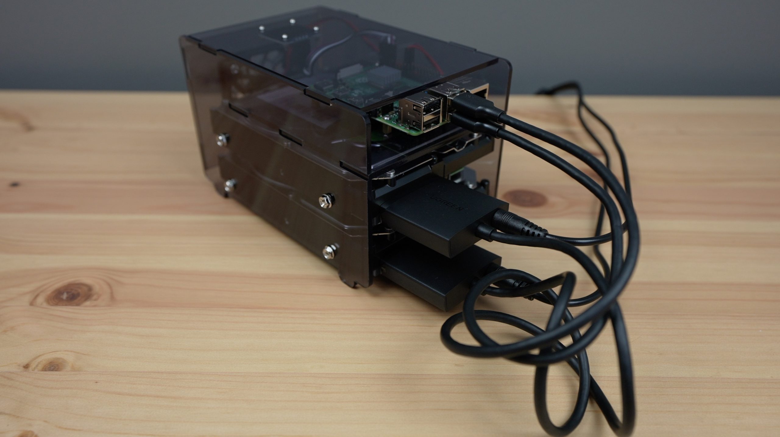
To finish it off, we need to plug a SATA to USB adaptor into each drive and connect these to our Raspberry Pi’s USB 3.0 ports, use the splitter and 12V power adaptor to provide power to our drives and finally, plug our power adaptor into our Pi. Depending on the power supply you’re using, you might need to use a 90 degree USB C adaptor to direct the cable toward the back of the NAS.
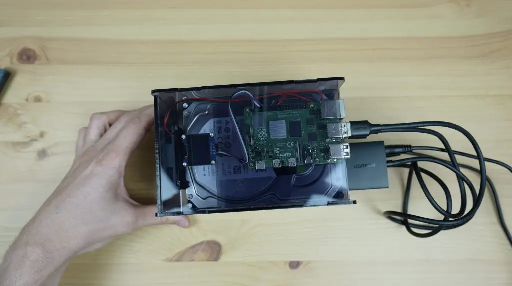
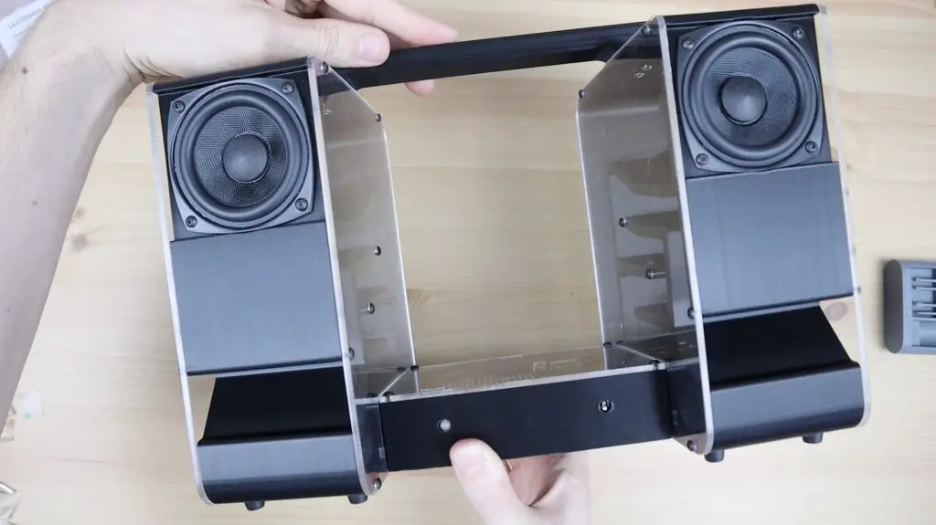
That’s the hardware part of our NAS build complete, so now we need to install and configure the software.
Installing and Setting Up Open Media Vault
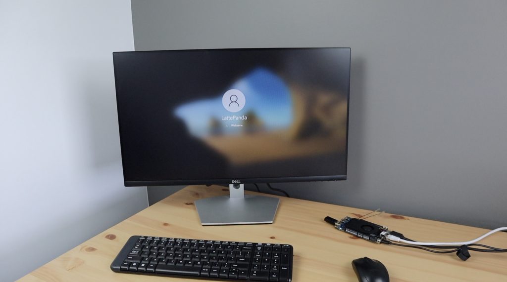
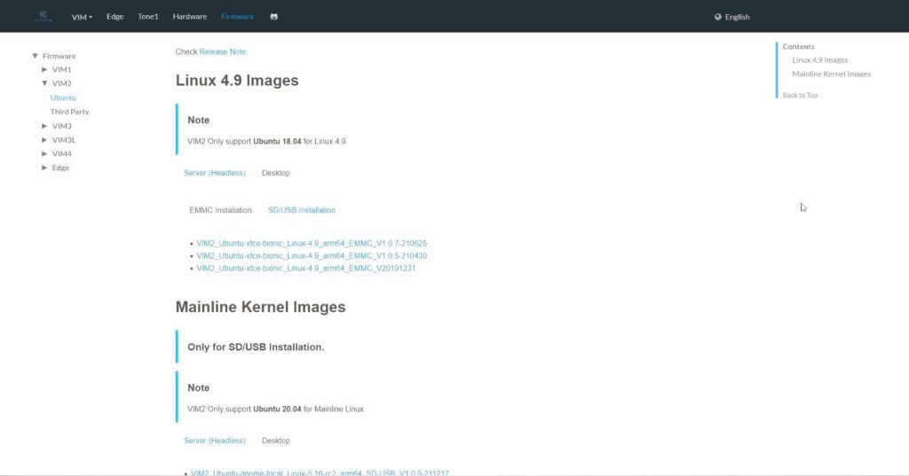
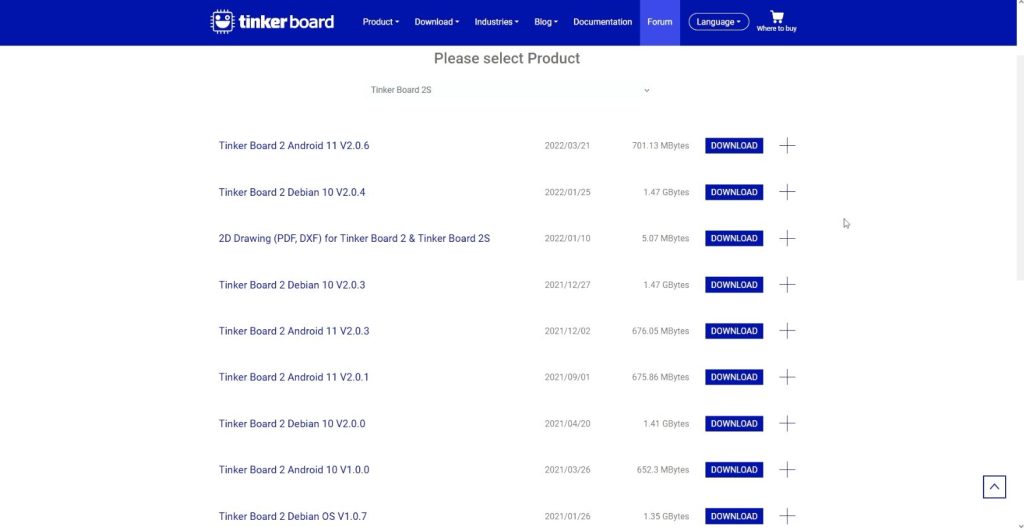
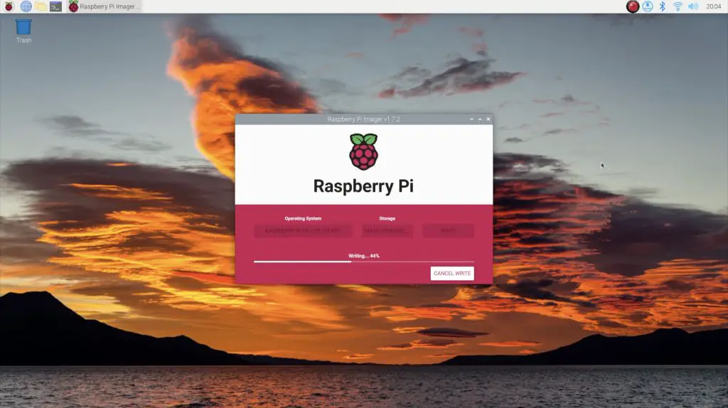
To start, we need an operating system for our NAS to run on. For this, we’re going to be using Raspberry Pi OS Lite. We can flash this onto using Raspberry Pi Imager.
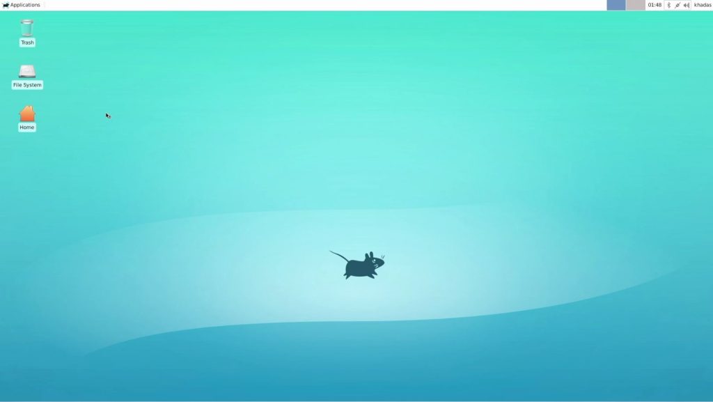
Choose Raspberry Pi OS Lite under alternate operating systems (OMV cannot be installed on the full desktop version, so make sure that you change to a Lite version), you can also give your Pi a new name, set up a username and password, your WiFi configuration if you’re going to be using WiFi to connect to your NAS and make sure that you enable SSH as we’re going to be setting the NAS up from another computer.
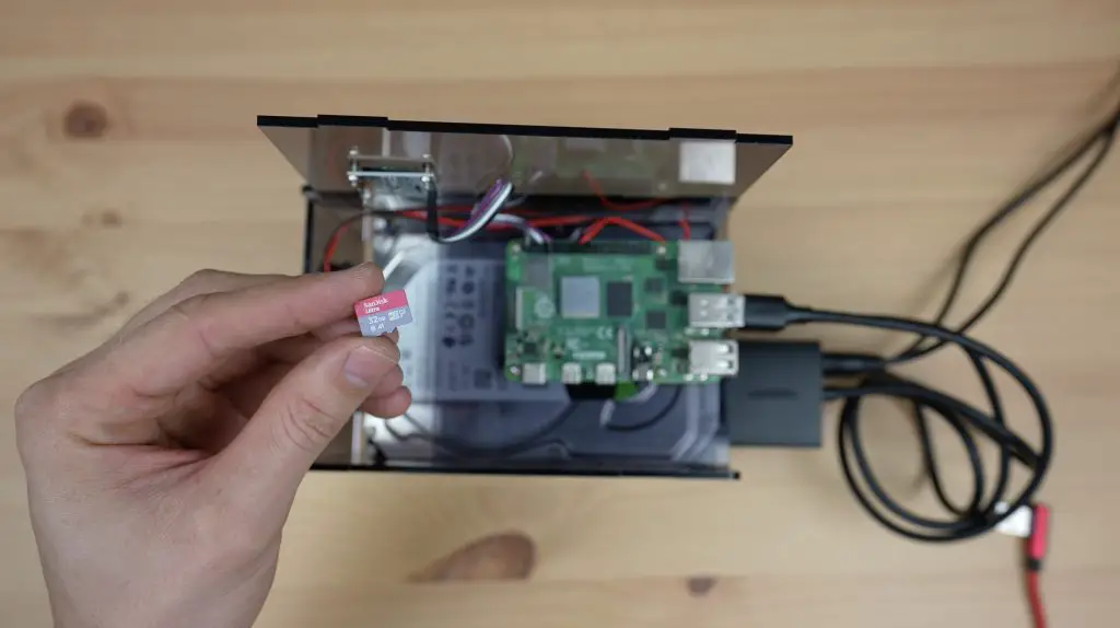
Insert the microSD card into your Pi and allow it to boot up. This usually takes around 5 minutes on a fresh install.
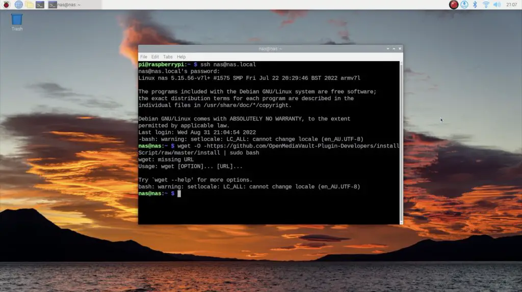
Once your Pi has booted up, we can SSH into it to continue the setup. You can do this on a windows PC using a utility like Putty or from another Pi using the following command:
ssh UserName@IPAddressOrHostnameObviously changing your username and pi’s name (hostname) to the ones set up in the imager. So for my NAS, I used:
ssh nas@nas.localYou’ll be prompted to enter the password for the username you just set up, then you’ll be able to enter terminal commands.
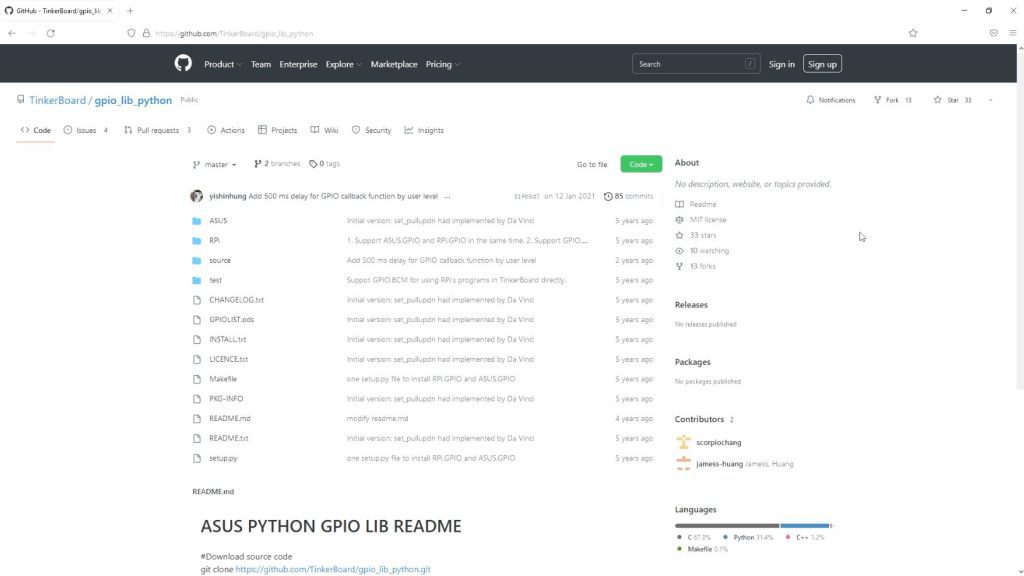
We’ll start by setting up the OLED stats display using my display script. Following the commands in this guide to set it up, starting with the updates. Each time you reboot your Pi, you’ll need to ssh into it again once booted to continue setting it up.
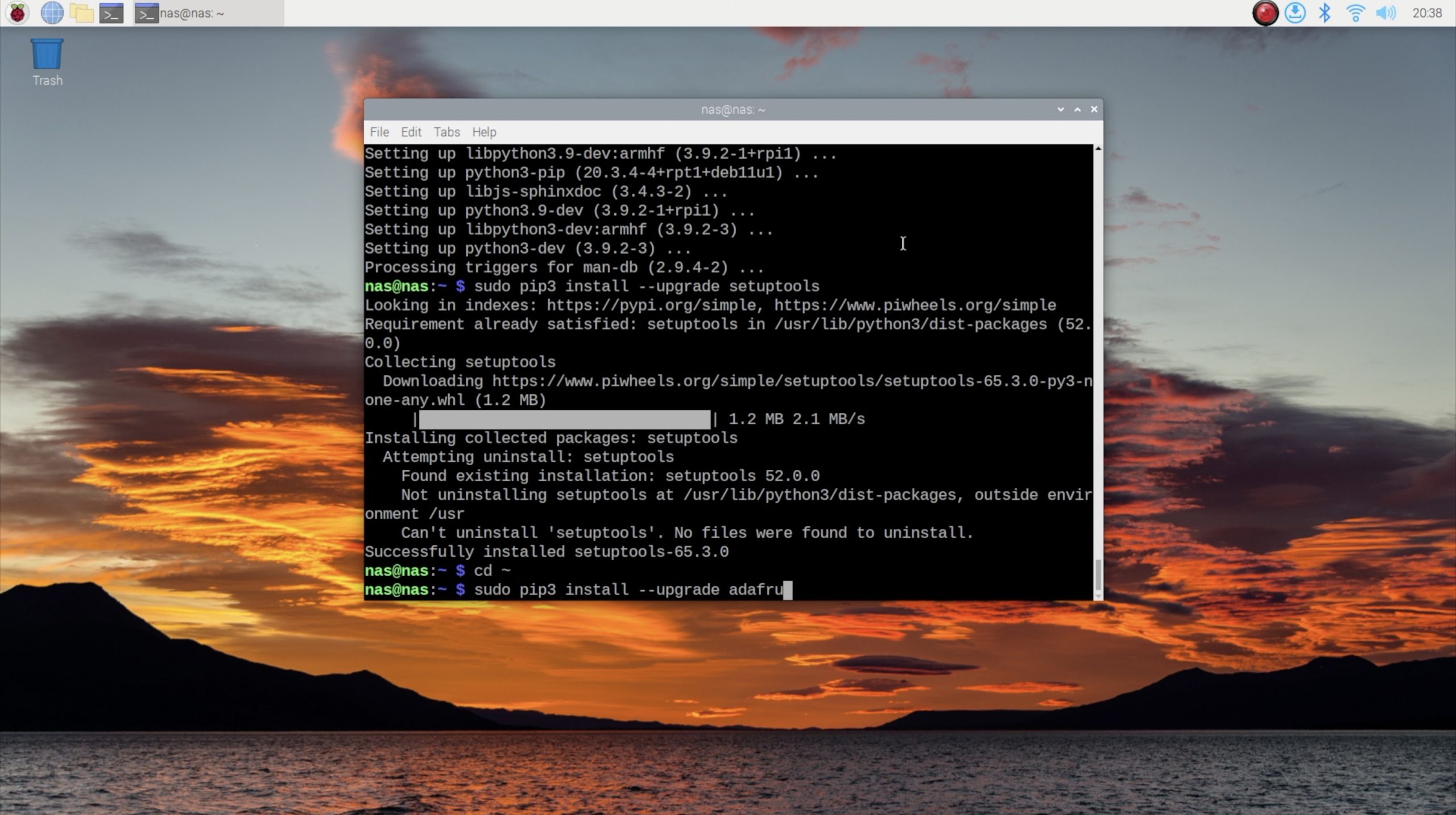
Next, we can move on to installing Open Media Vault or OMV. This is done with a single line:
wget -O - https://github.com/OpenMediaVault-Plugin-Developers/installScript/raw/master/install | sudo bashThis script may take up to 30 minutes to run through and will end with your Pi requiring to be rebooted.
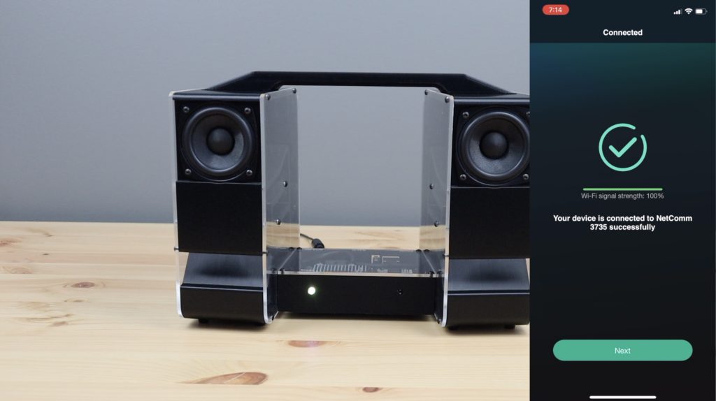
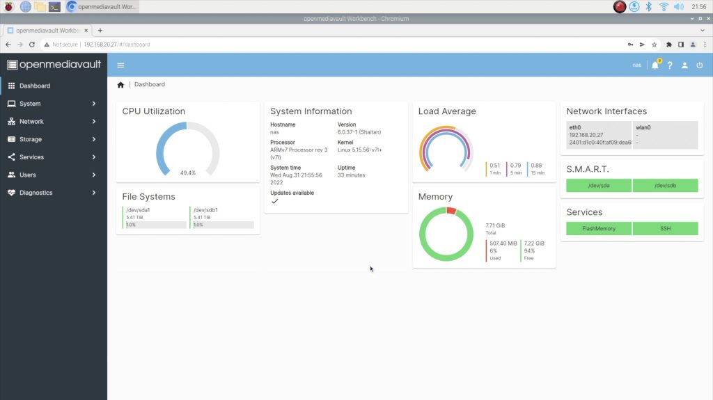
Once that is up and running, we can access our NAS through a web browser by going to the IP address shown on the OLED display. It’s also a good idea to set this up as a fixed IP address on your network as well, this will ensure that your NAS is given the same address each time it boots and will make it easier for the other computers on your network to find it. This is typically done through your router’s configuration interface but differs from brand to brand.
Log in to your NAS using OMV’s default username “admin” and password “openmediavault“.
The following instructions for the configuration of the NAS are quite high-level and assume that you’ve got some familiarity with OMV or other file-sharing packages, but should be sufficient to help you get started.
From the OMV web interface, you’ll probably be prompted to set up your dashboard. This doesn’t matter too much but just allows you to set up what information is displayed when you log in to the web interface. Choose which items you’d like to see on your dashboard and then click on save.
The first thing you’ll want to do is to click on the gear in the top right and change your password to something other than the default.
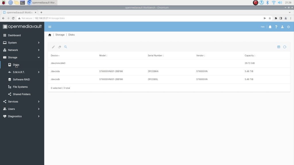
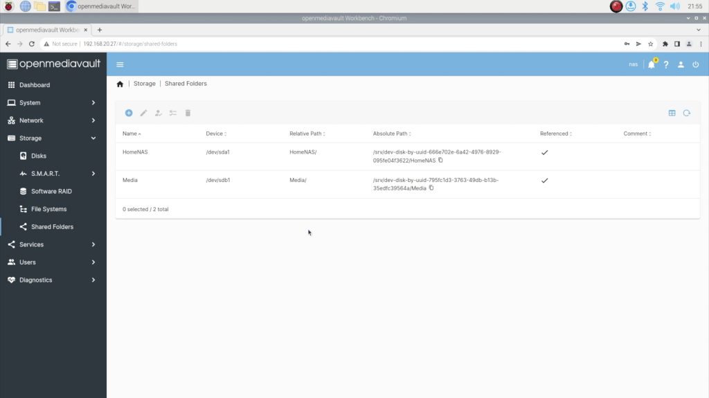
Next, click on Storage in the menu on the left and then go to Disks. Both of your connected drives should show up here. If they don’t then shut the NAS down, check your connections and try again.
If both of your drives show up, then click on File Systems in the menu on the left again and then click on the small plus sign to create a new file system.
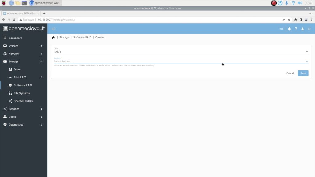
Ideally, we’d want to use the two drives in a RAID 0 or RAID 1 configuration so that we’ve got a single storage volume and potentially some redundancy, but OMV and most other packages don’t support RAID across USB-connected drives, so we’ll only be able to set them up as two separate storage volumes.
I’ve created one volume for my documents and files and then one for media like music, photos and videos.
You’ll need to select your drive and the file system type – EXT4 is fine for most setups. You’ll then be asked to mount your new file system. You’ll notice a yellow bar at the top asking you to apply your configuration changes. You can do this as you go or all right at the end, it doesn’t really matter. I like to do it as I go through each step.
Once we have a File System, we then need to create a Share Folder, so click on that menu option on the left. Click on the small plus sign to create a shared folder, then give it a name and select the File System you’d like to create it on. Leave the other fields as their defaults.
The last thing that we need to do is activate the SMB service so that our folder is accessible over our network. We do this by going to Services, then SMB/CIFS (Server Message Block / Common Internet File System), then clicking on settings and toggling it to Enabled. The other fields can be left as defaults.
Then go back to SMB/CIFS and click on shares to create a share, toggle to Enabled and select the folder that you’d like to share over the network. You can also set permissions to allow Guests (users who haven’t logged in) to access the folder or require all users to log in (using their OMV username and password) to access the shared folder. Click on save, then accept the configuration changes at the top (yellow bar) and your NAS is then ready to be accessed on another computer.
It’s a good idea to set up users and roles as well, but for the purpose of this guide, the NAS is now usable on your network.
How To Access Your NAS On Your Network
The way in which you access your NAS on your network will depend on what device you’re accessing it from and what operating system it is running.
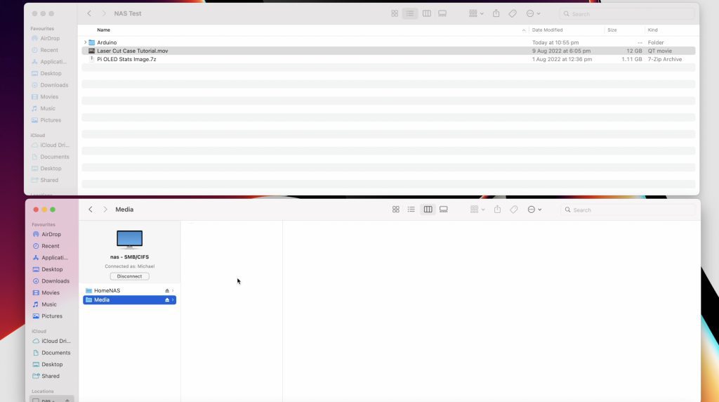
On a Mac, open up Finder then click on Go and Connect to Server. Enter the path of the network drive that you’re trying to map and then click on connect. You might be asked to enter login details, then click on Ok to mount the drive.
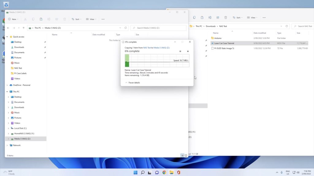
On Windows 10, open File Explorer, click on This PC from the left panel, then Computer from the tabs at the top and then Map Network Drive. Select an available drive letter, enter the path of the network drive that you’re trying to map (or use the Browse function) and then select Finish.
Let me know what you think of my Raspberry Pi NAS in the comments section below, or if there are any changes you’d like to see made to the design. Also, check out my comparison between this DIY NAS and the Asustor Drivestor 4.