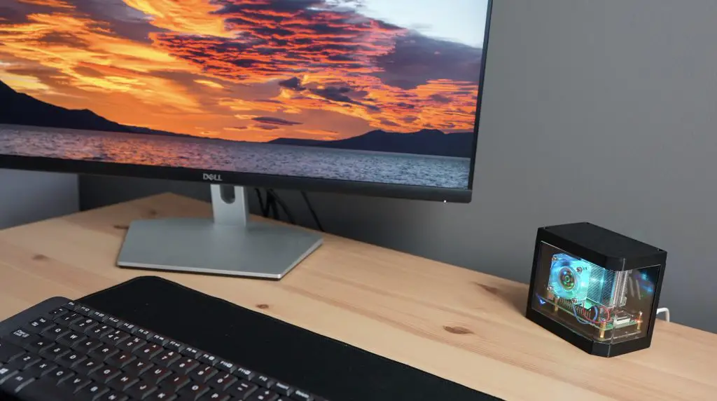
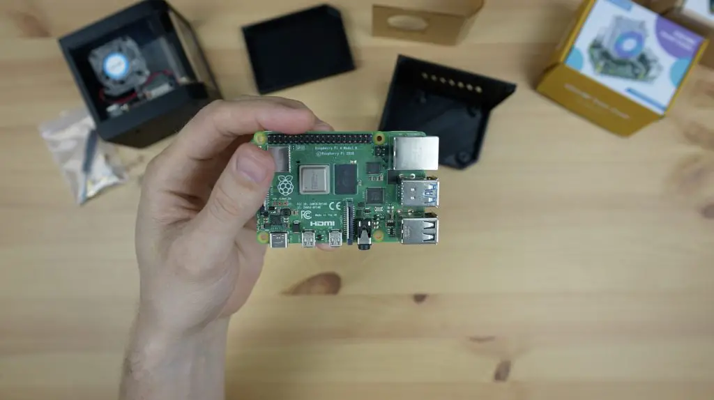
Every time I’ve made a new case for my Raspberry Pi, there are always a few comments suggesting adding another fan or making improvements to the cooling, so today I’m going to put these suggestions to the test by building a case that has as many fans as possible to find out if more fans really result in lower CPU temperatures.
Now this wouldn’t be a test without some sort of data to compare it to, so we need a baseline to see what the CPU temperature is in my usual Pi case design.
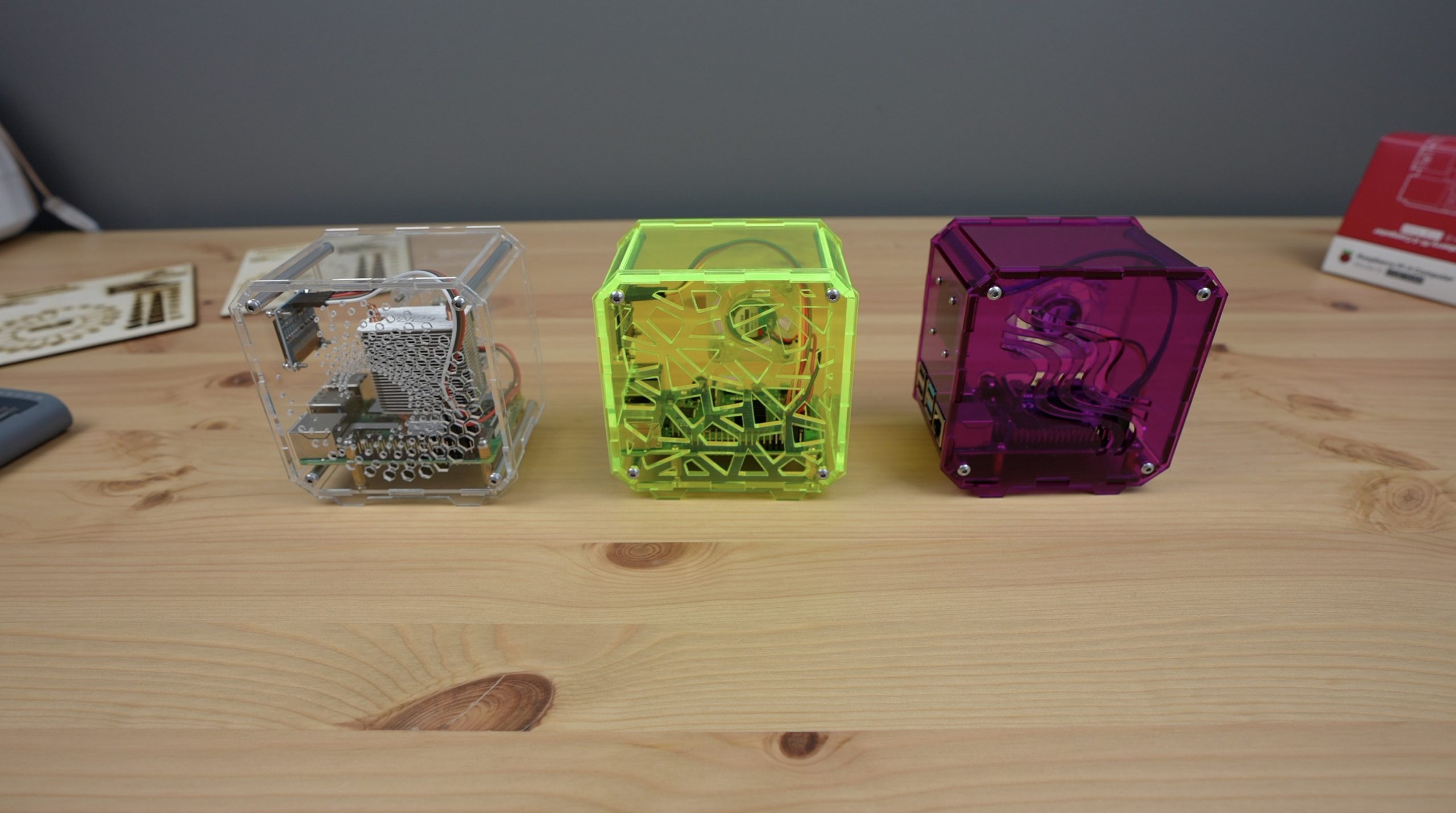
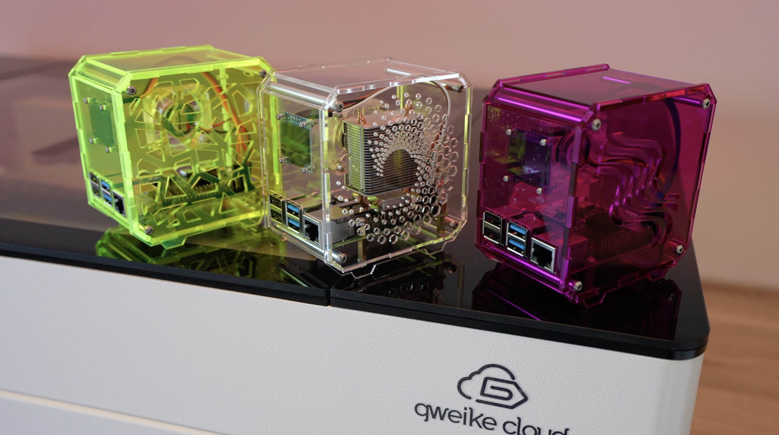
I’m going to be comparing three configurations;
- A baseline small heatsink placed onto a Pi in my standard desktop case design with a fan on the side panel,
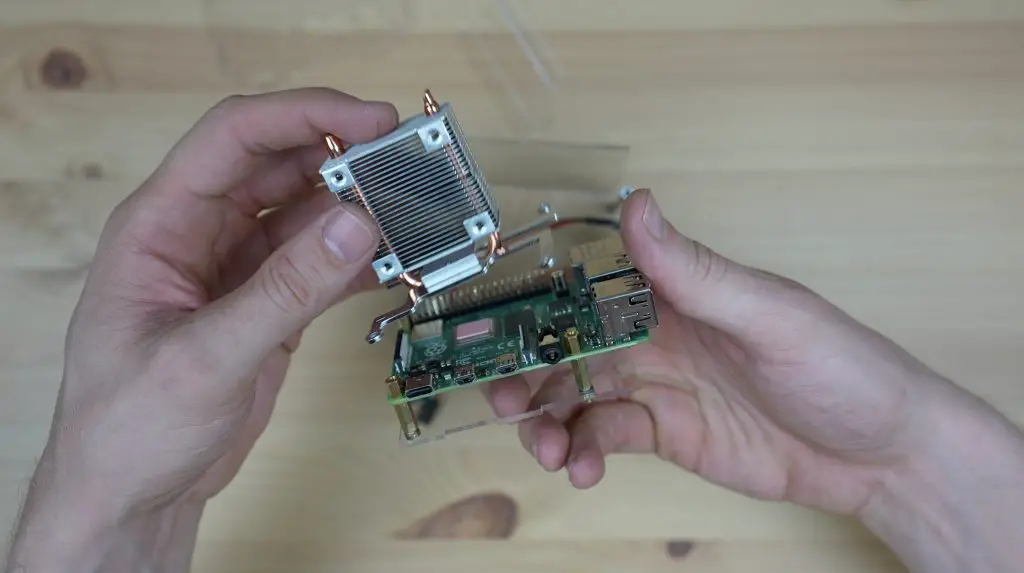
- An Ice Tower cooler on the Pi like I use in most of my designs,
- An Ice Tower cooler in a case where every possible space is filled with a fan.
I’m going to run each test at the Pi’s base frequency of 1.5Ghz and I’ll then overclock the Pi to 2.2Ghz and see how that affects the temperatures.

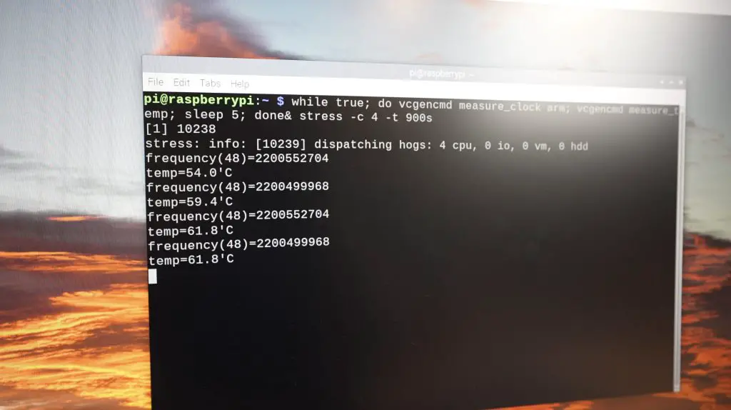
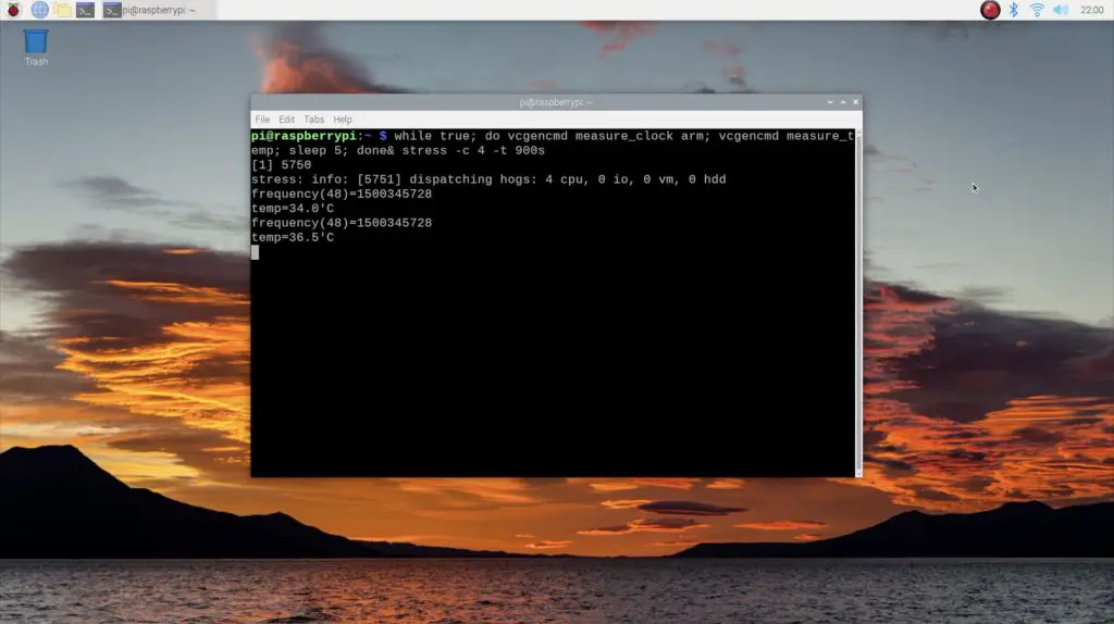
For each, I’ll be starting at room temperature, which is about 25 degrees, and I’ll run a utility called CPU burn which maxes out the Pi’s four cores and I’ll leave this running until the temperature stabilises or we start thermal throttling.
Watch my video of the build and test below or read on for the write-up;
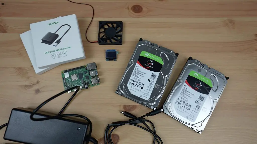
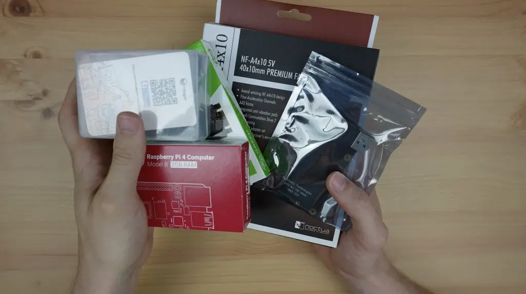
What You Need For This Project
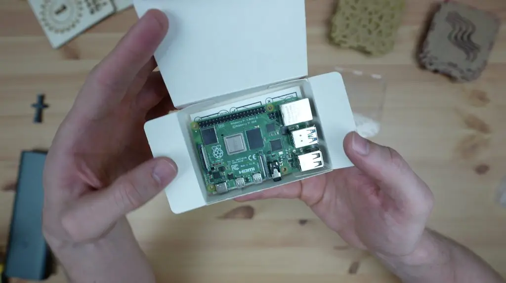
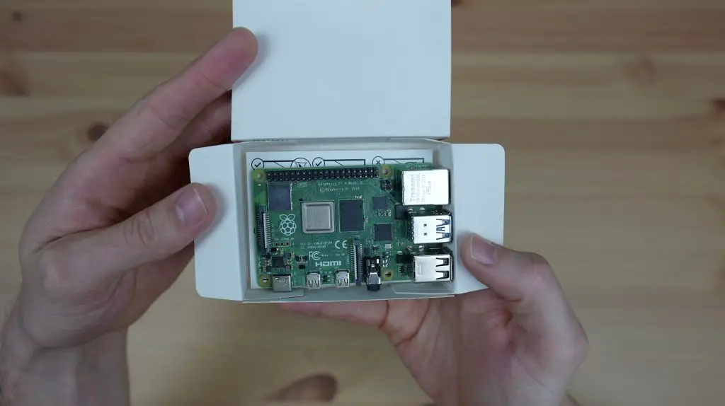
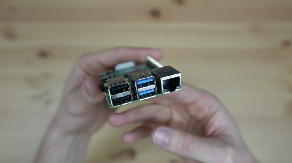
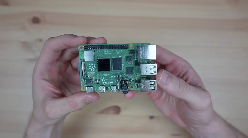
- Raspberry Pi 4B – Buy Here
- Ice Tower Cooler – Buy Here
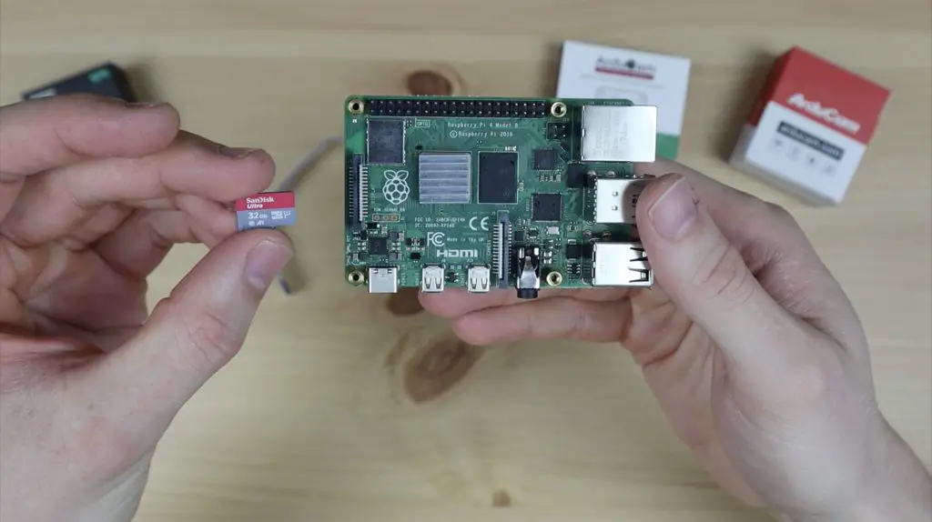
- 32GB Sandisk MicroSD Card – Buy Here
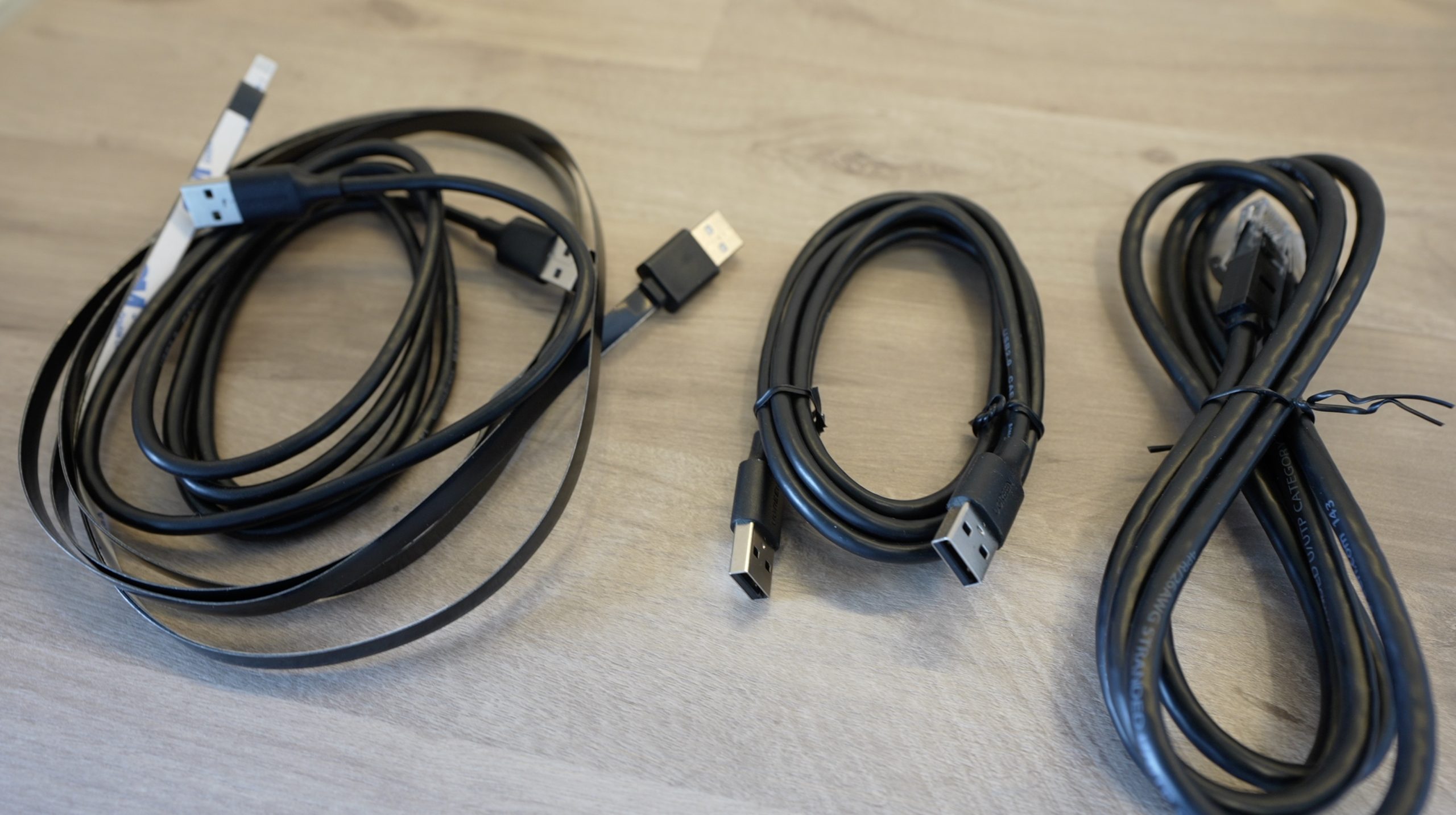
- 90-Degree Micro HDMI Cable – Buy Here
- 90-Degree USB C Cable – Buy Here
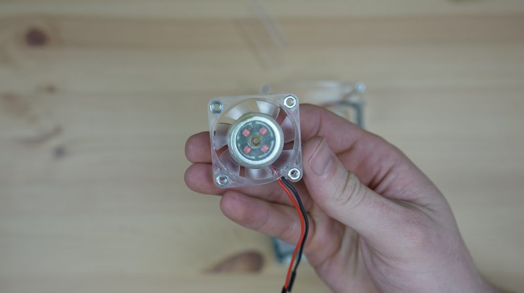
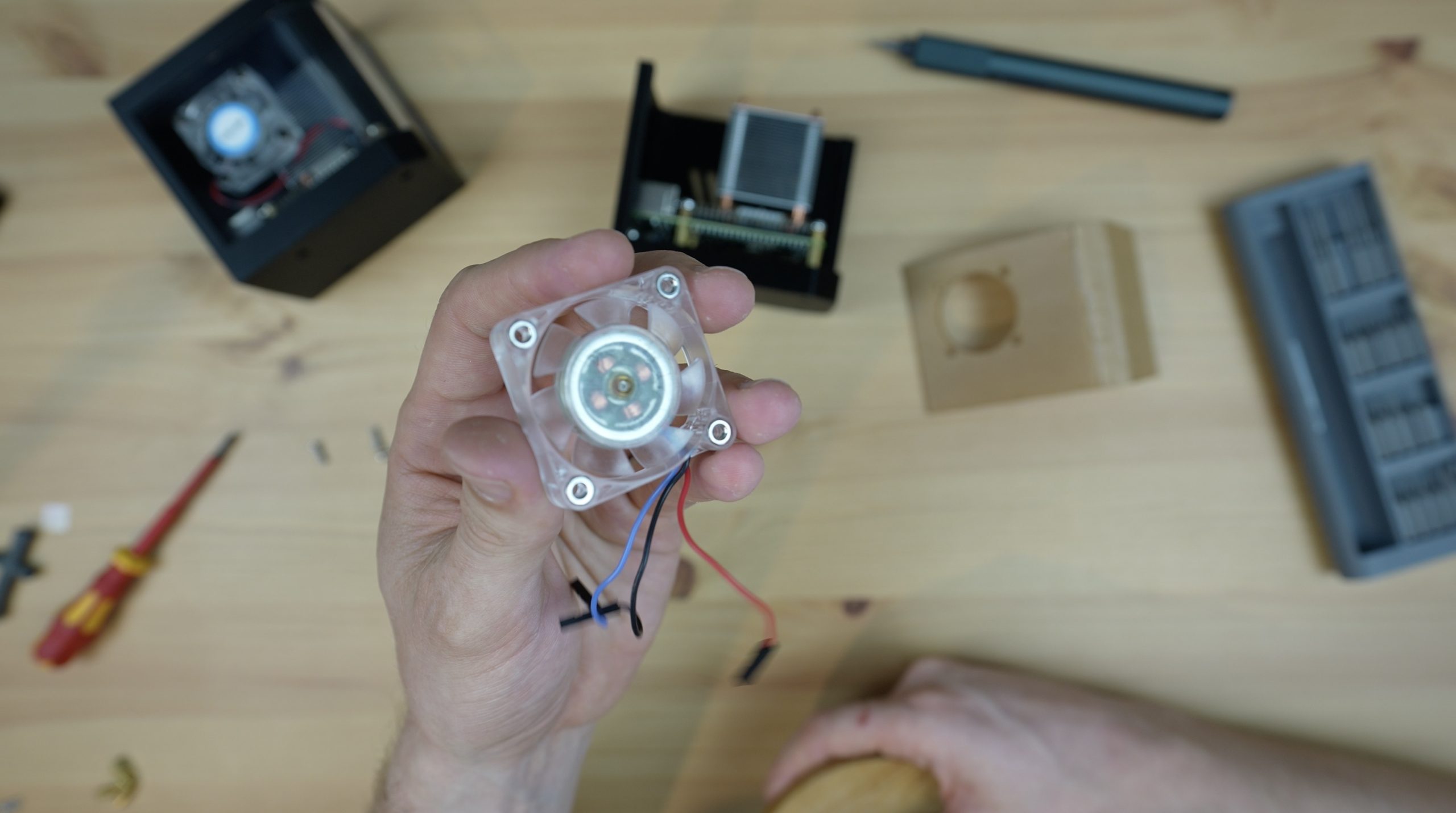
- 5V 40mm RGB Fans – Buy Here
- Breadboard Jumpers – Buy Here
- Pin Header Strips – Buy Here
- M3 Brass Standoffs – Buy Here
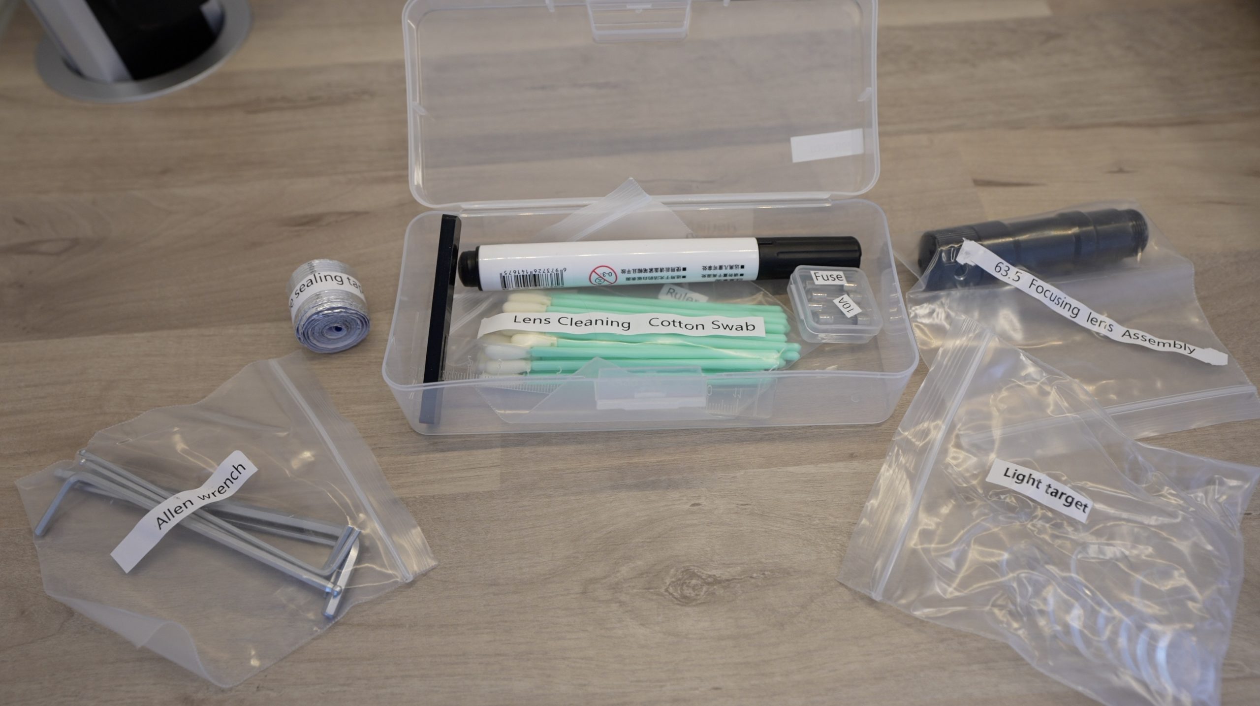
Equipment Used
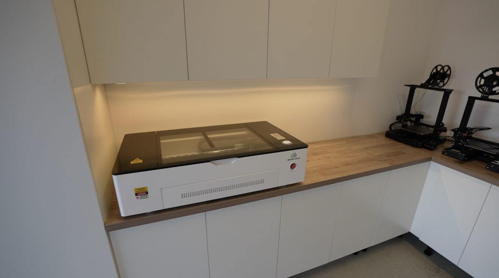
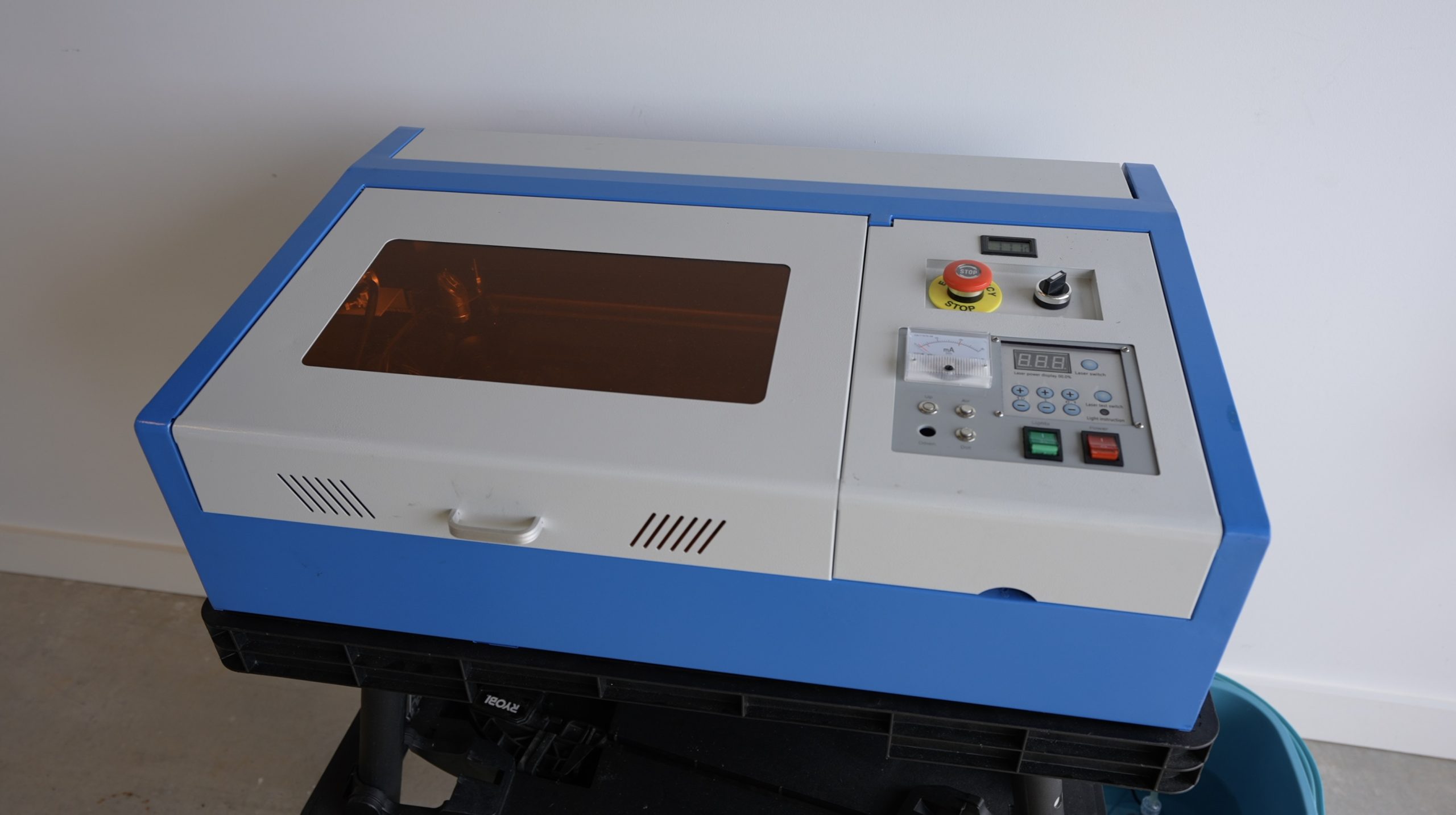
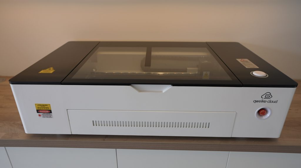
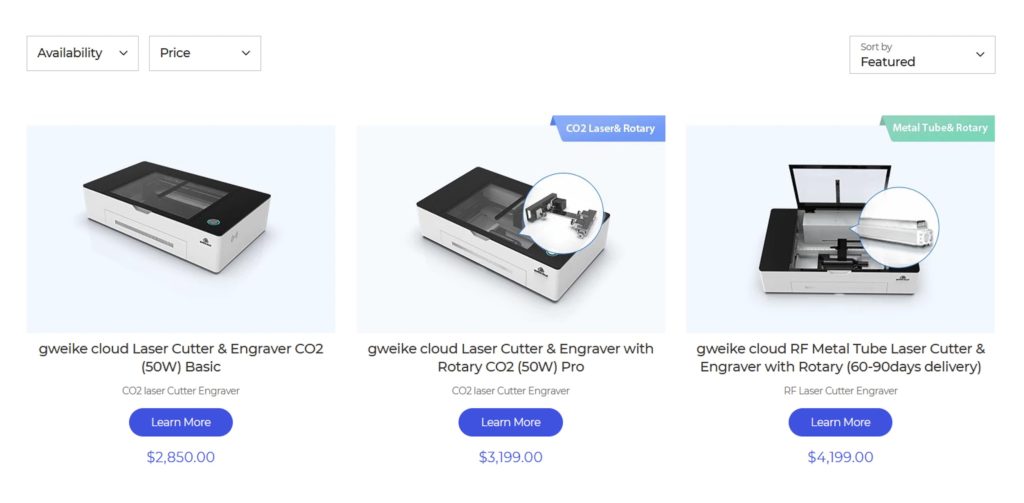
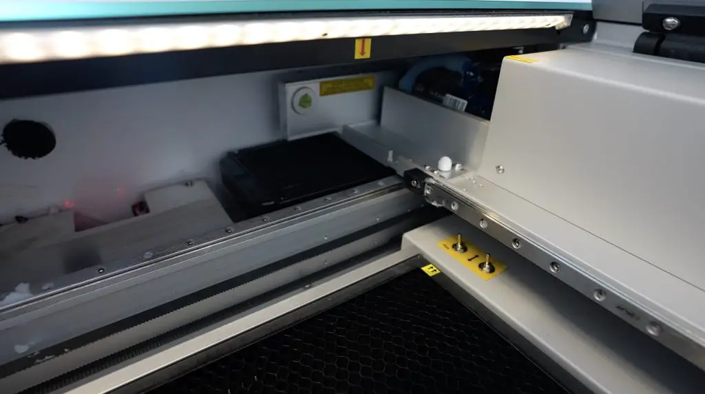
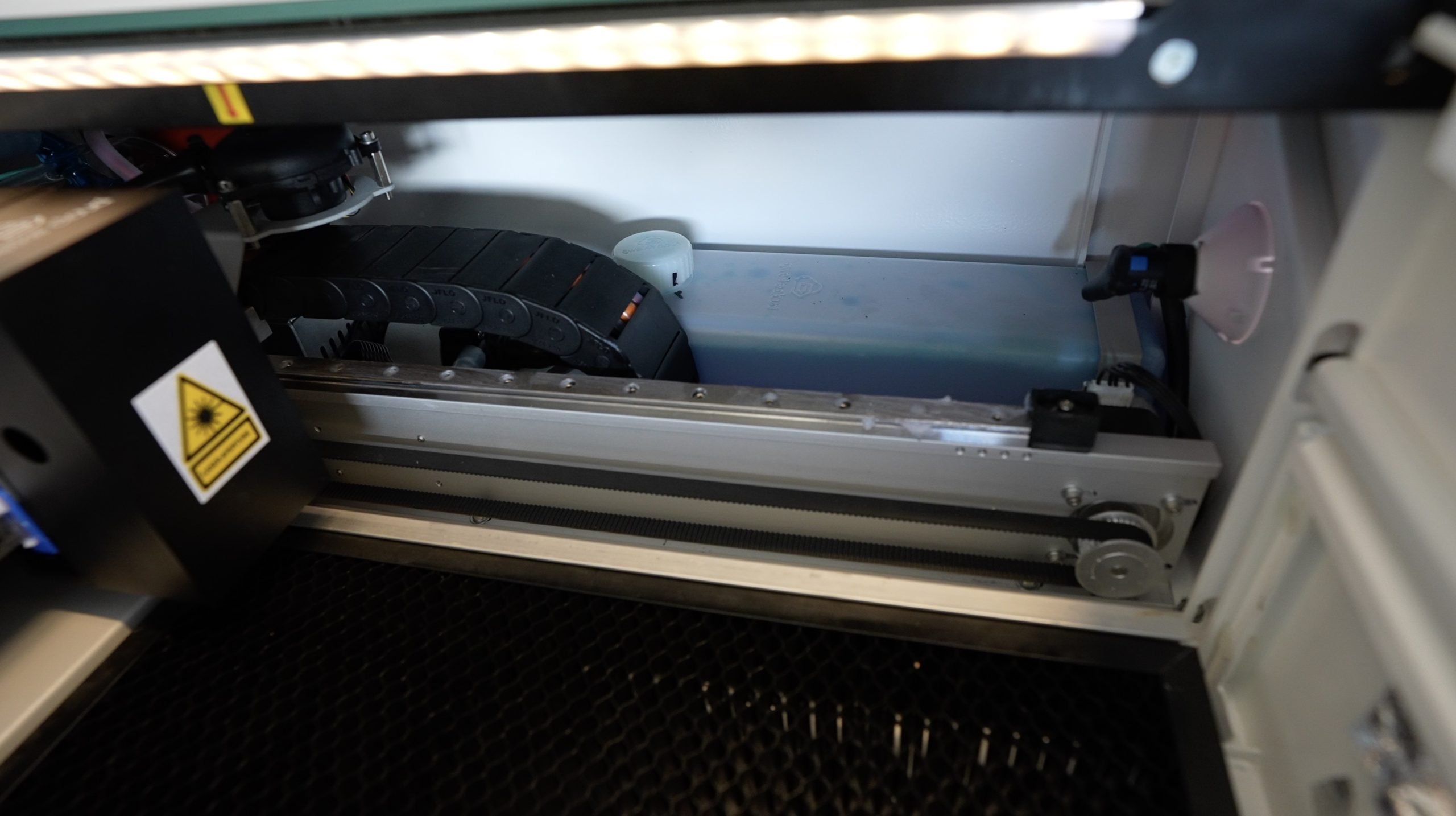
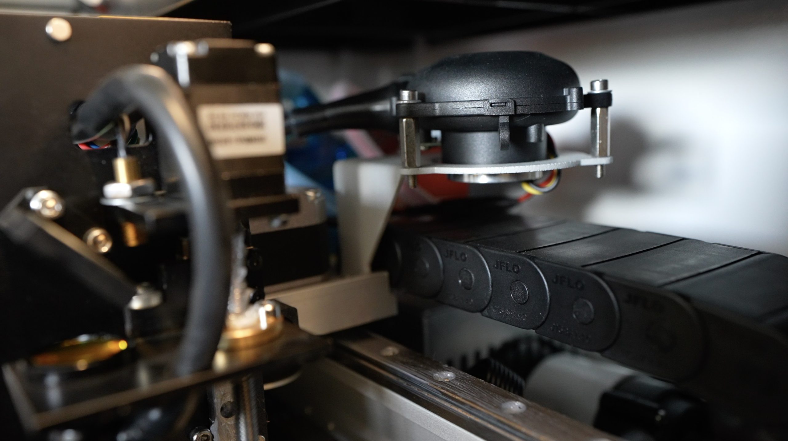
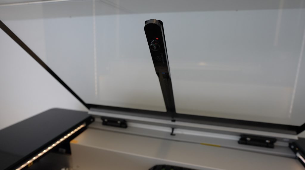
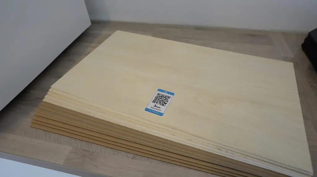
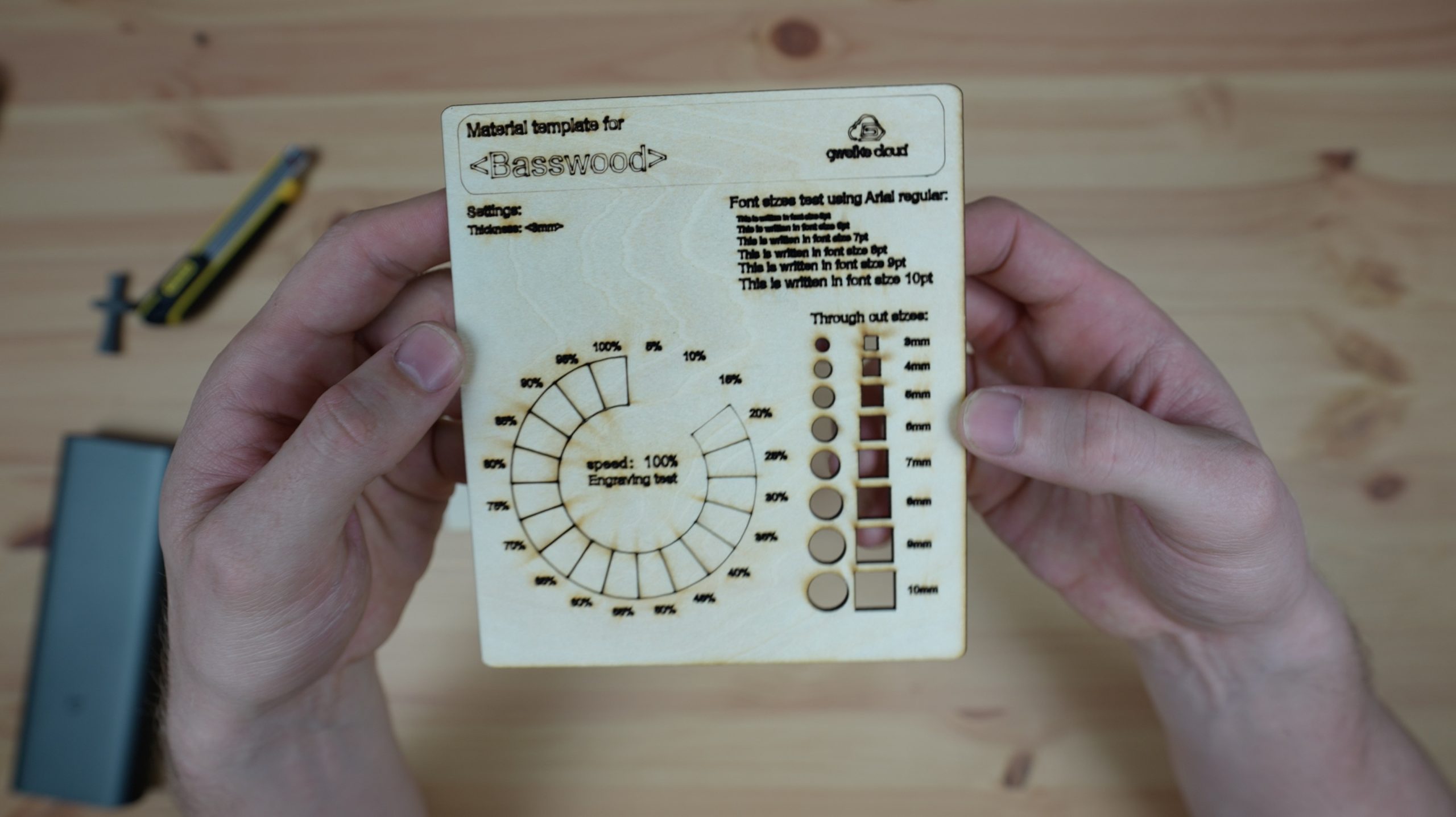
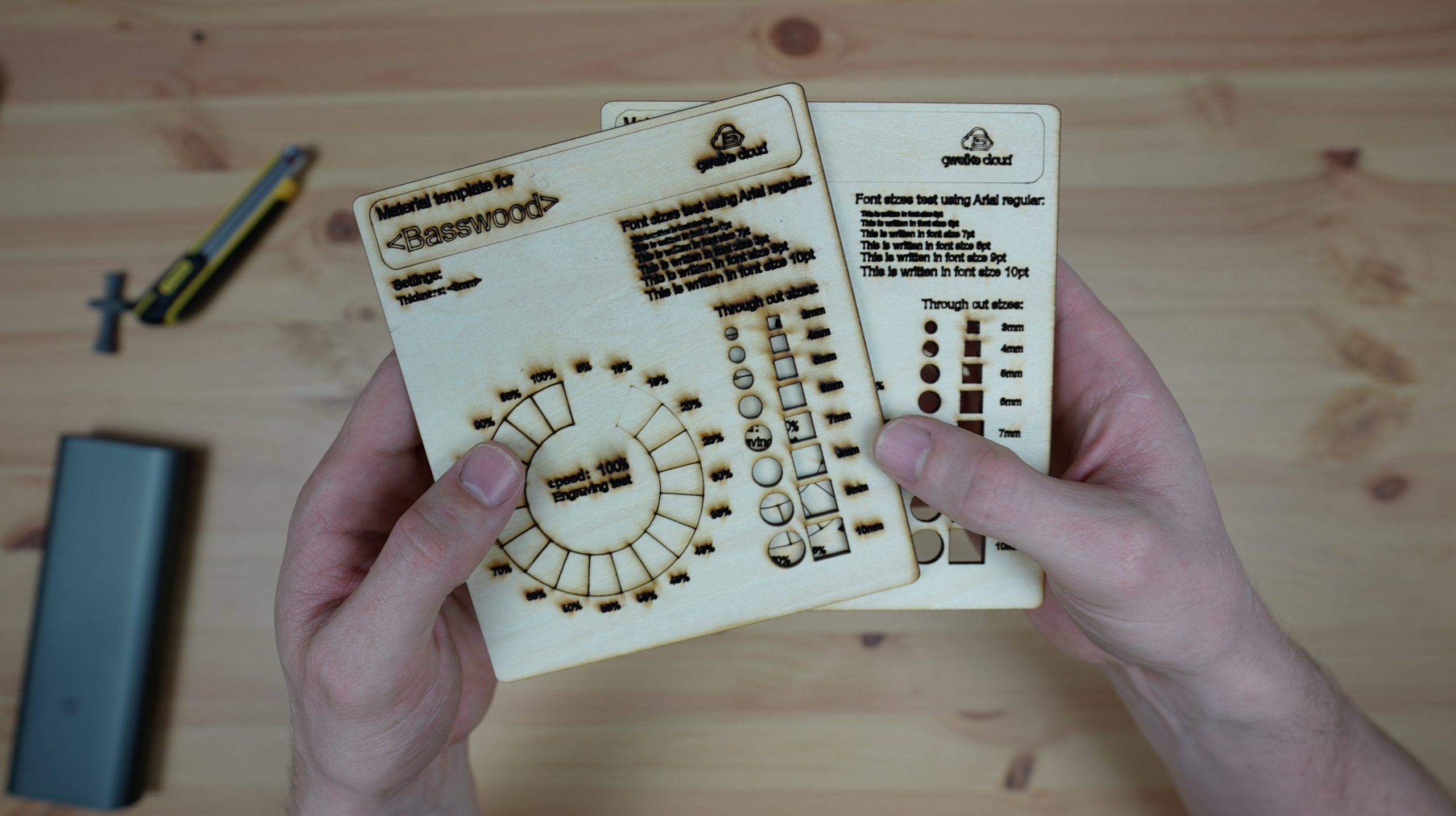
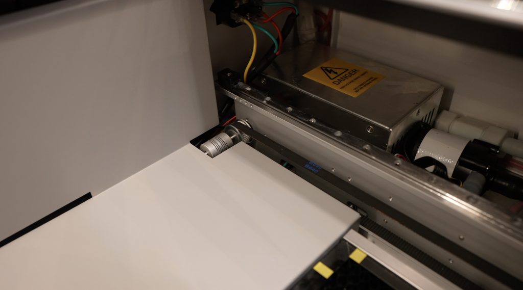
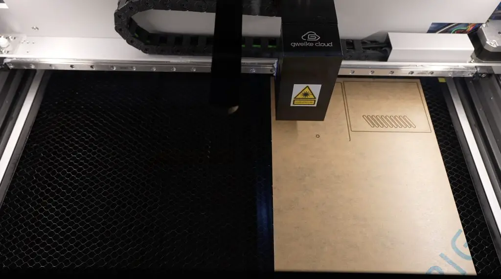
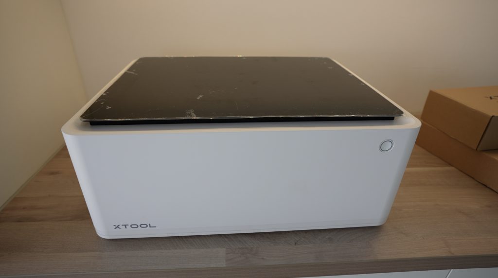
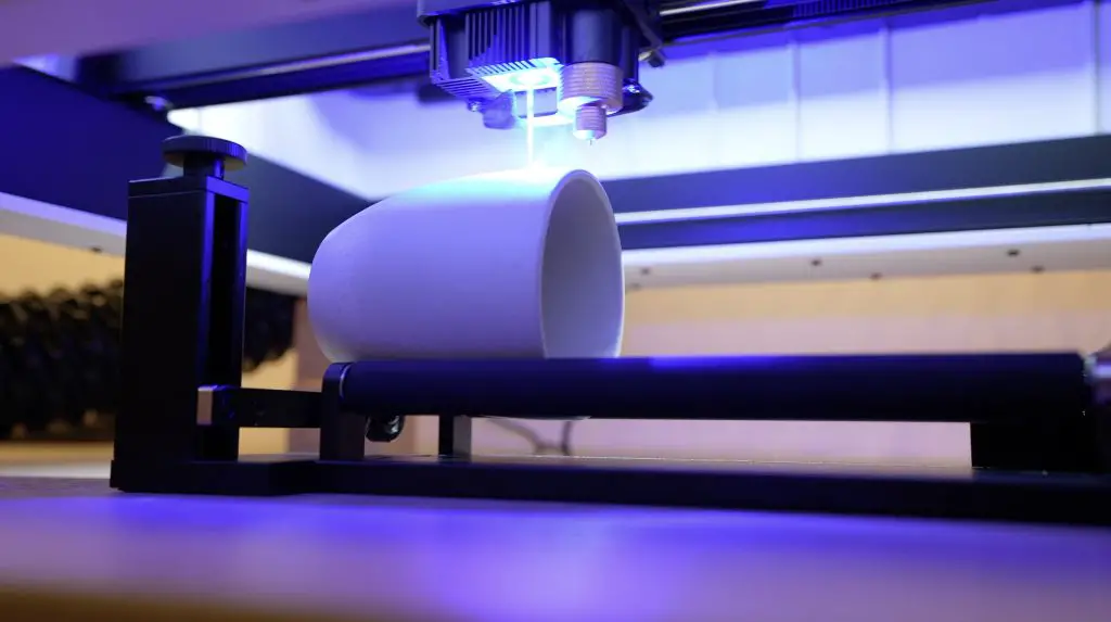
- Gweike Cloud Laser – Buy Here
- Use my discount code MK200 on checkout to get $200 off
- Electric Screwdriver – Buy Here
- Acrylic Bender – Buy Here
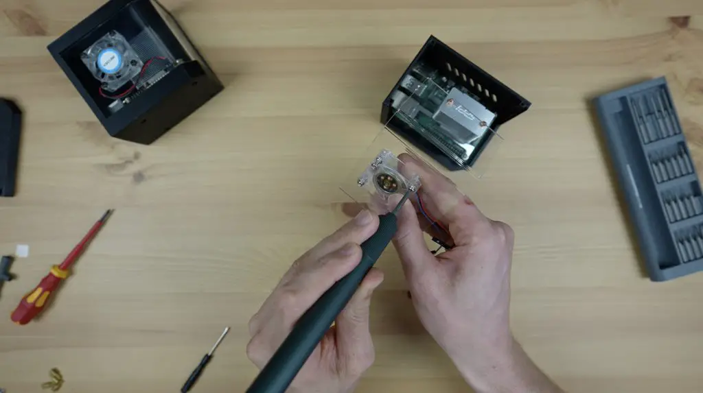
- TS100 Soldering Iron – Buy Here
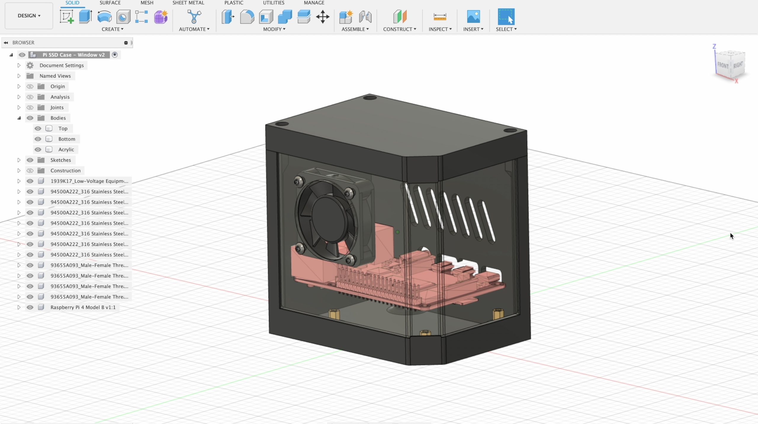
Designing The Fan Case
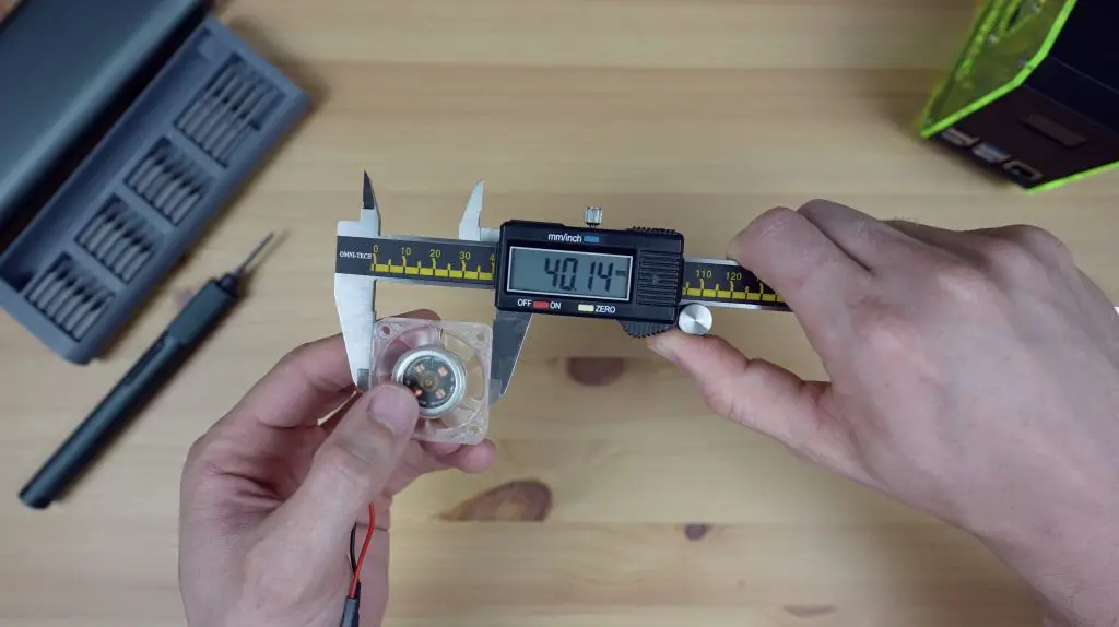
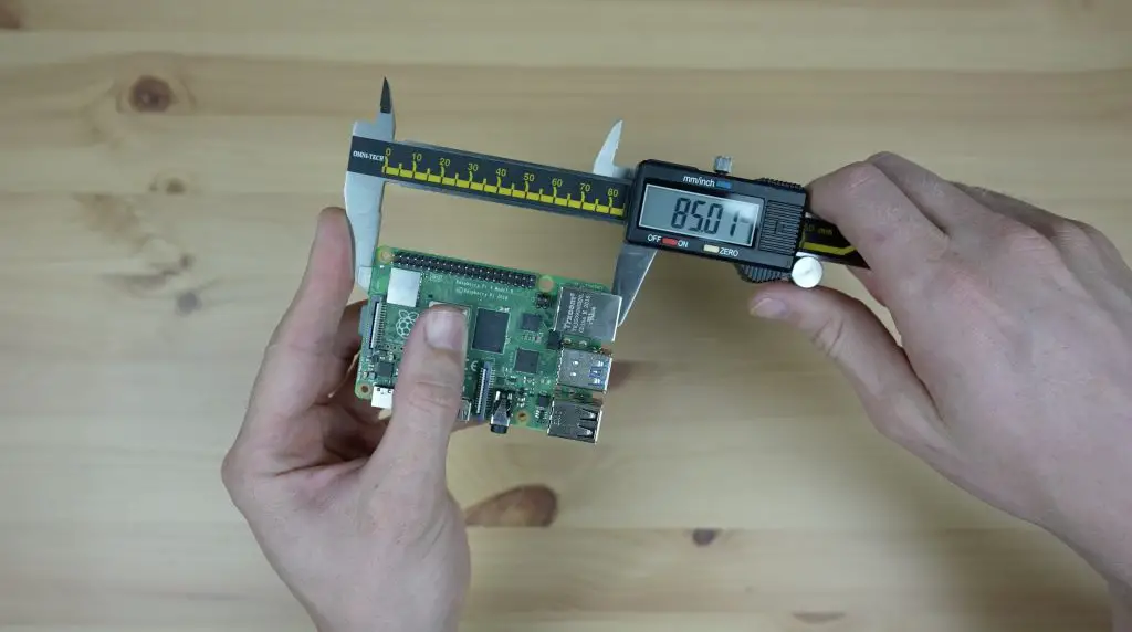
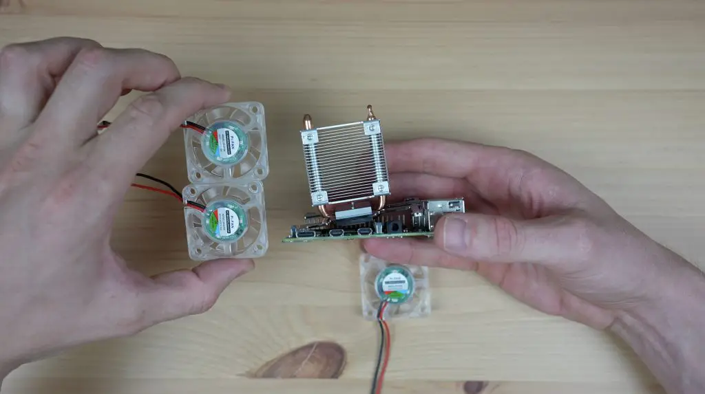
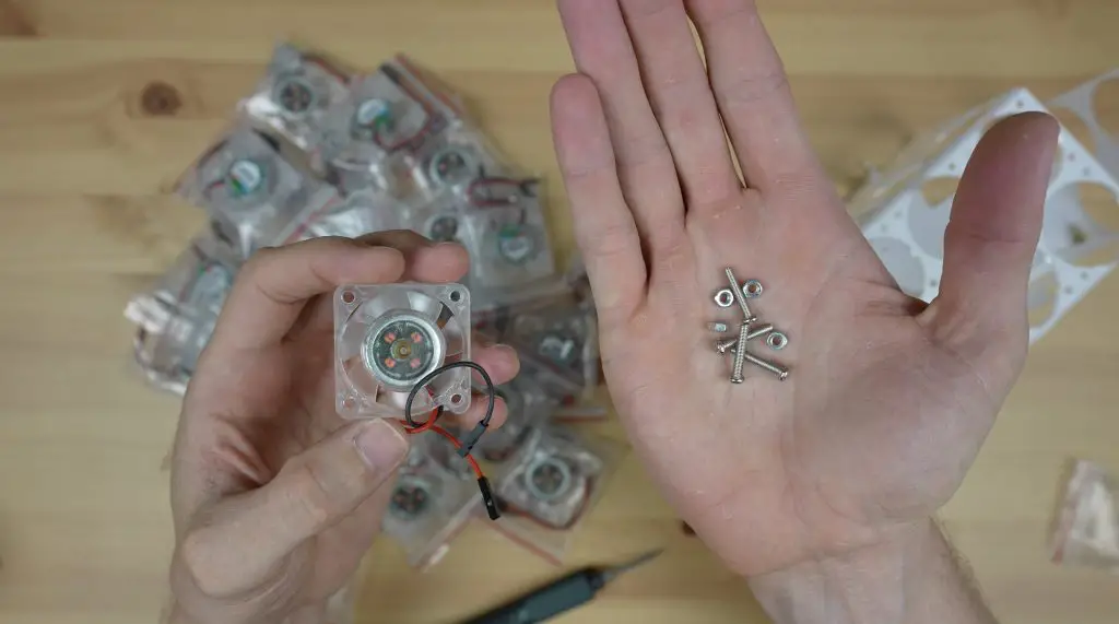
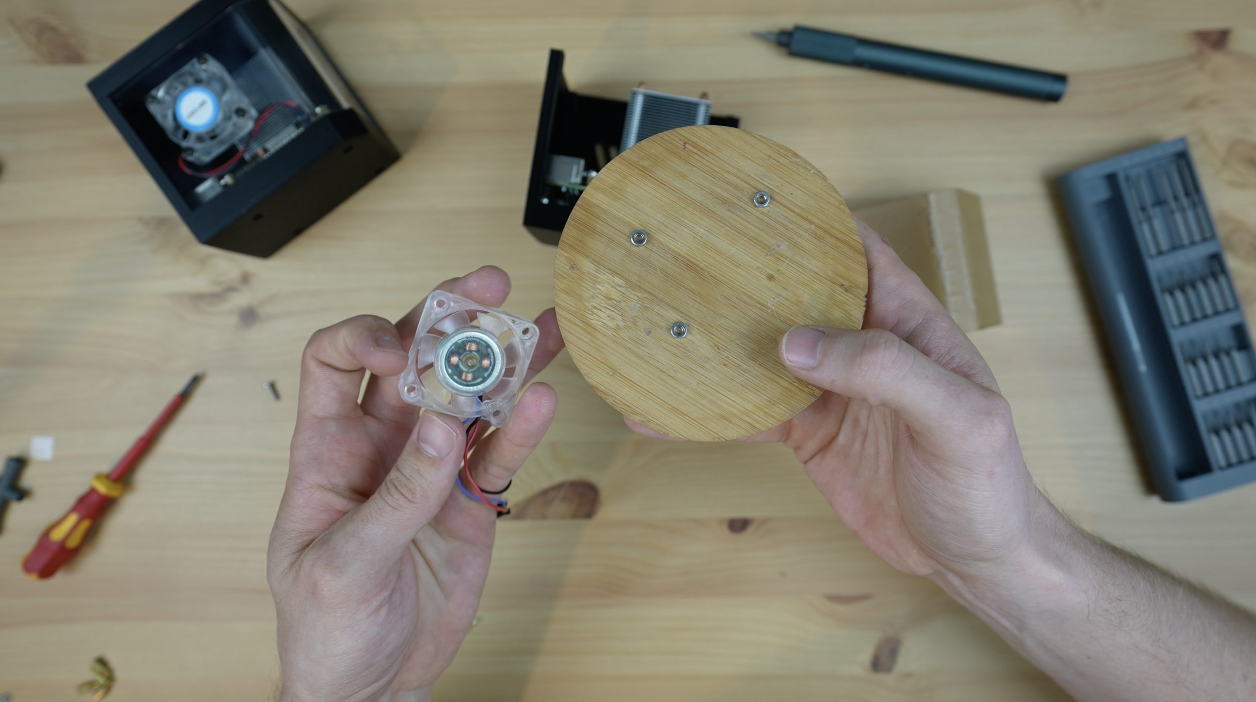
To start off, I had to work out how many fans I’d need. Each fan is a square of 40mm and is 11mm deep, and a Raspberry Pi is 85mm long and 56mm wide.
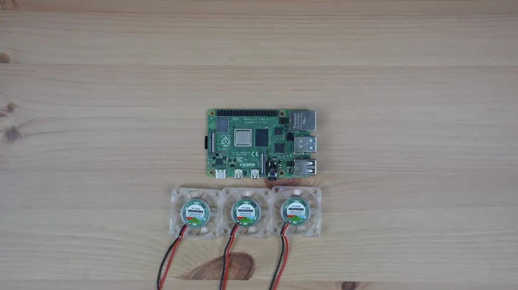
So to cover the full length of the Pi with the SD card sticking a little out the back we’re going to need 3 fans, and to cover the width we’ll need 2 fans. We also need a bit of height to leave space for the Ice Tower on top of the Pi, so I’m going to make it two fans high. I’m not going to put any fans underneath the Pi as they’re restricted by the desk and there is nothing to cool on the bottom.
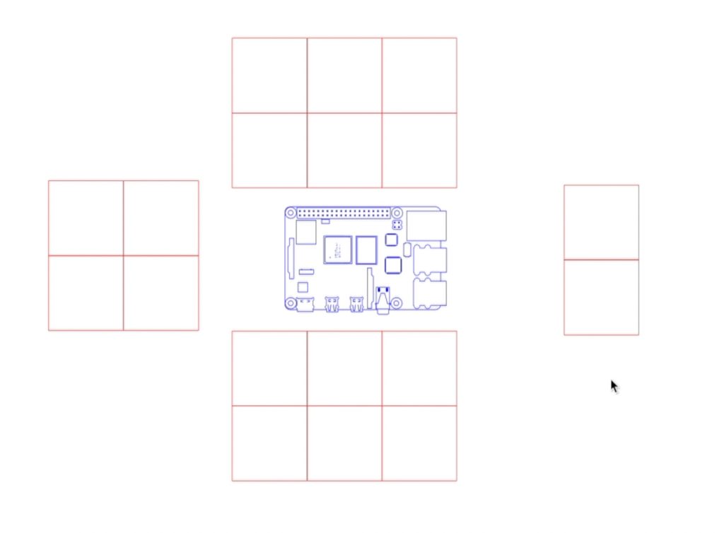
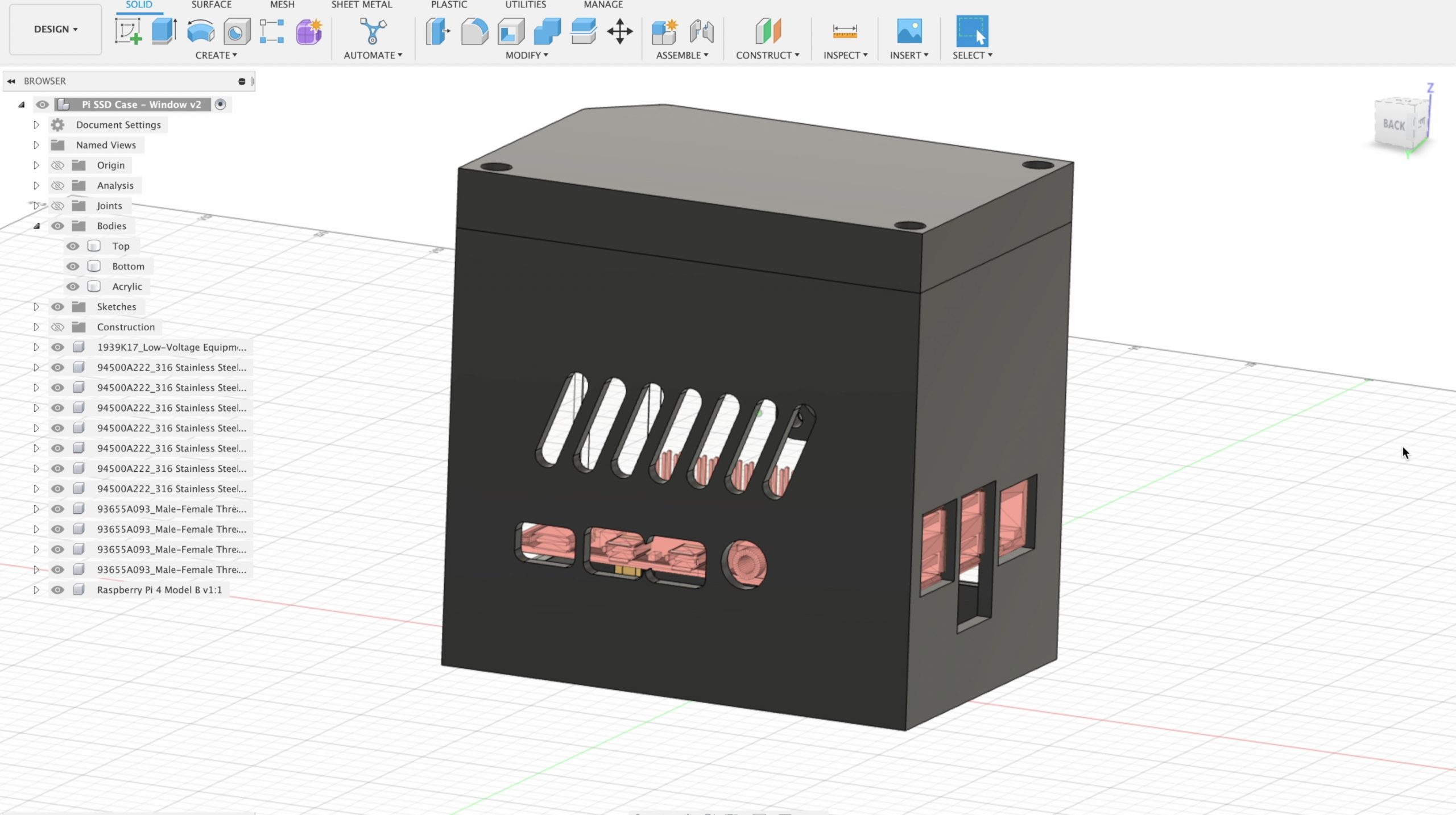
So I’ve got space for 6 fans on each side as well as 6 on the top, and space for 4 fans at the front and the back. We can’t have fans blocking the ports on the front of the Pi, so I’m going to get rid of the bottom two fans in that area and I’ll add some port cutouts into the design. So we’ll need a total of 24 fans for this design.
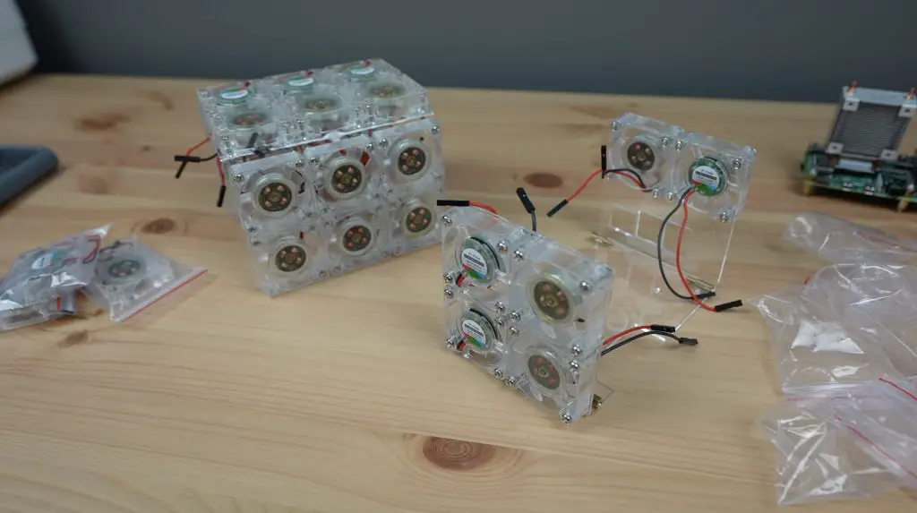
A not-so-quick Aliexpress order and two weeks later these arrived.

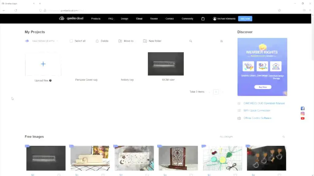
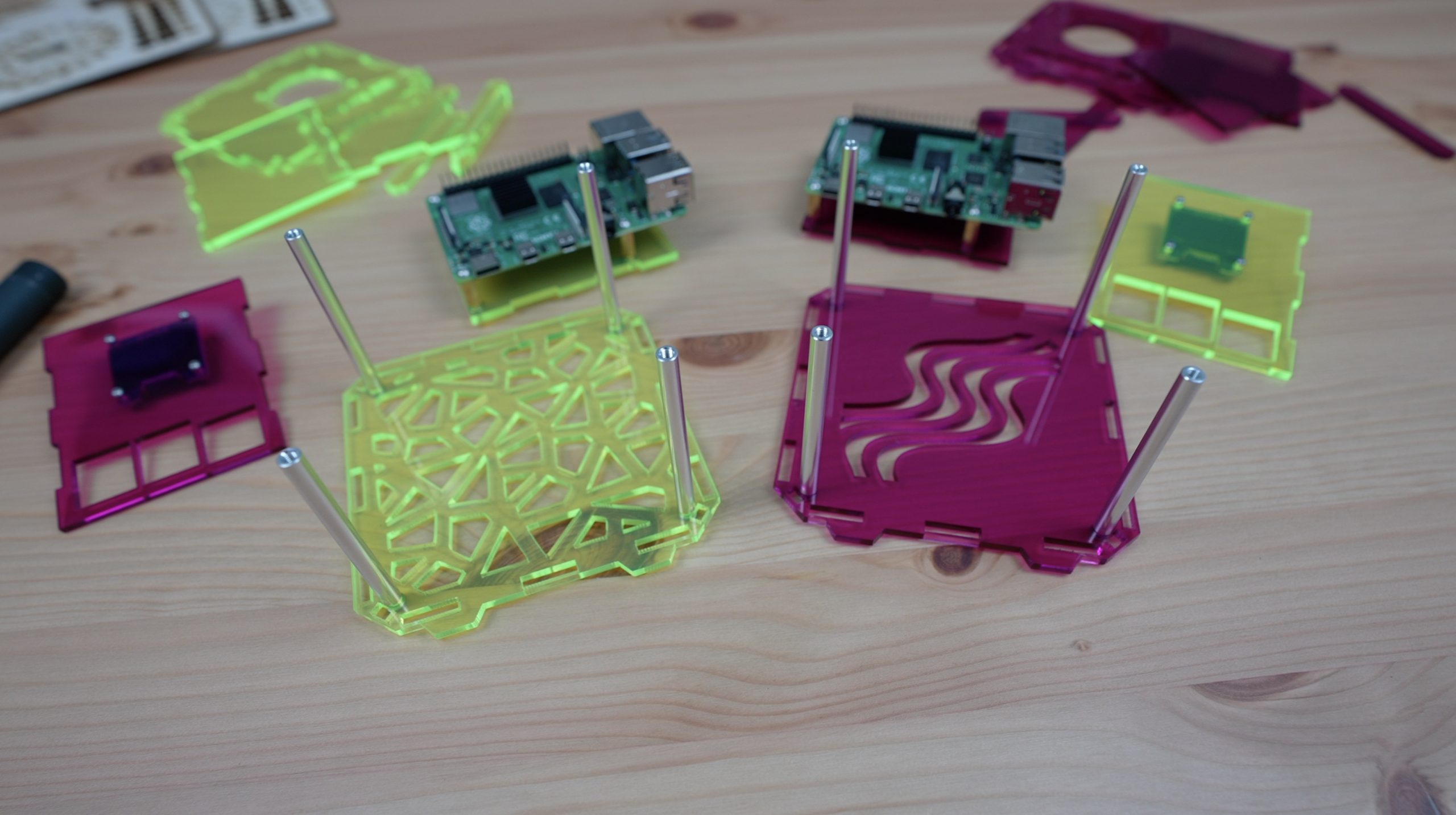
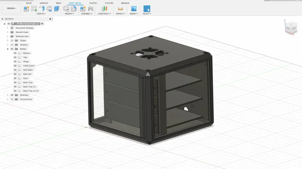
Now I could just glue them all together but that’s going to be a challenge at the corners and is going to make mounting the Pi difficult, so we need some sort of frame to hold the fans in place. The easiest way to make up this frame is going to be with some 2mm clear acrylic that I can laser cut.
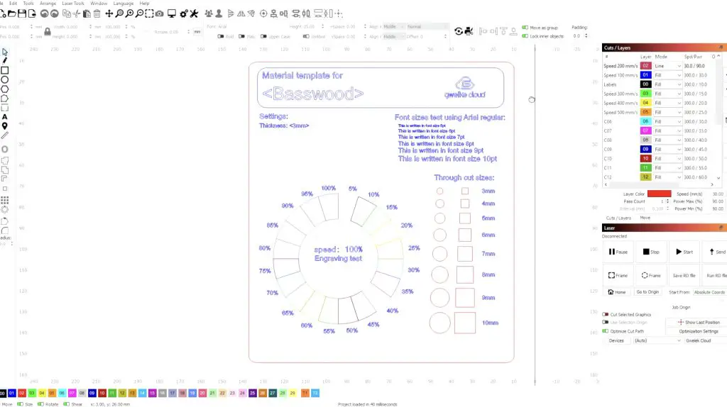
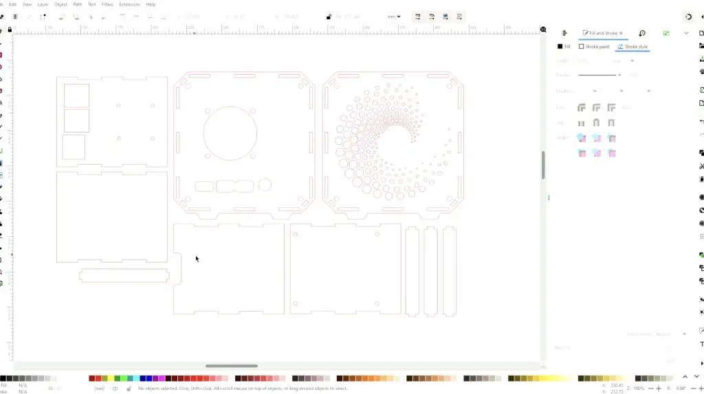
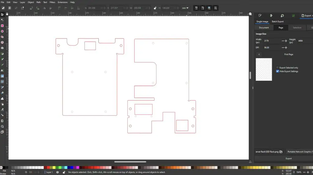
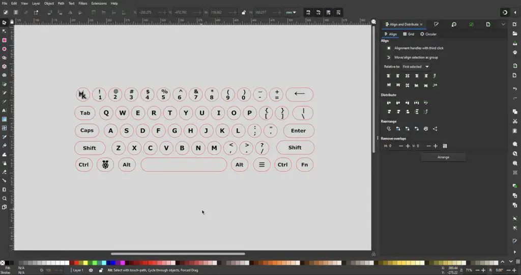
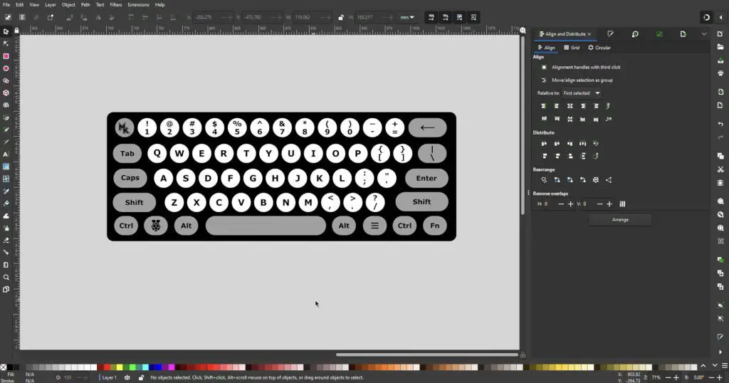
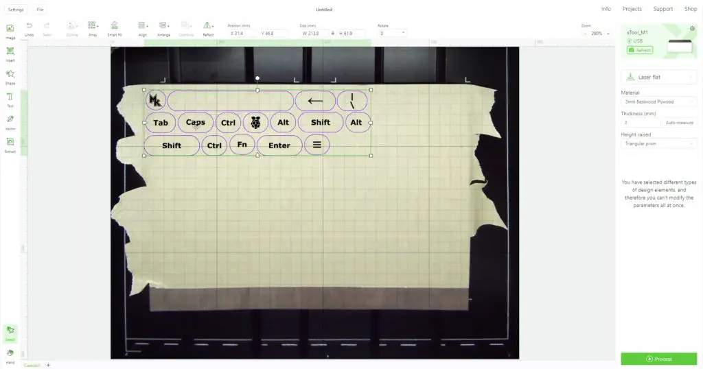
I drew up the design below in Inkscape.
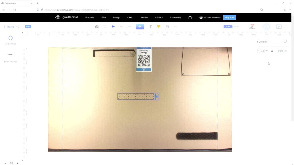
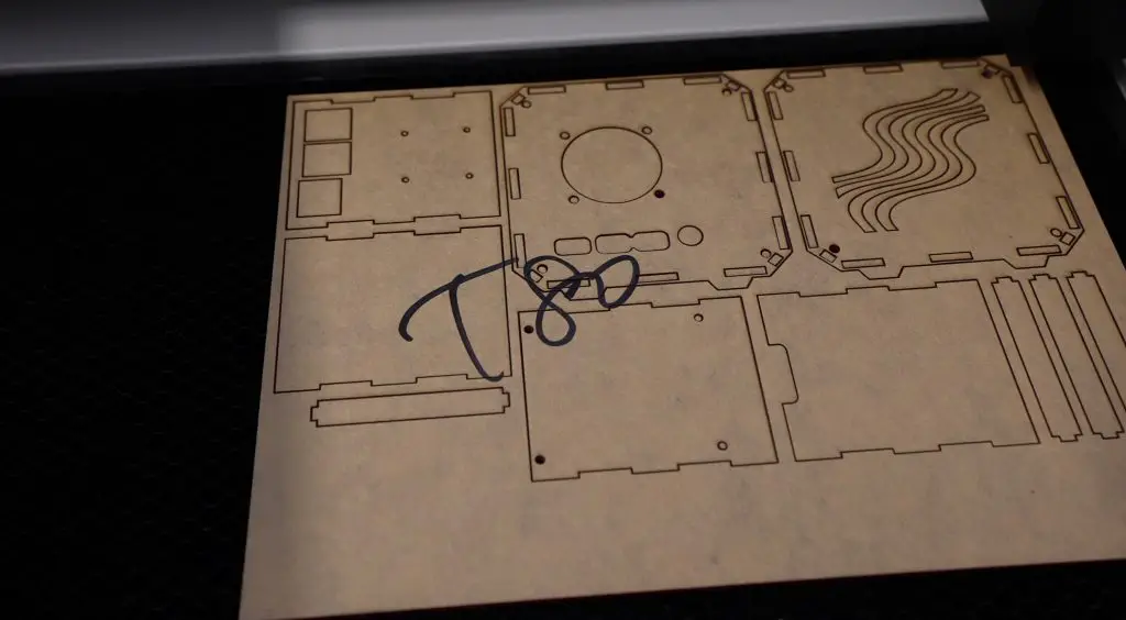
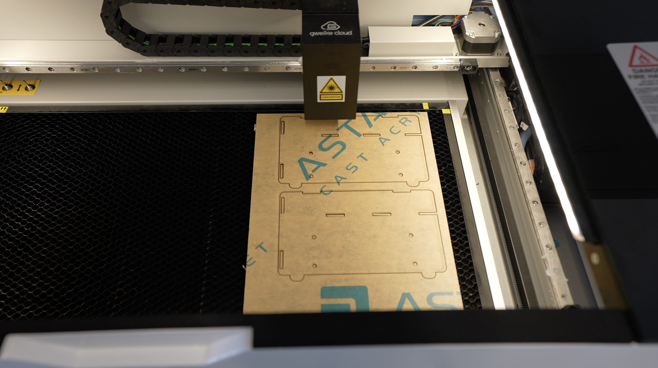
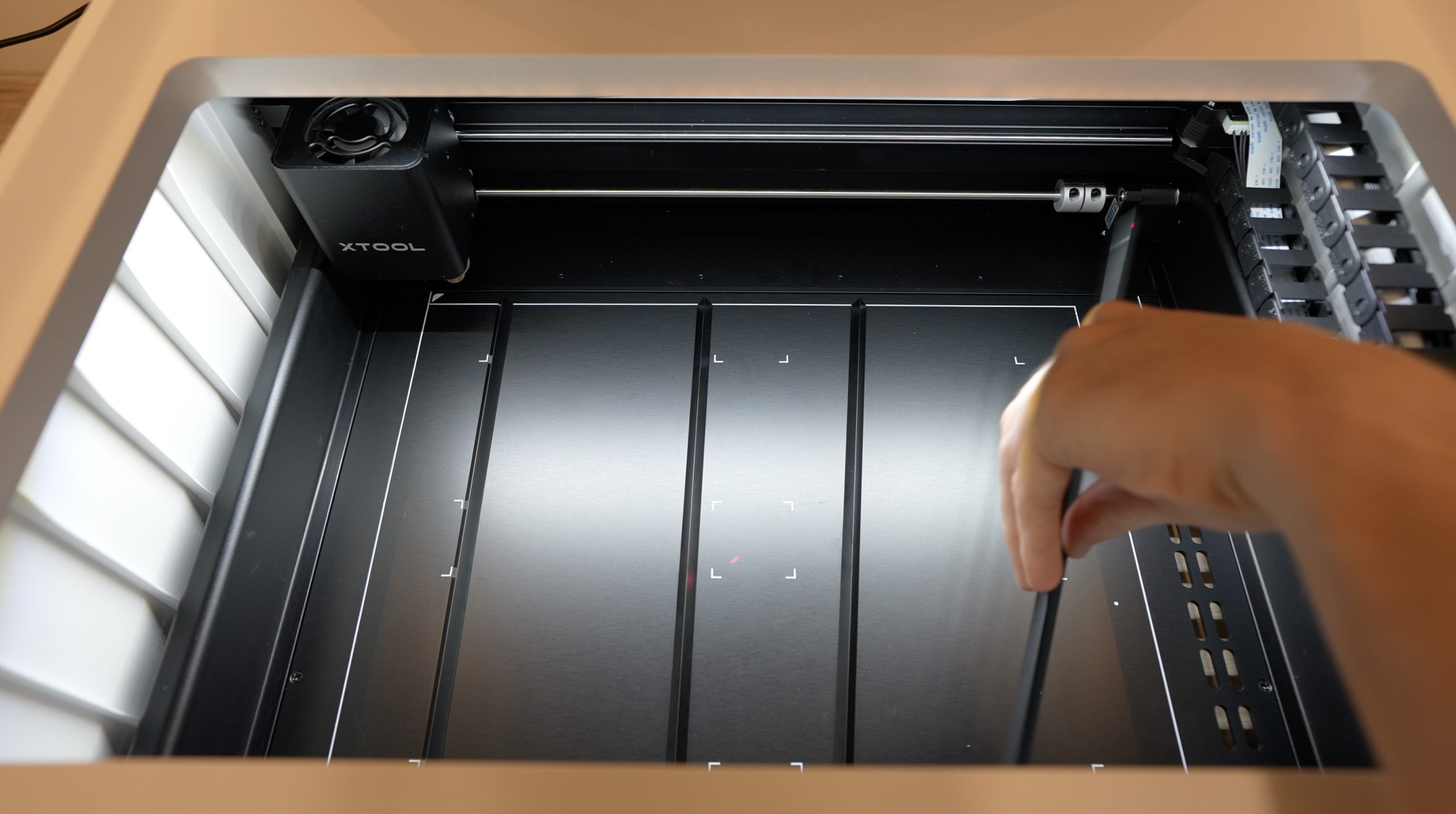
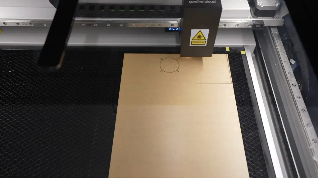
Laser Cutting Design
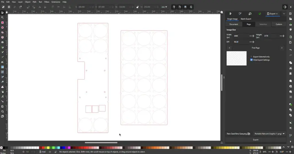
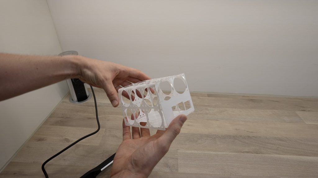
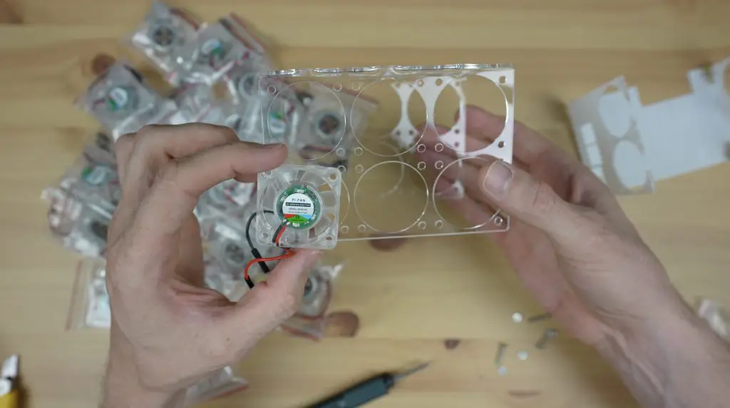
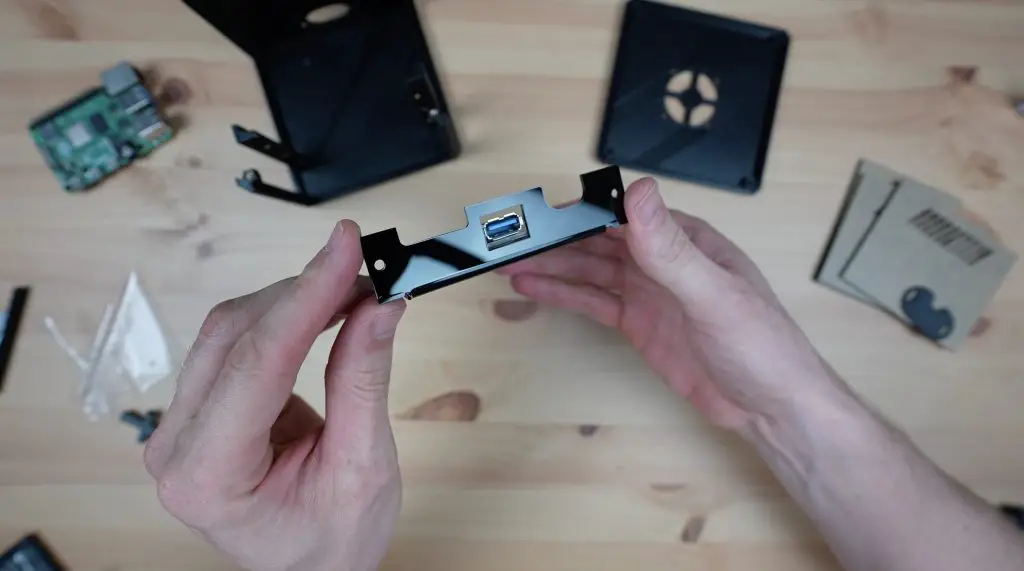
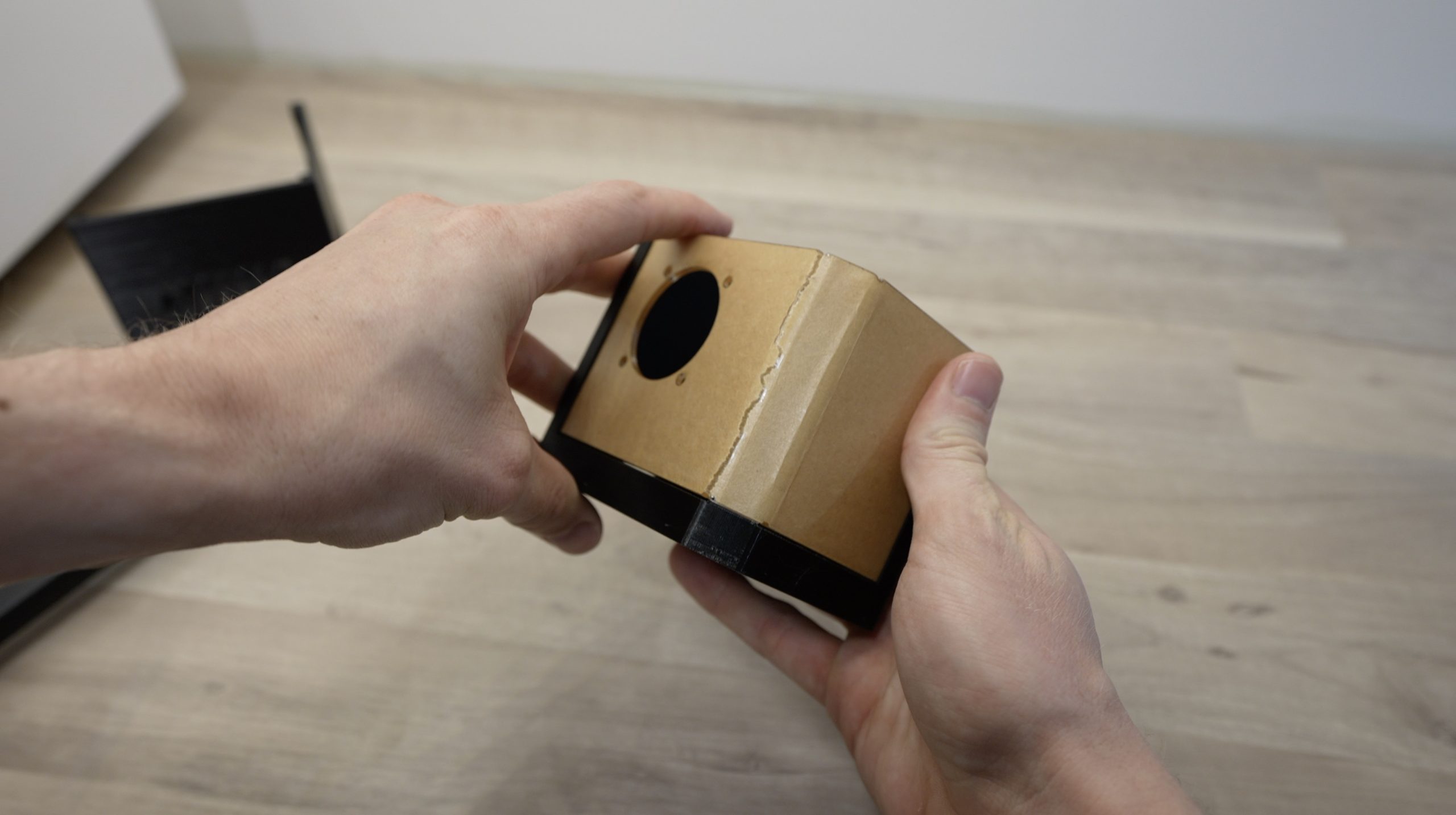
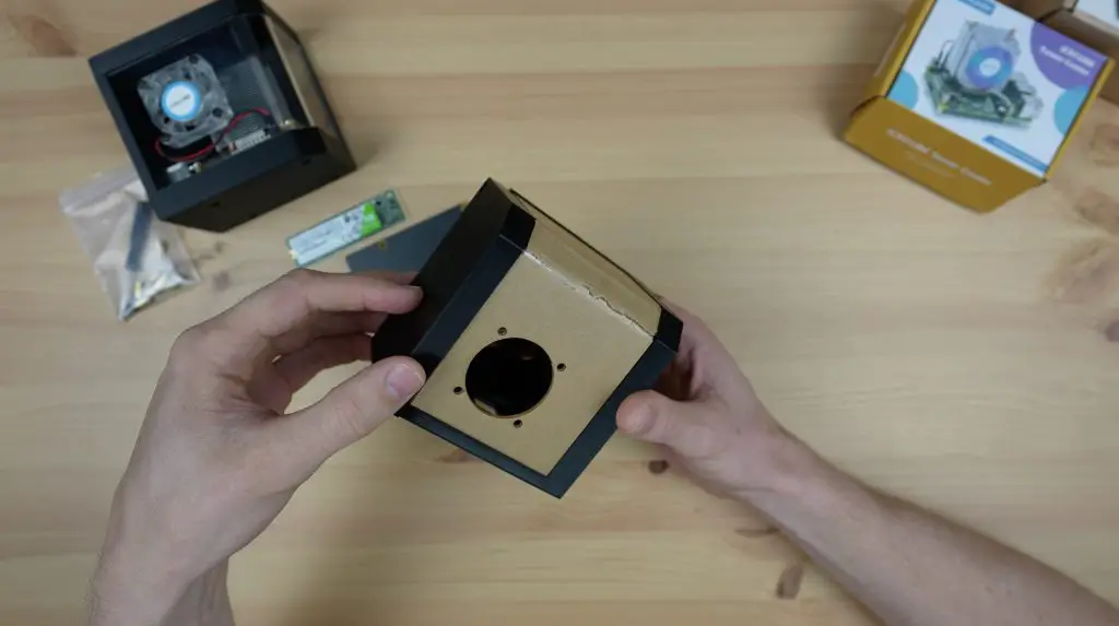
The design doesn’t add any restrictions to the fan’s airflow, it is there purely to hold the fans in place, so the hole for each fan is slightly larger than the fan diameter. It’s made up of two parts which will each be bent into a U shape to fit together and I’ll then need some 90-degree brackets in the corners to hold the two pieces together.
Making Up The Fan Case Components
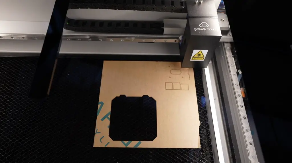
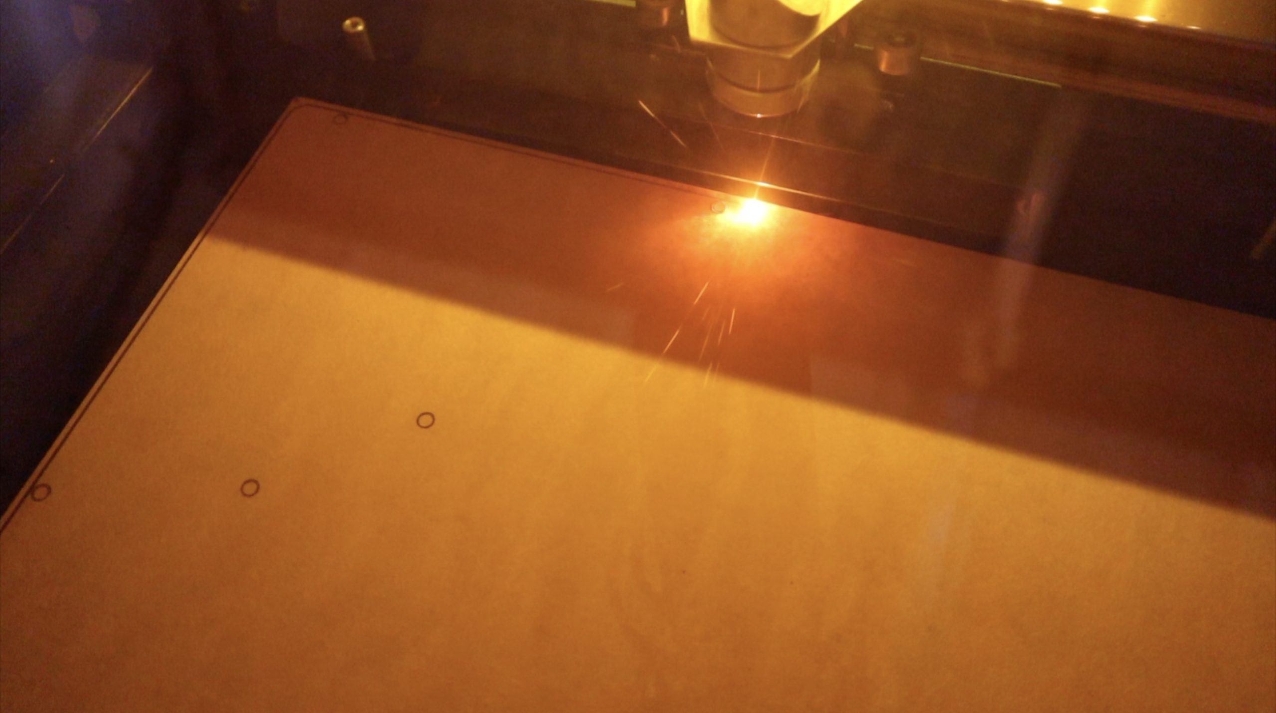
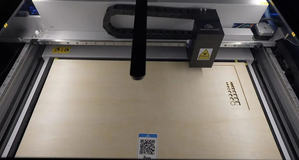
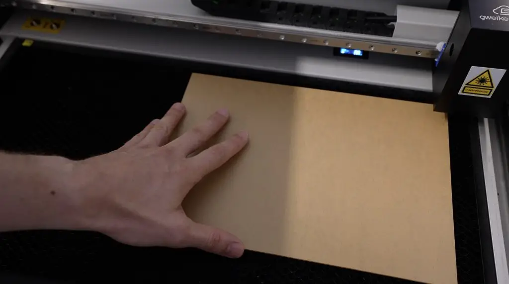
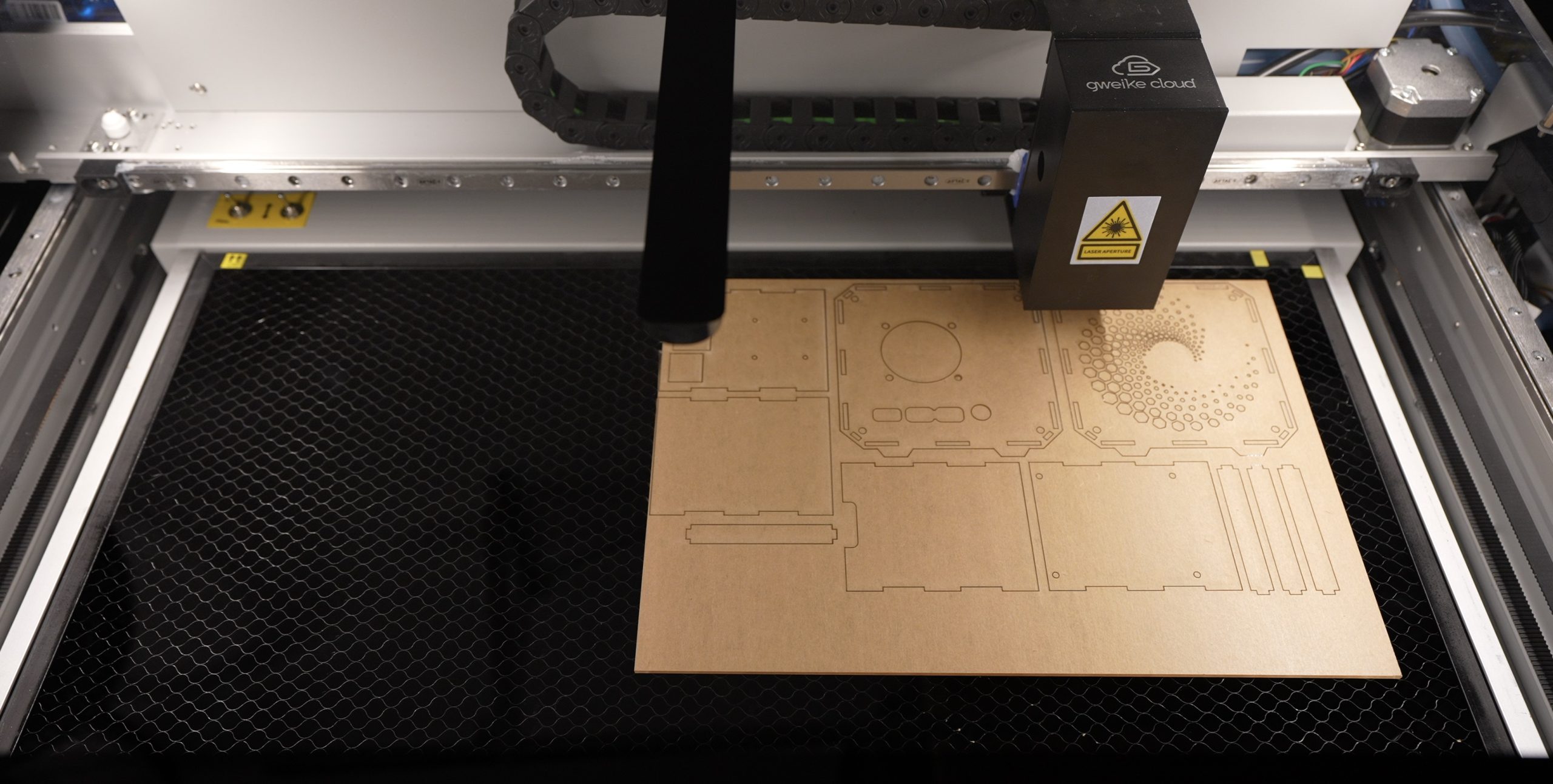
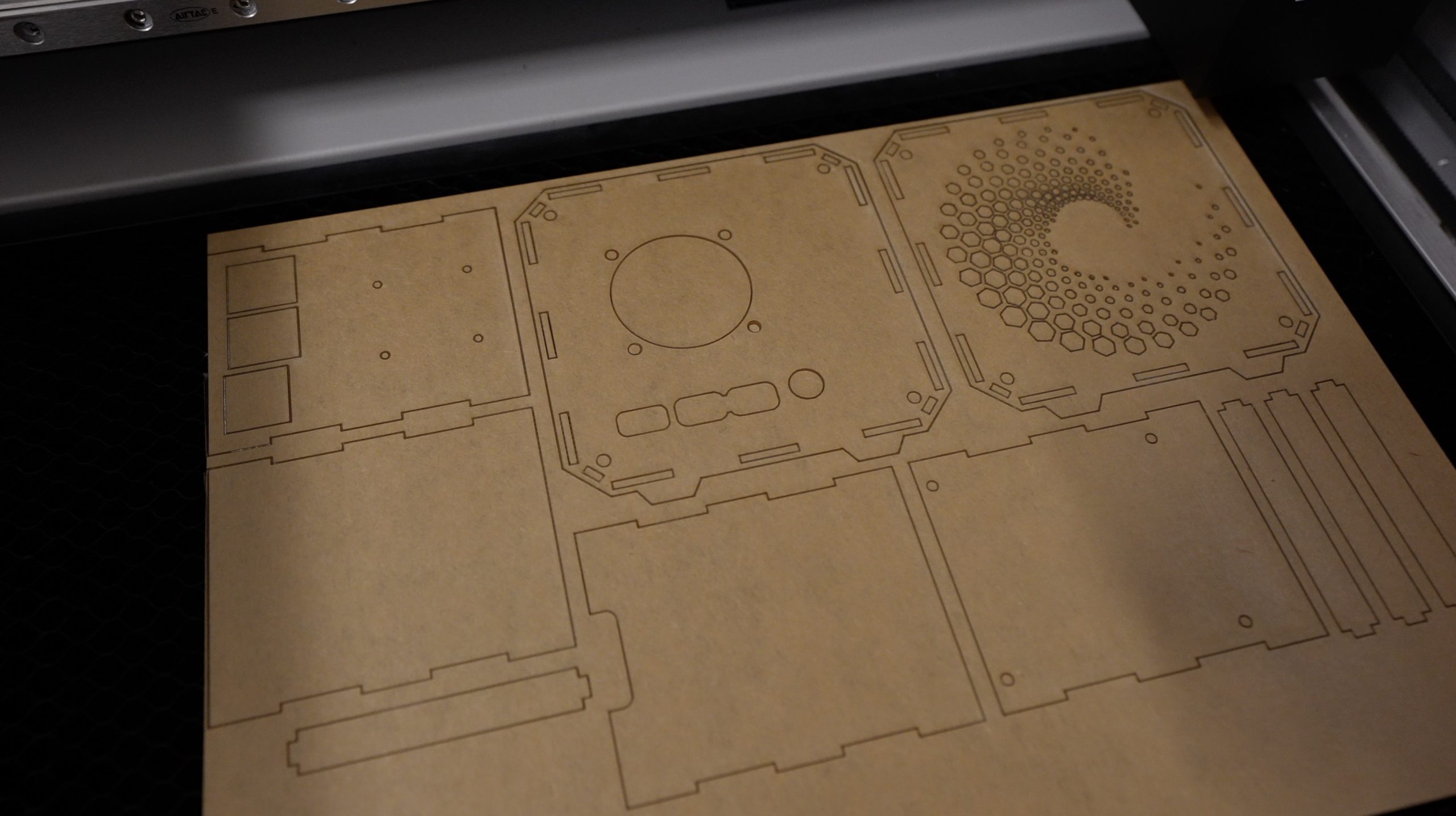
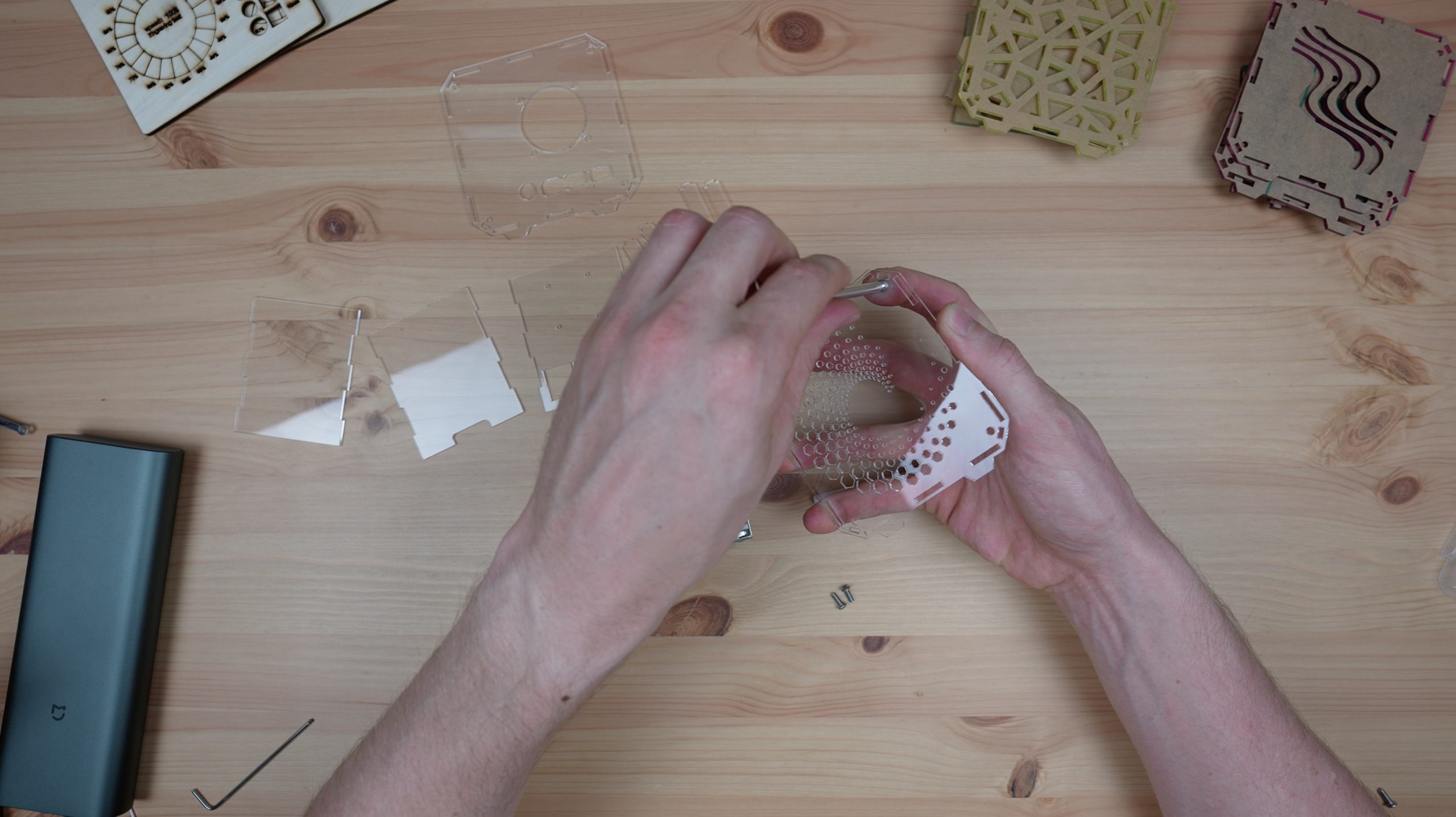
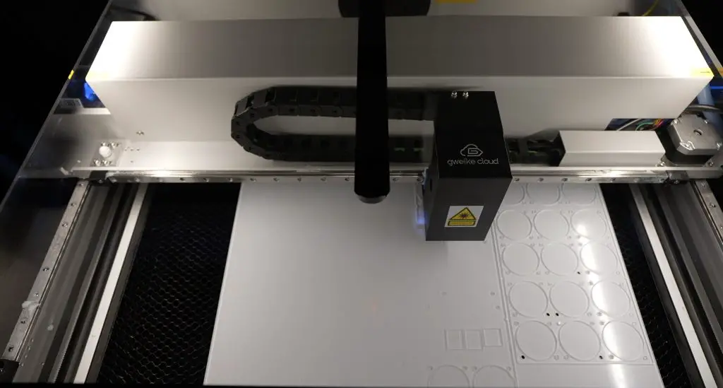
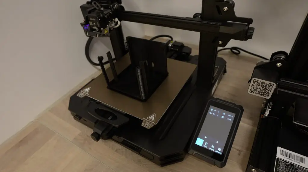
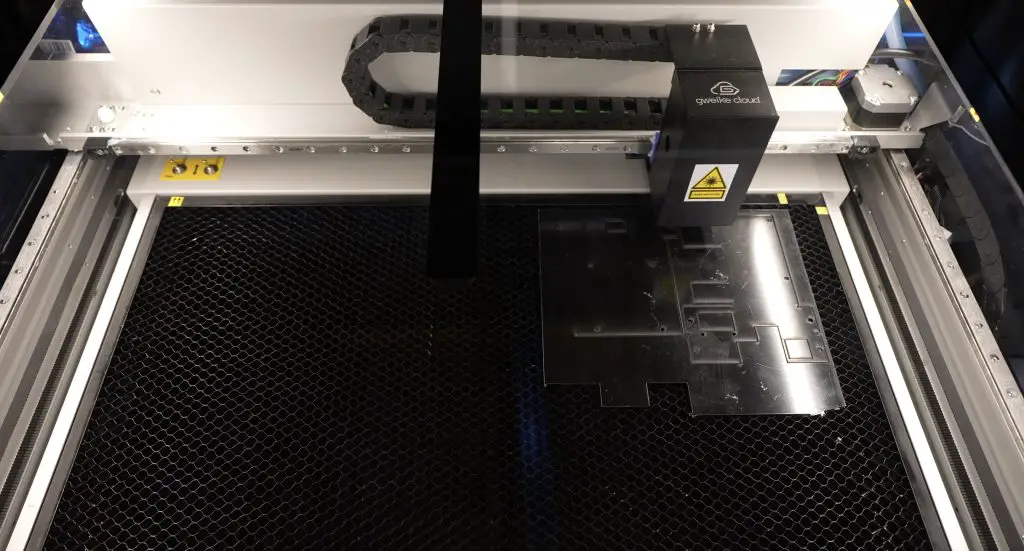
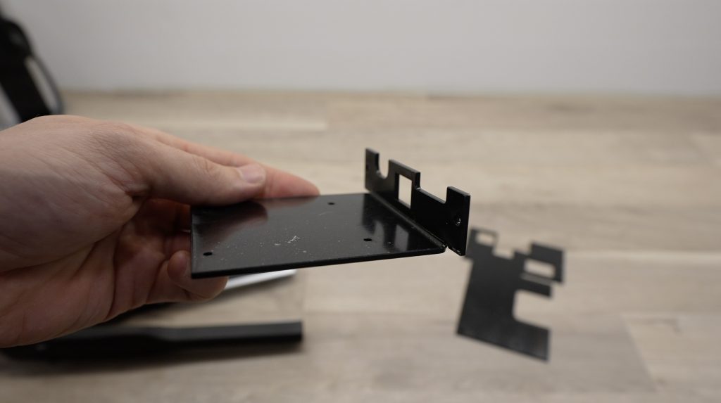
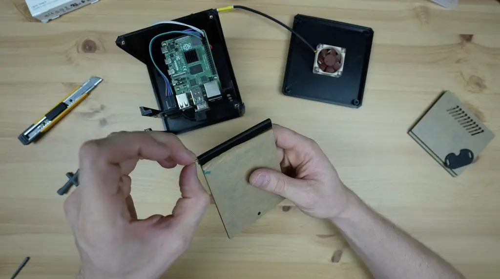
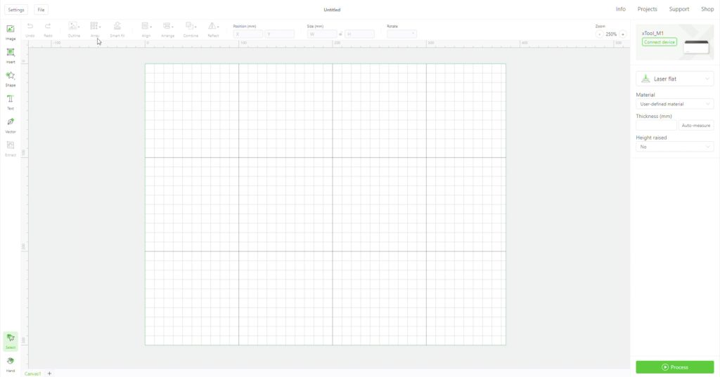
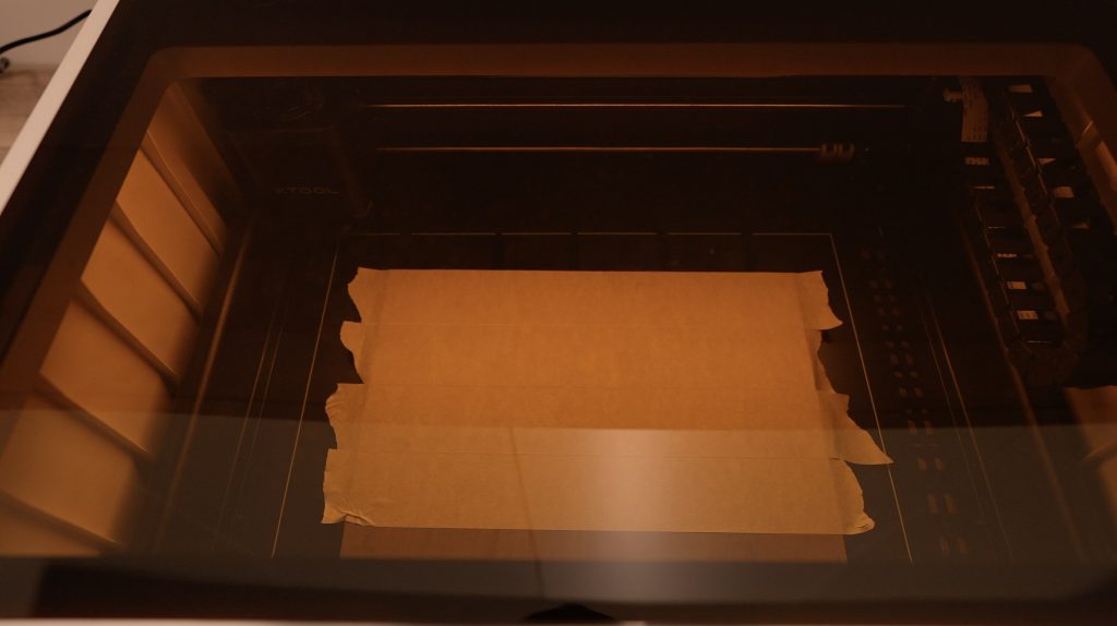
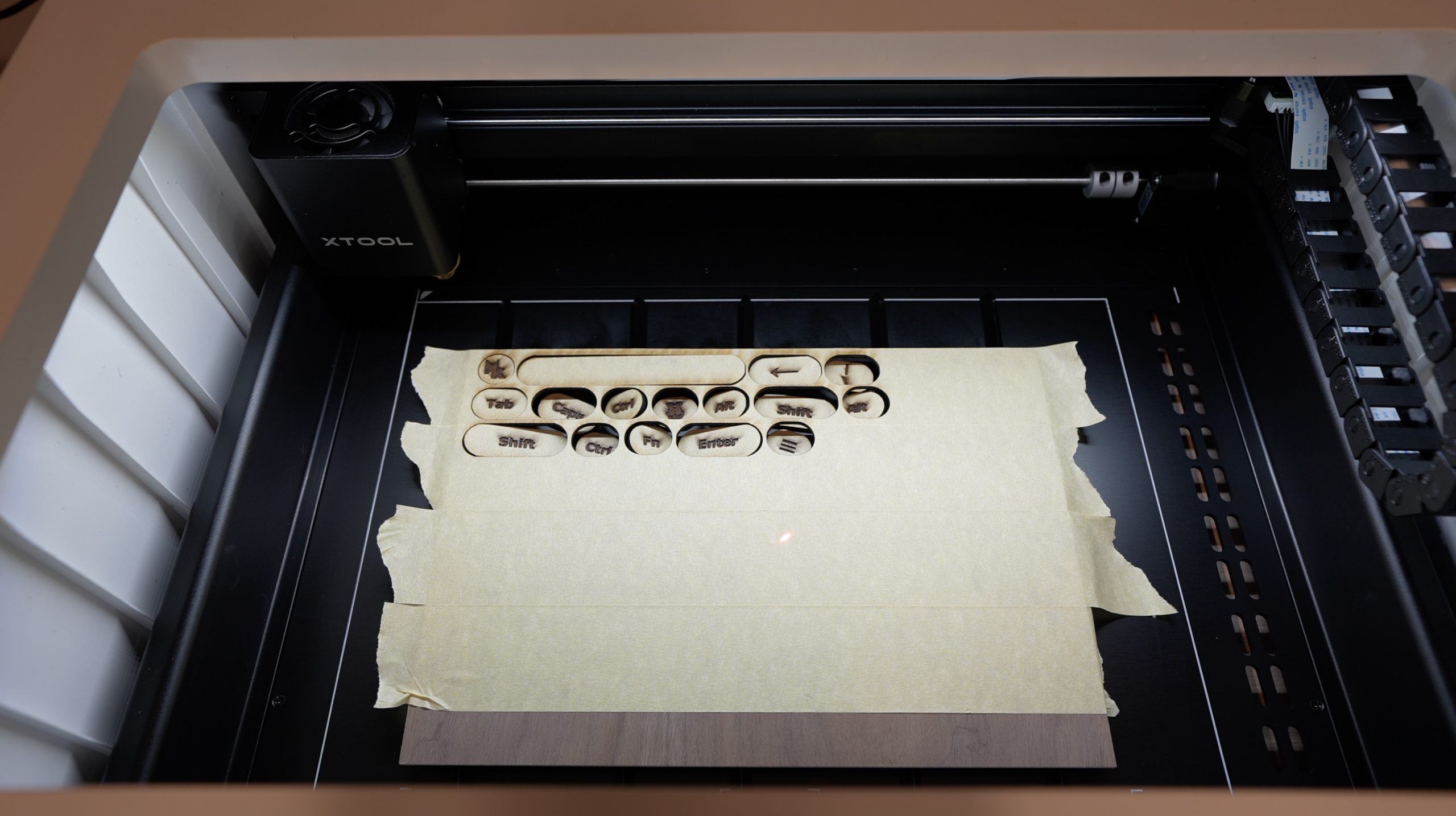
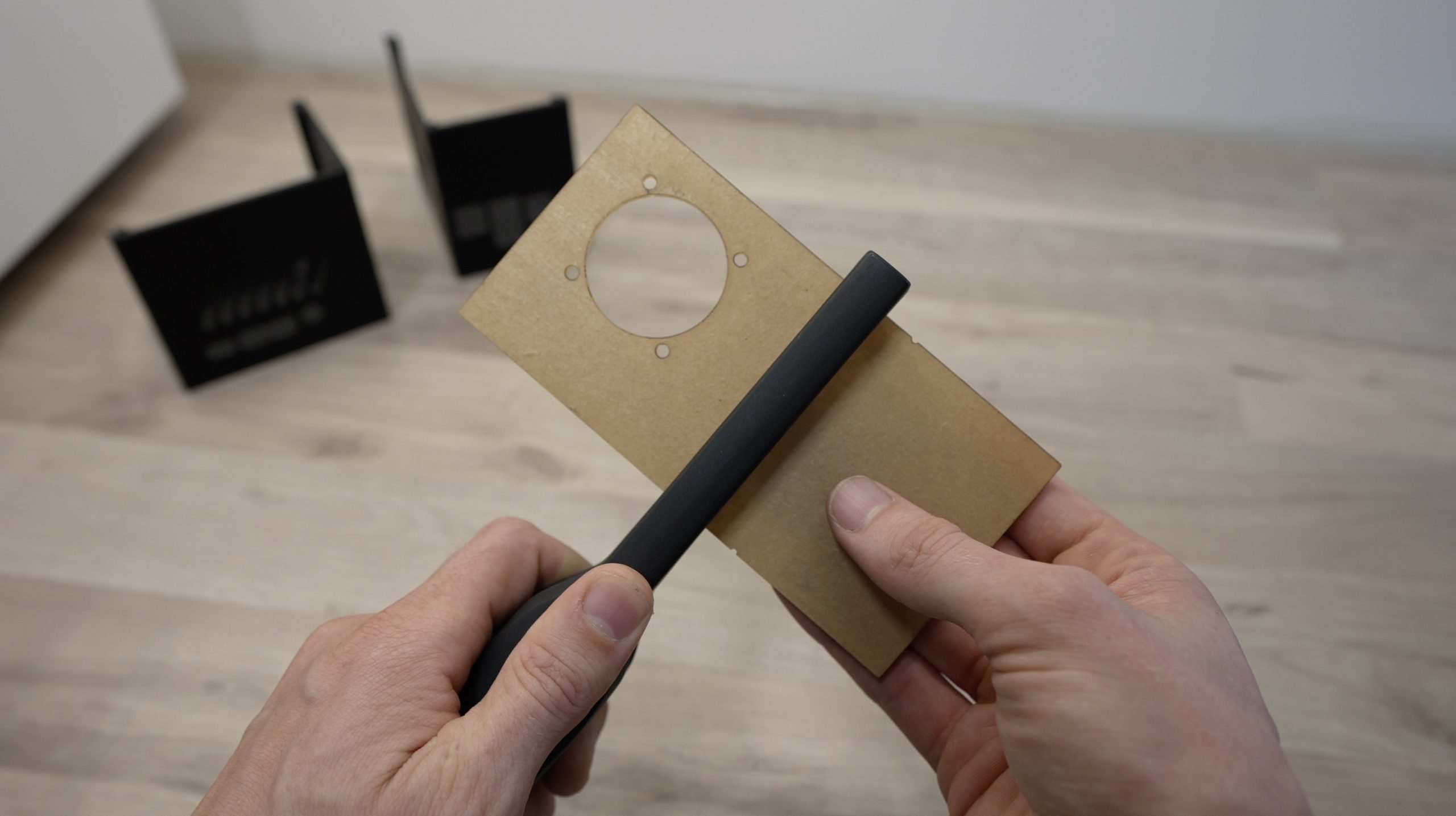
I laser cut the two parts from a single sheet of 2mm clear acrylic.
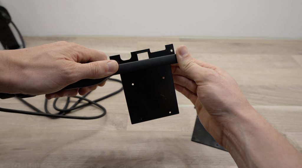
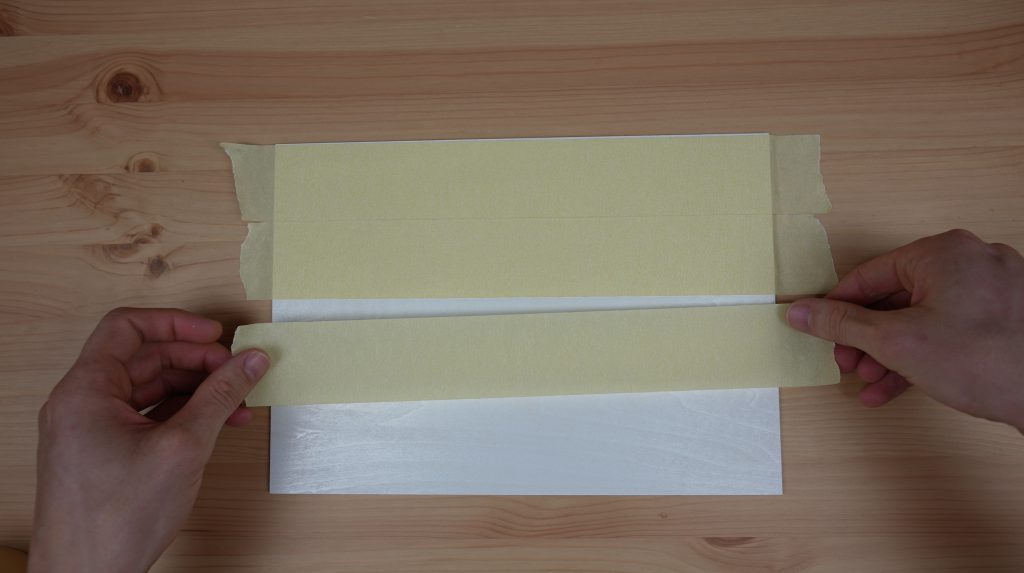
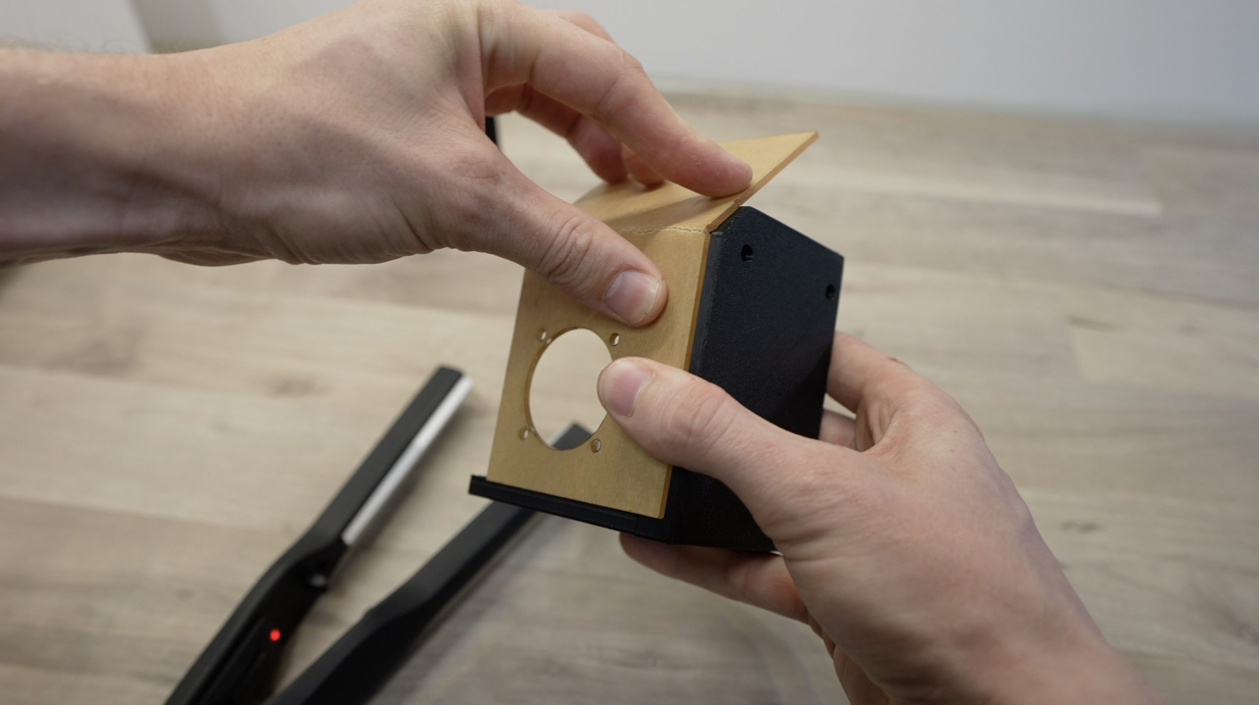
I then bent the parts using an acrylic bending tool to heat up a line between the notches cut into the sides and I used a wide 90-degree bracket to make sure that the bends came out square.
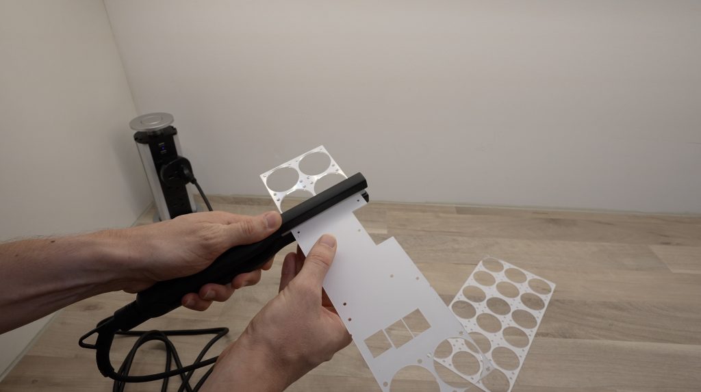
Both of these turned out to be a bit more difficult than I had hoped. I bent the sides on the first piece the wrong way around and had to go back and reheat them to bend them the other way. The second piece was longer than the element on the bending tool so I had to reheat it from both sides a couple of times before it was hot enough to actually make the bend. But I eventually got the two parts made up correctly in the end.
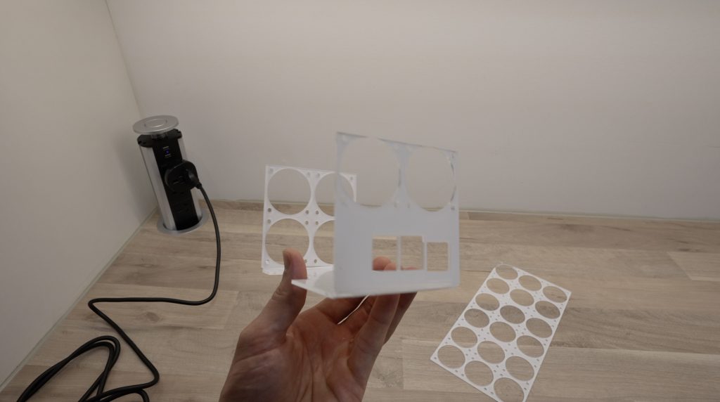
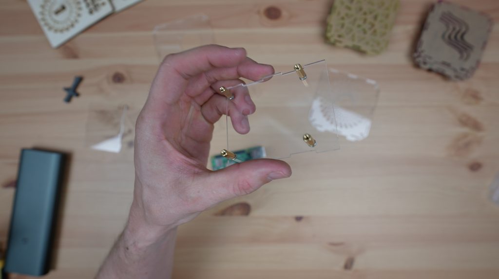
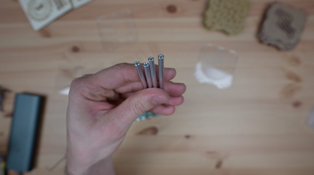
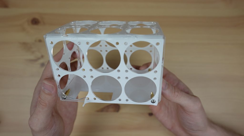
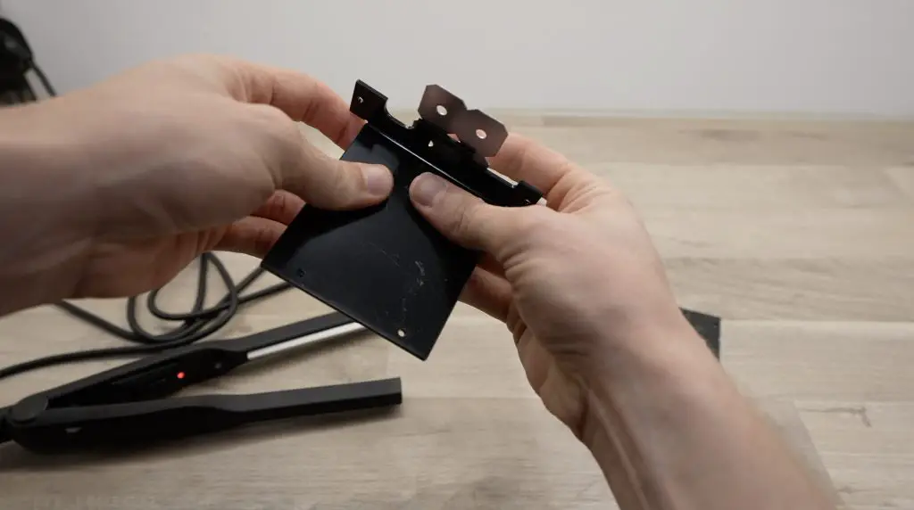
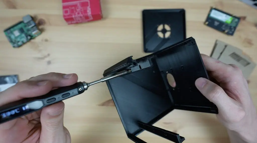
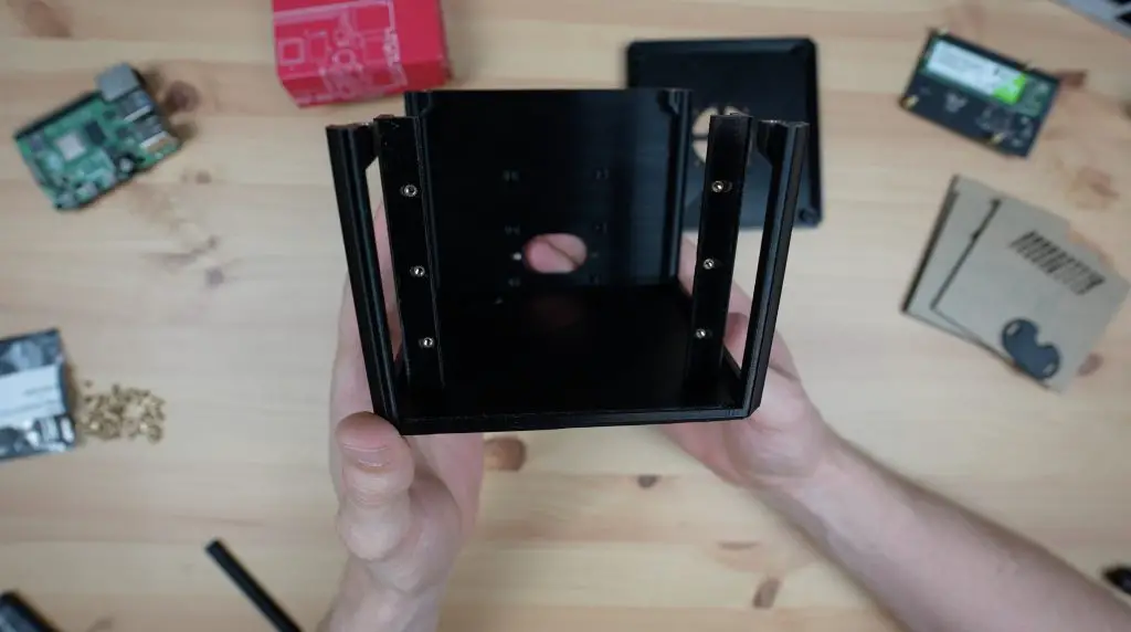
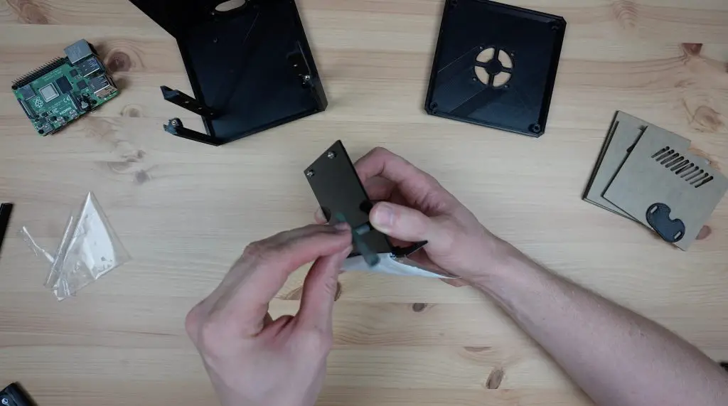
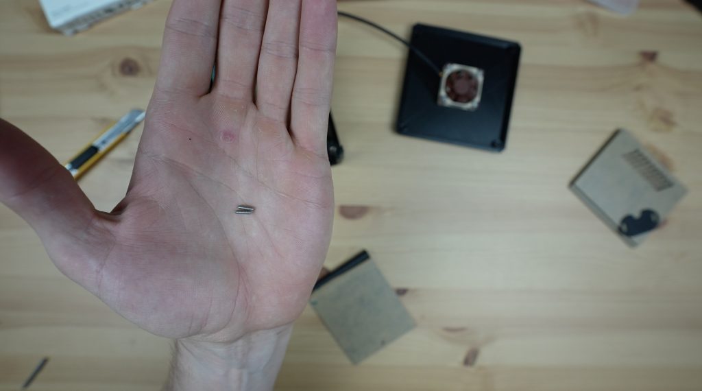
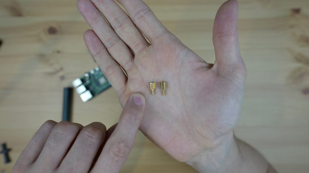
Now that I’ve got the parts in my hands, I actually think it’s going to be easier to hold together if I glue some brass inserts onto the base for the sides of the top section to screw into, so I’m going to glue an M3x10mm standoff into each corner which aligns with the corner fan screws.
Mounting The Fans Onto The Case Frame
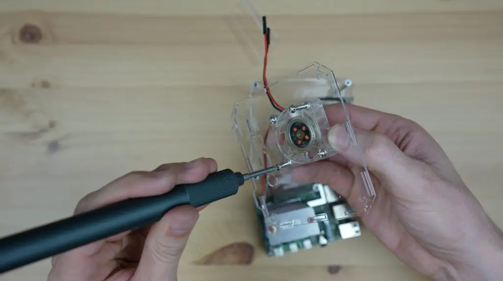
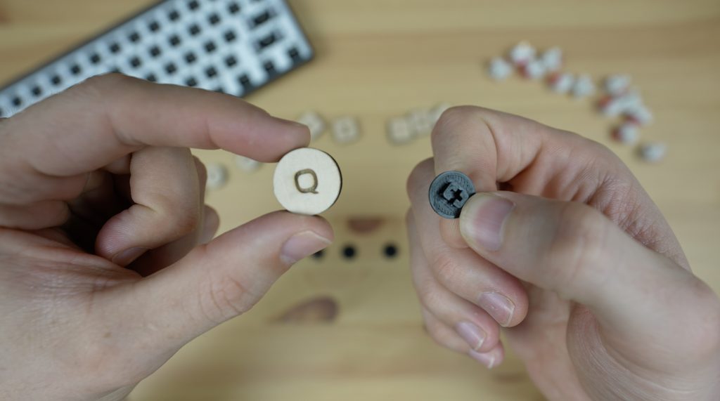
Next I need to get all 24 of these fans mounted onto the case frame. To do this, I’m using the four M3 button head screws and nuts that came with each fan.
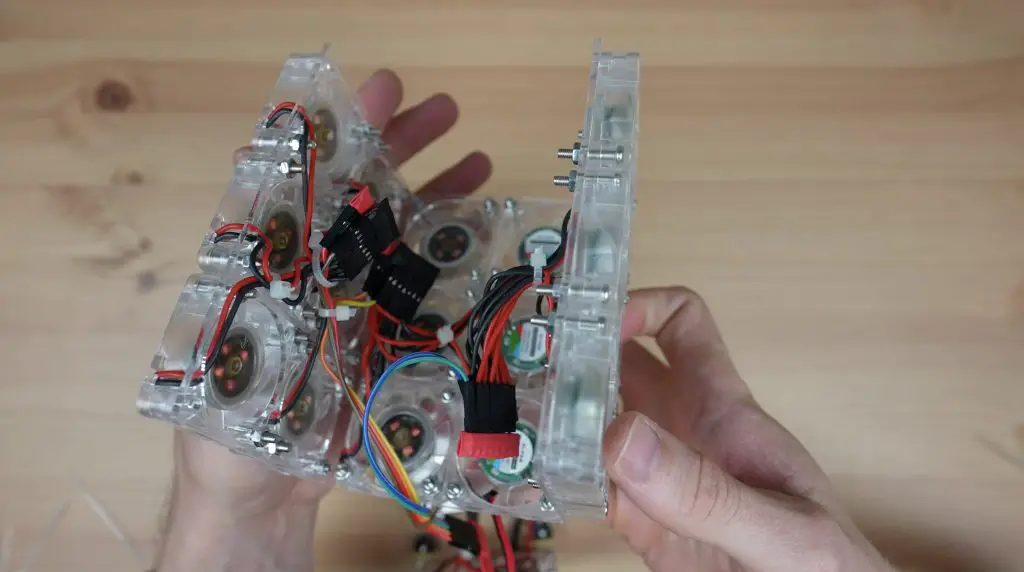
I realised at this stage that I hadn’t really decided which fans would be pushing air into the case and which would be pulling air out, so I decided that it would be best to have an even split and since people often complain about air dead spots in my case design I thought it would be best to have all of the fans on one side pushing air into the case and all of the fans on the other side pulling air out of the case. This is so that there are no fans opposing or competing with each other.
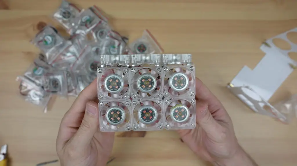
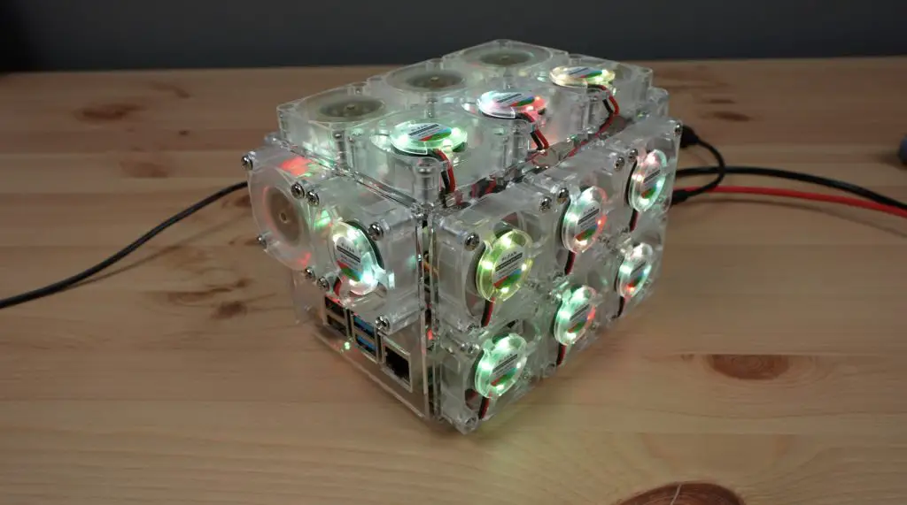
I then mounted all 24 fans onto the two case halves, with all of the fans on the left blowing air into the case and all of the fans on the right pulling air out of the case.
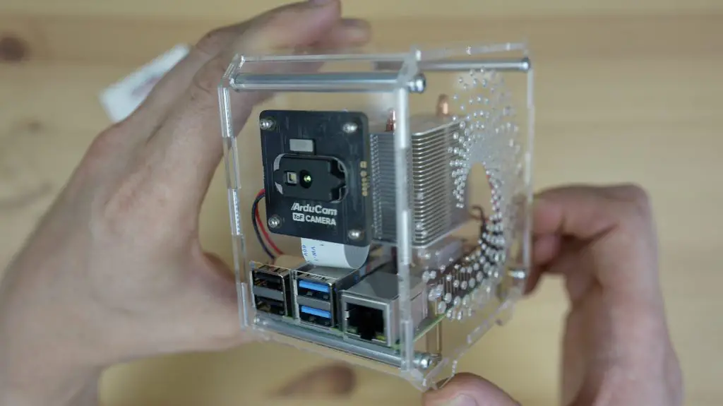
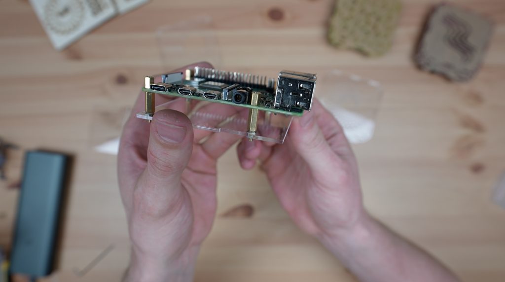
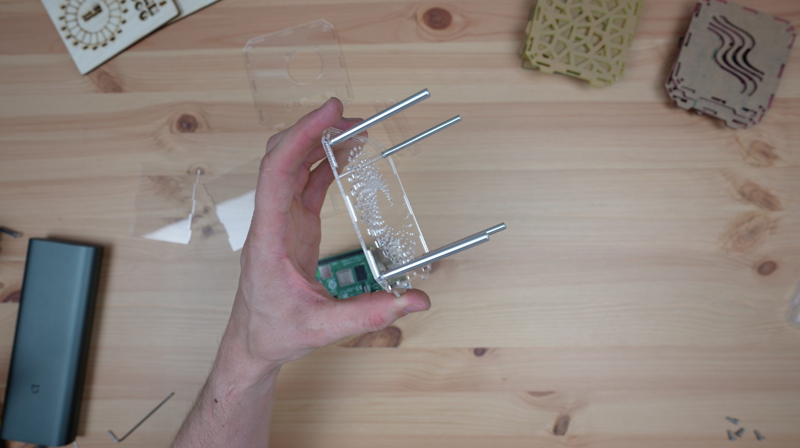
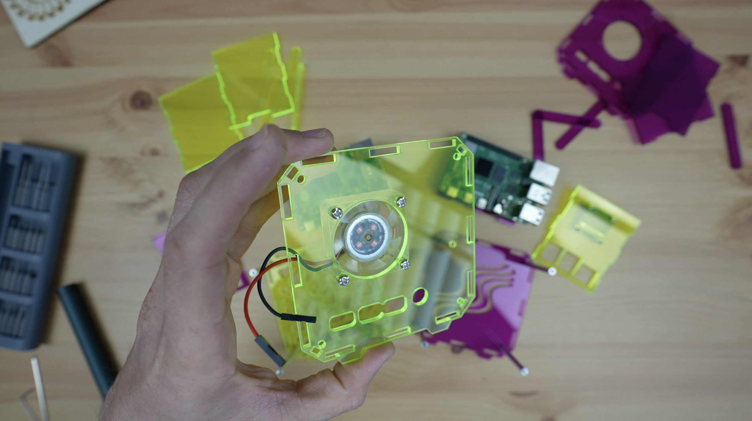
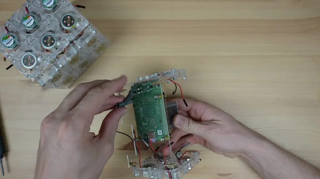
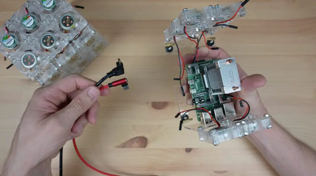
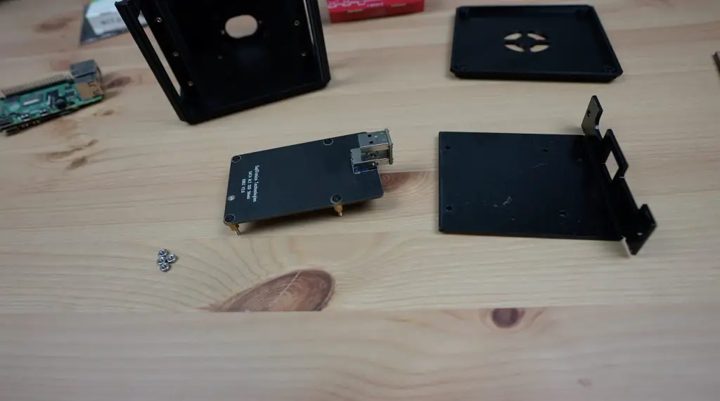
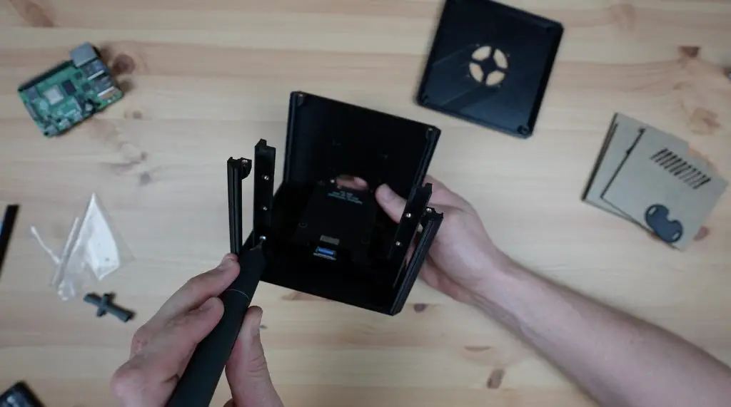
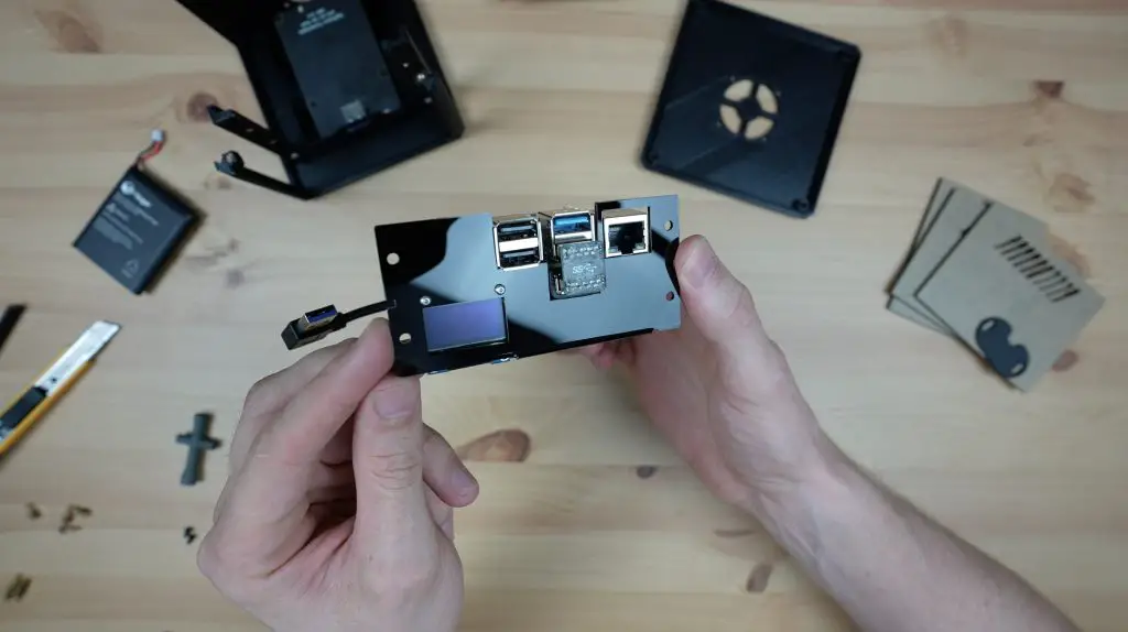
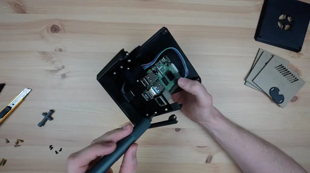
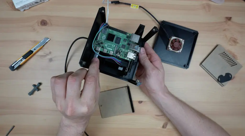
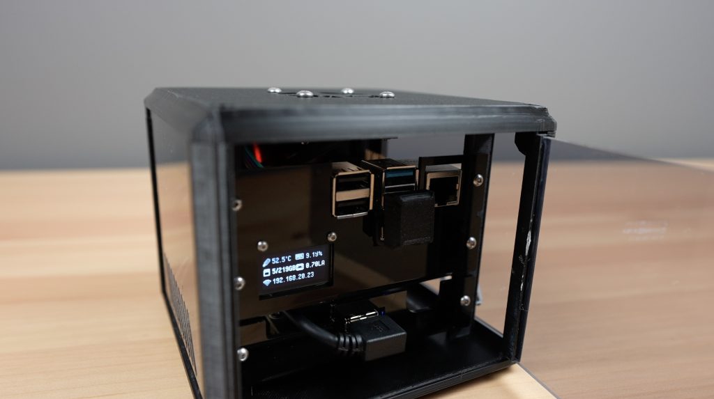
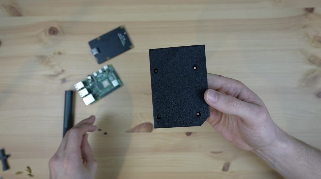
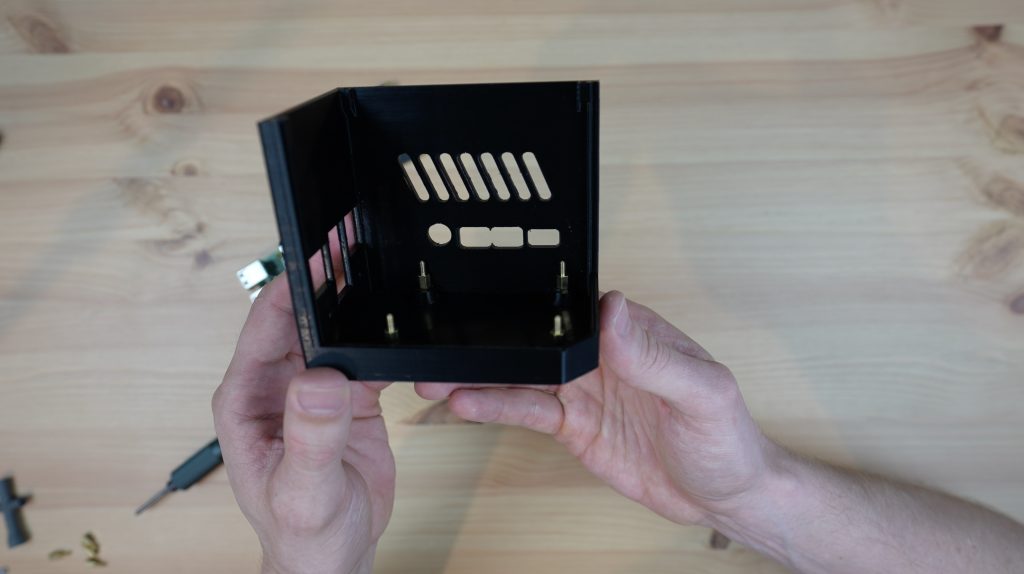
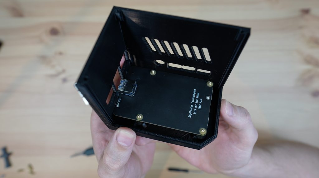
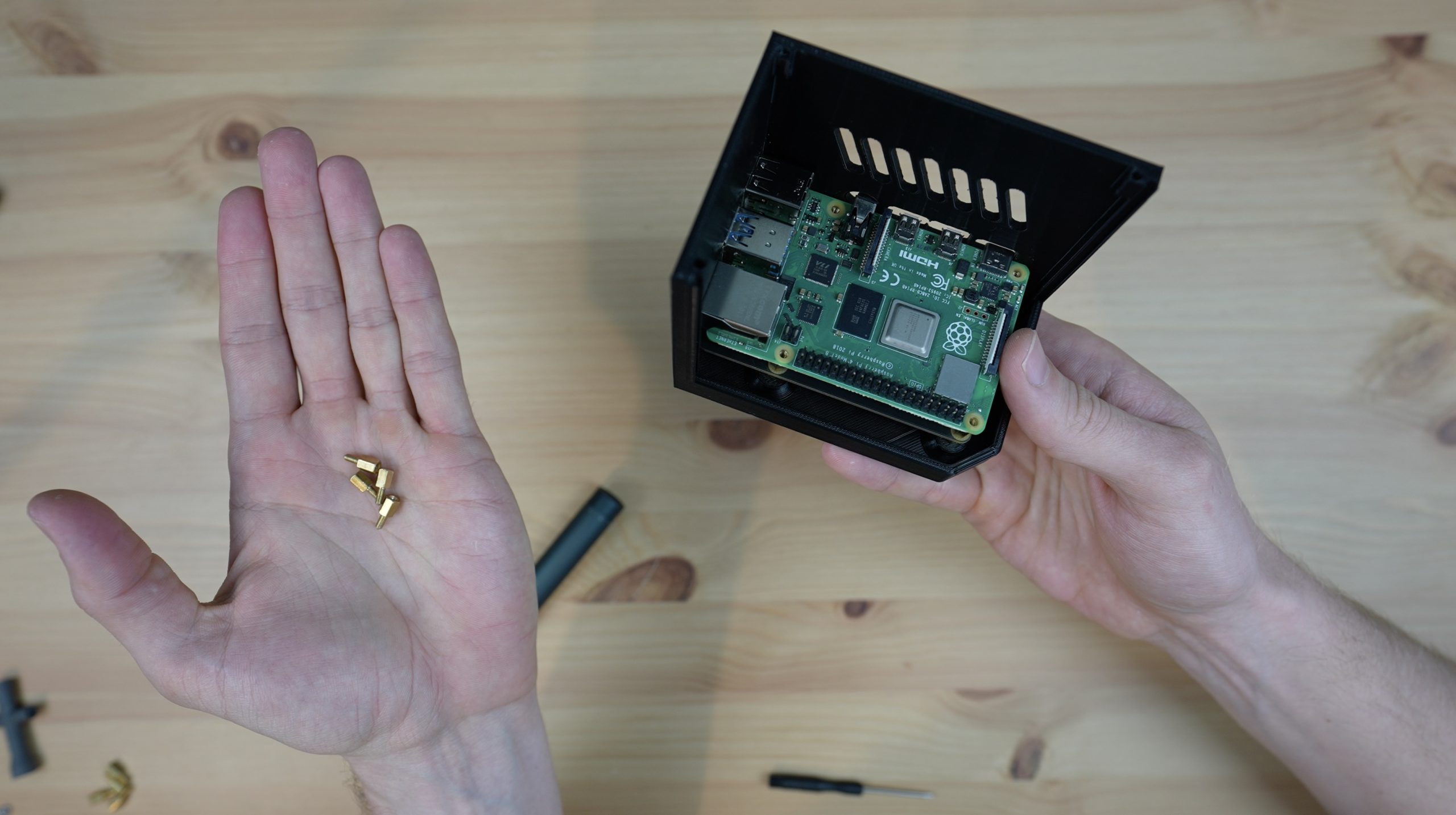
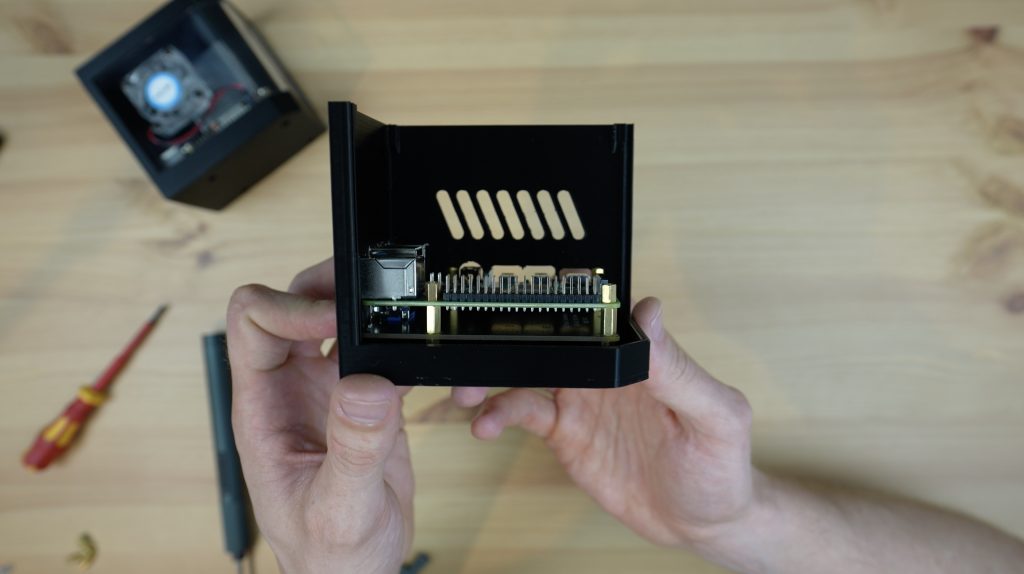
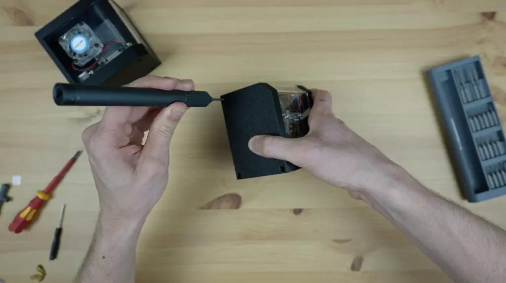
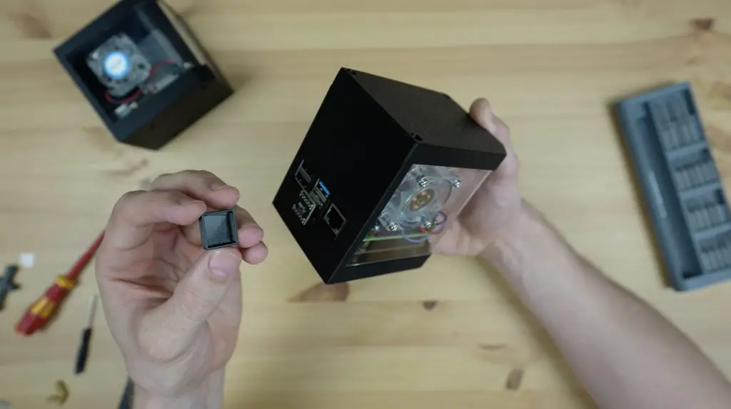
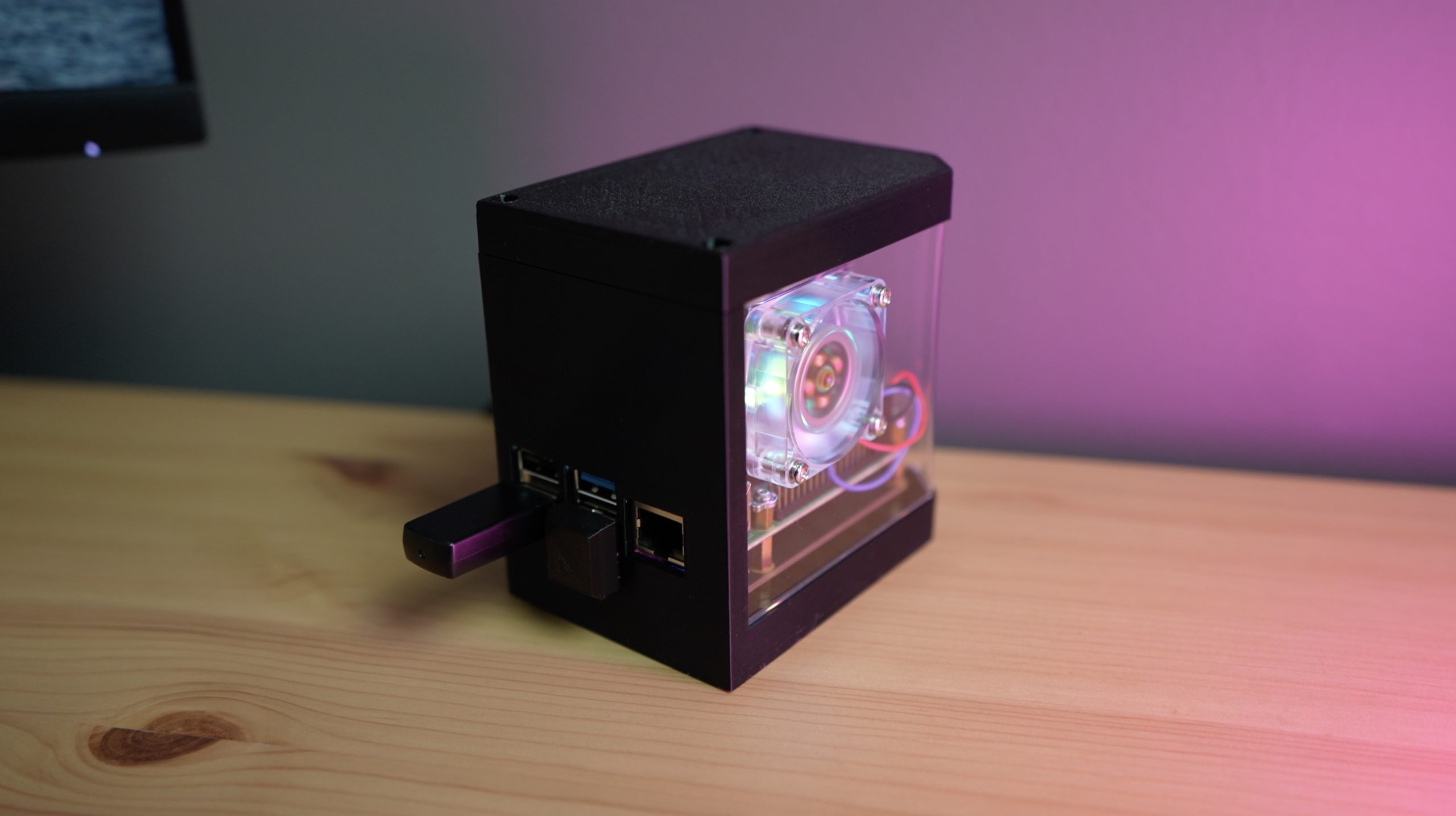
With the fans all done, we can mount the Raspberry Pi and Ice Tower assembly into the case. With the bend in the acrylic, the ports are slightly too high so I’ve added a nut as a spacer onto the bottom of each stand-off so that the Pi sits a little higher.
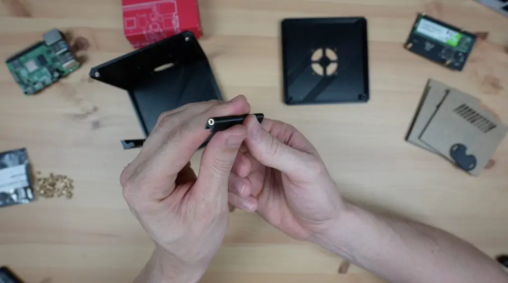
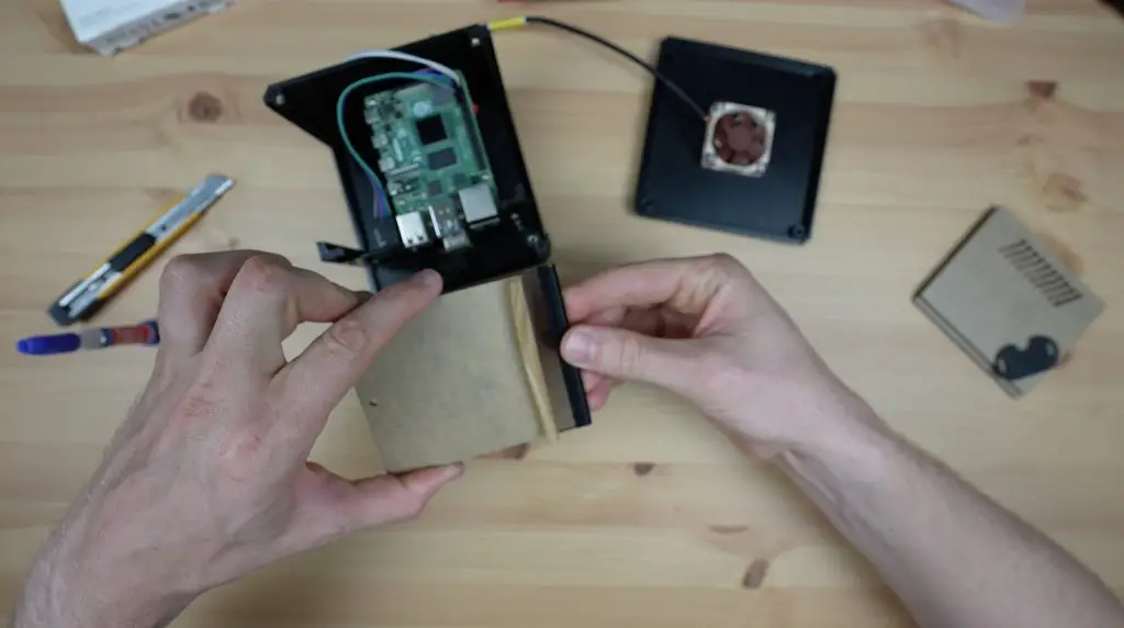
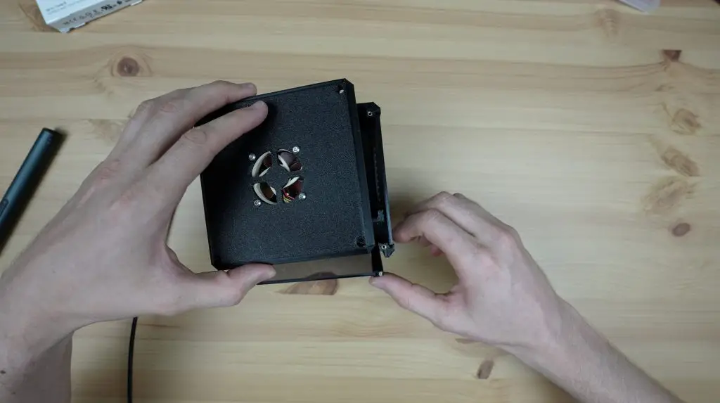
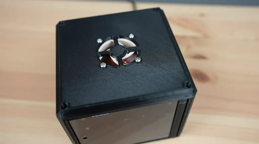
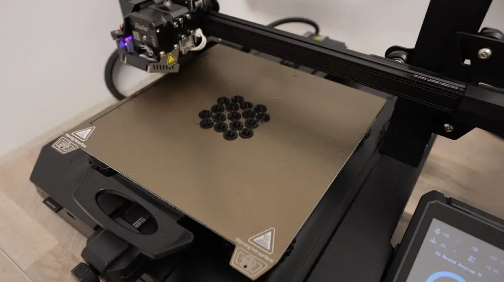
I’m also adding a small rubber foot on each of the four corners of the base so that it doesn’t vibrate itself around my desk.
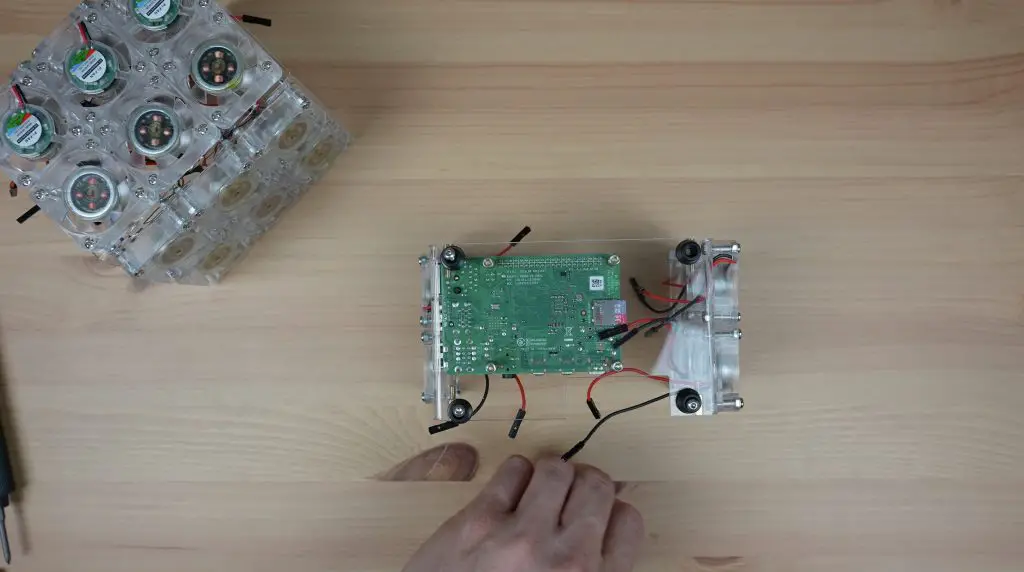
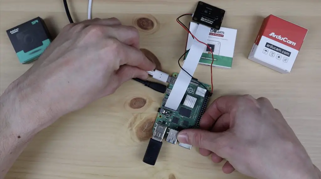
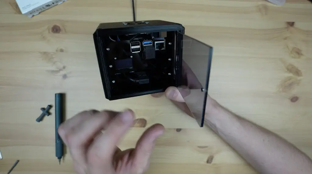
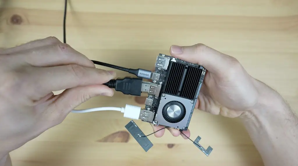
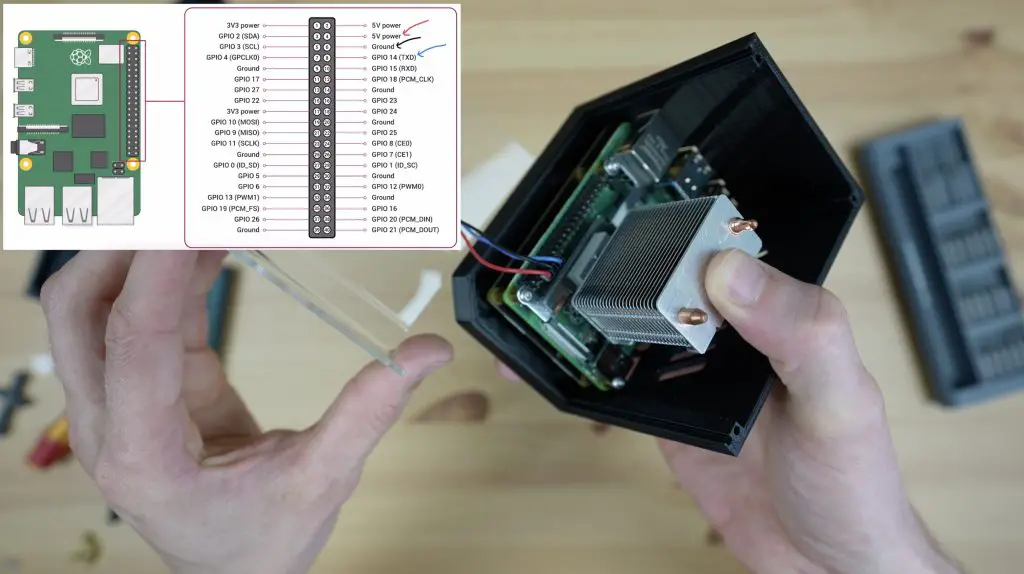
I’ve got some 90-degree cables for power and HDMI so that these can run through the base.
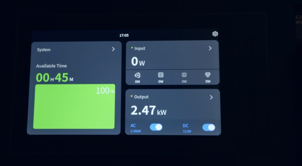
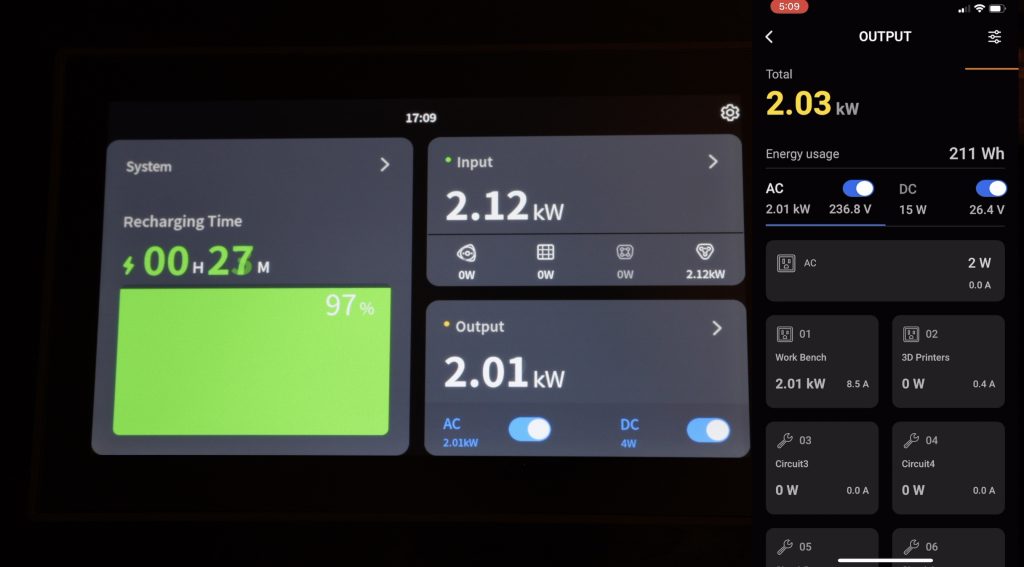
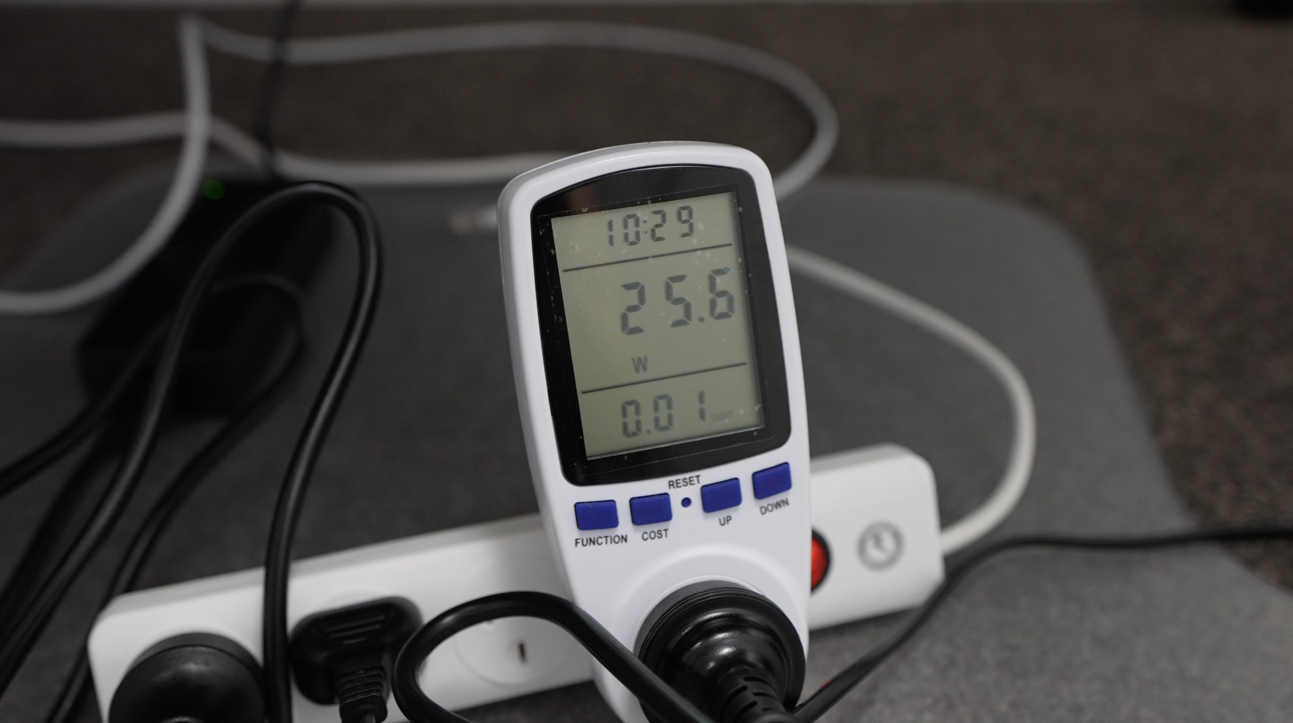
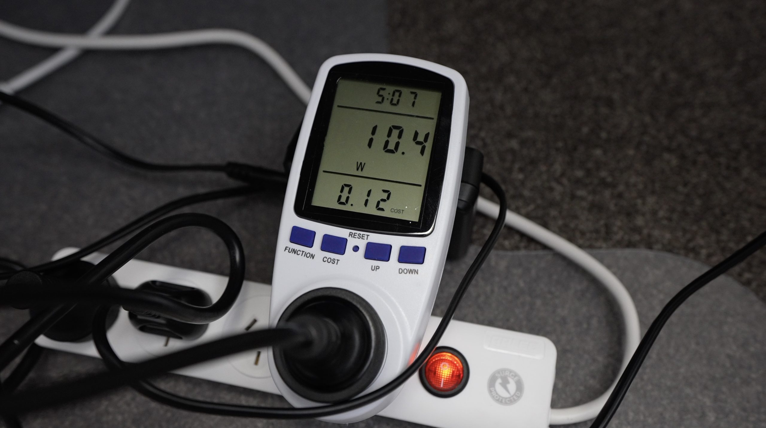
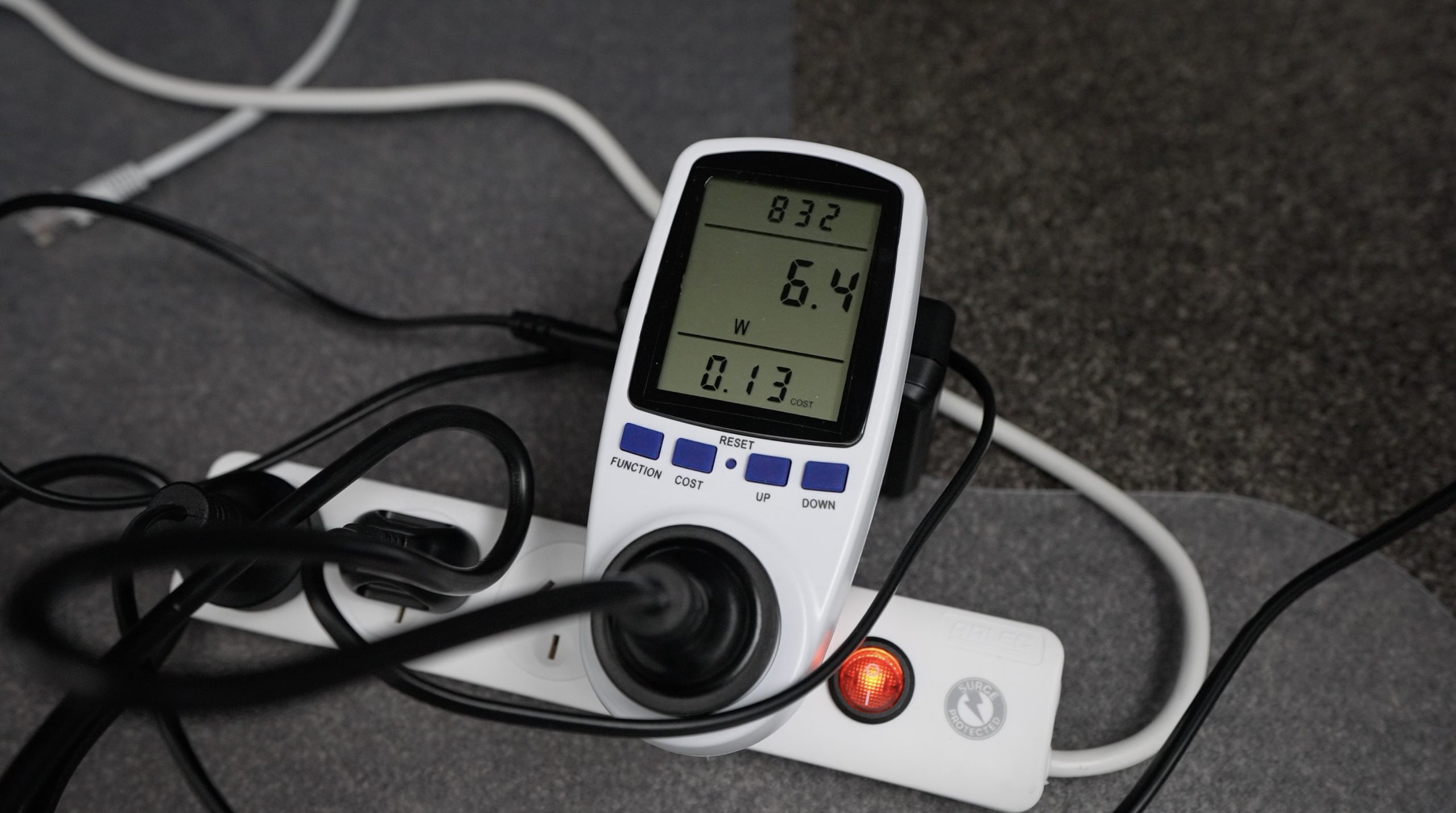
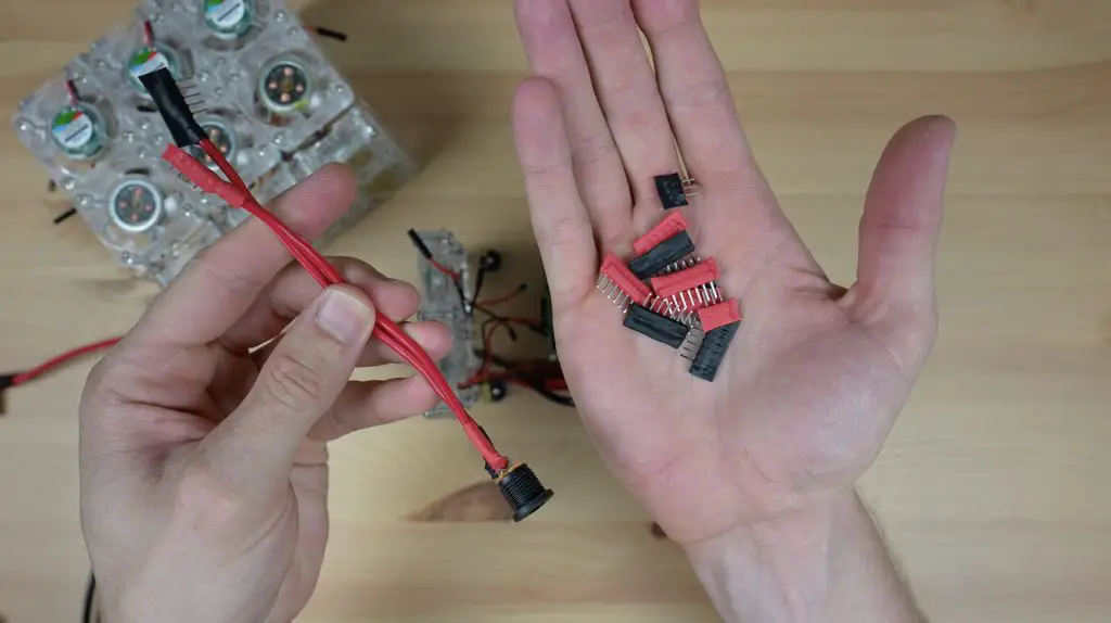
The next challenge is how to power the fans. Each one runs on 5V and draws around 0.1A. They’ll run individually on the Raspberry Pi’s GPIO pins, but when there are 24 of them, we easily exceed the capacity of the Pi. We probably even exceed the USB C power adaptor’s capacity with the Pi running as well. So I have to rig up another power supply just to run the fans – this power supply can do 5V 2.5A which is perfect.

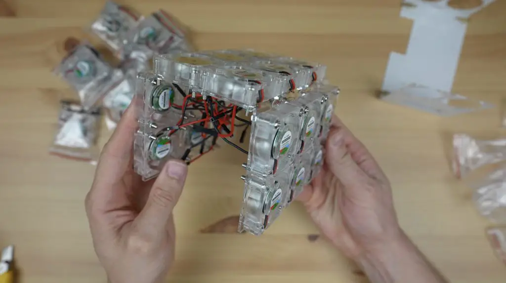
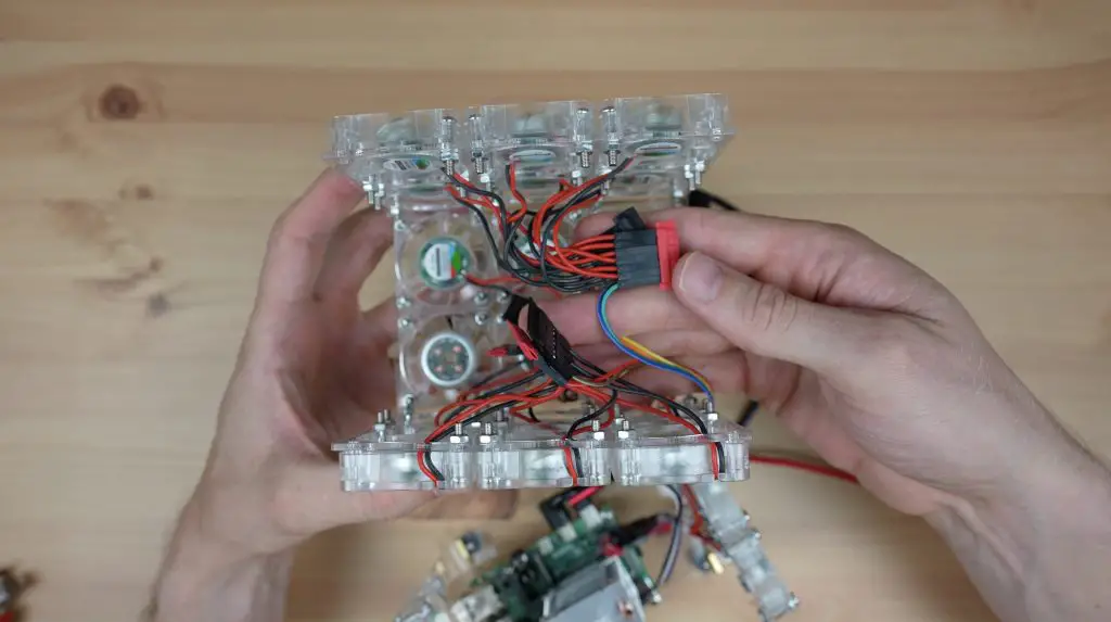
Now I just need to connect each of the fans to the power supply. I’ve made up a few connectors to connect the fans up in groups in a way that doesn’t have them all running through a single set of jumper leads, which would overload the leads.
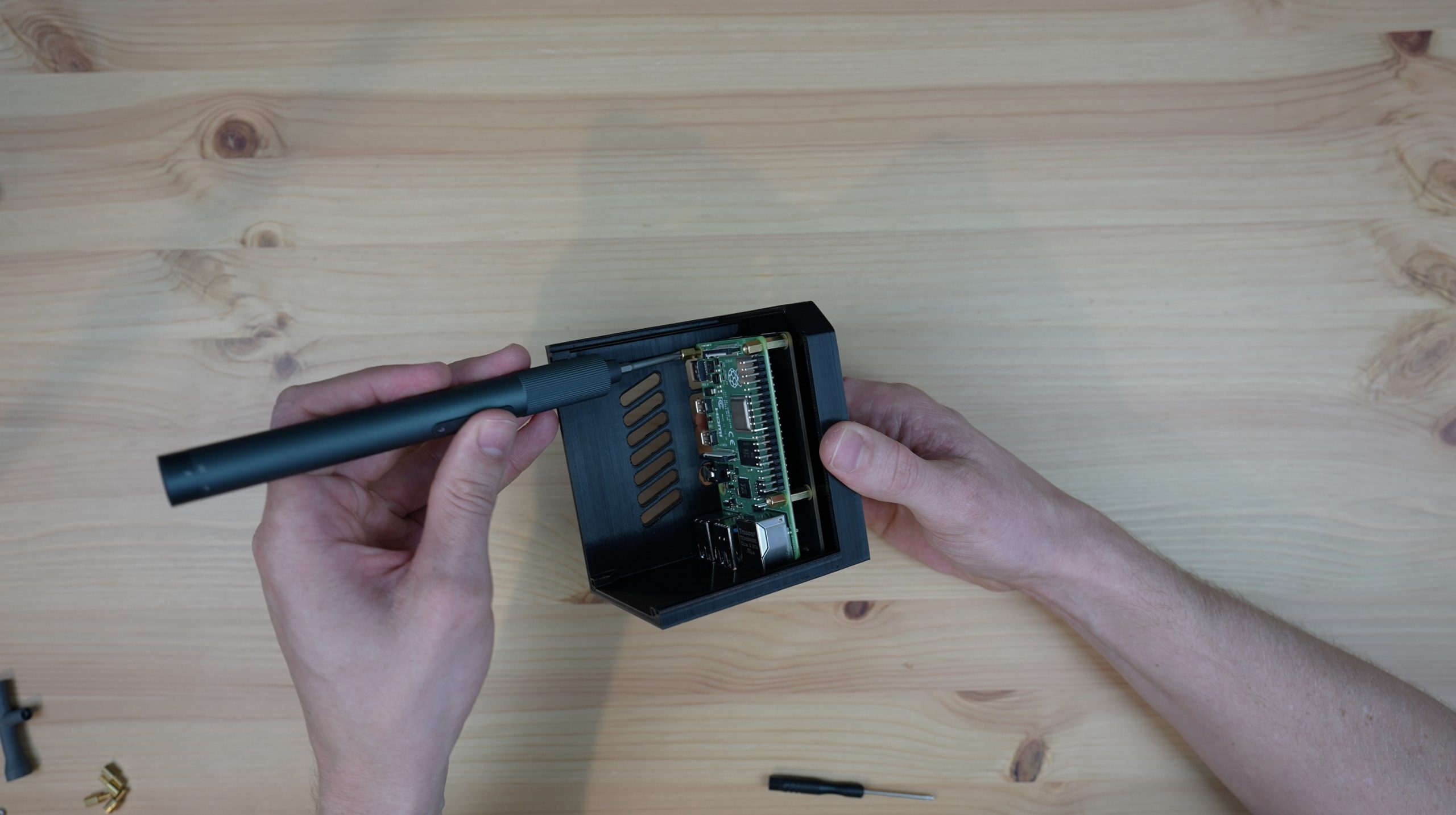
I then used some zip ties to neaten up the wiring and try to keep the wiring out of the fan blades. This also turned out to be a lot more difficult than I thought. There isn’t a lot of room within the case, so every time I put the two pieces together, some of the wiring landed up in a fan. After a bit of frustration, I eventually managed to sort it out and get the fans spinning freely.
I’m not going to power it up just yet, let’s first backtrack a little and let me show you the results from my first two tests.
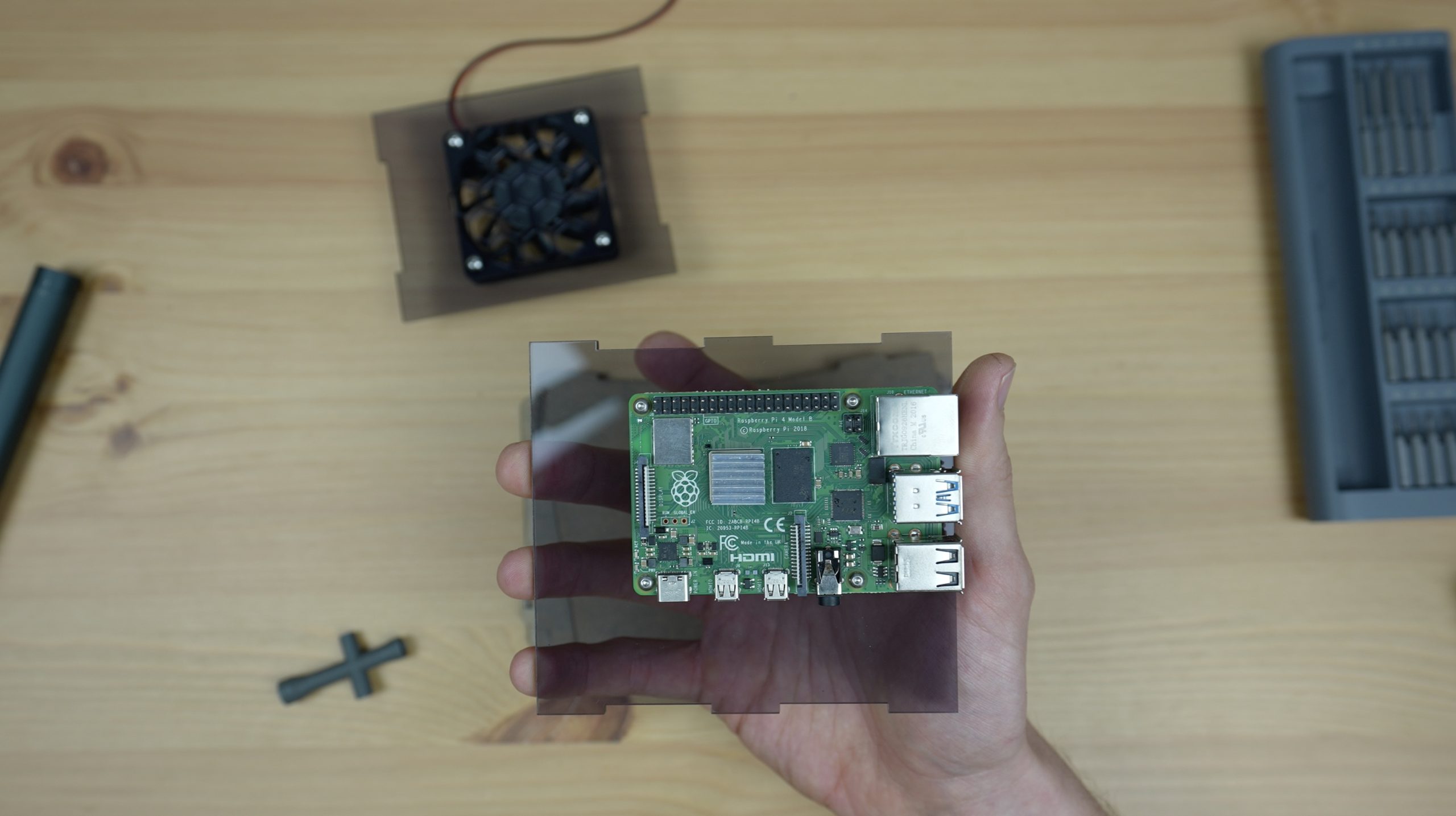
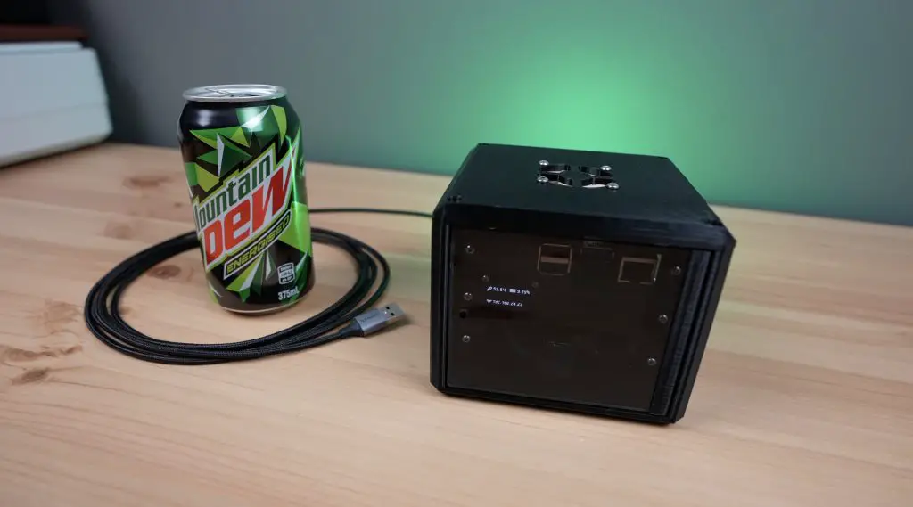
Testing My Original Desktop Case Design
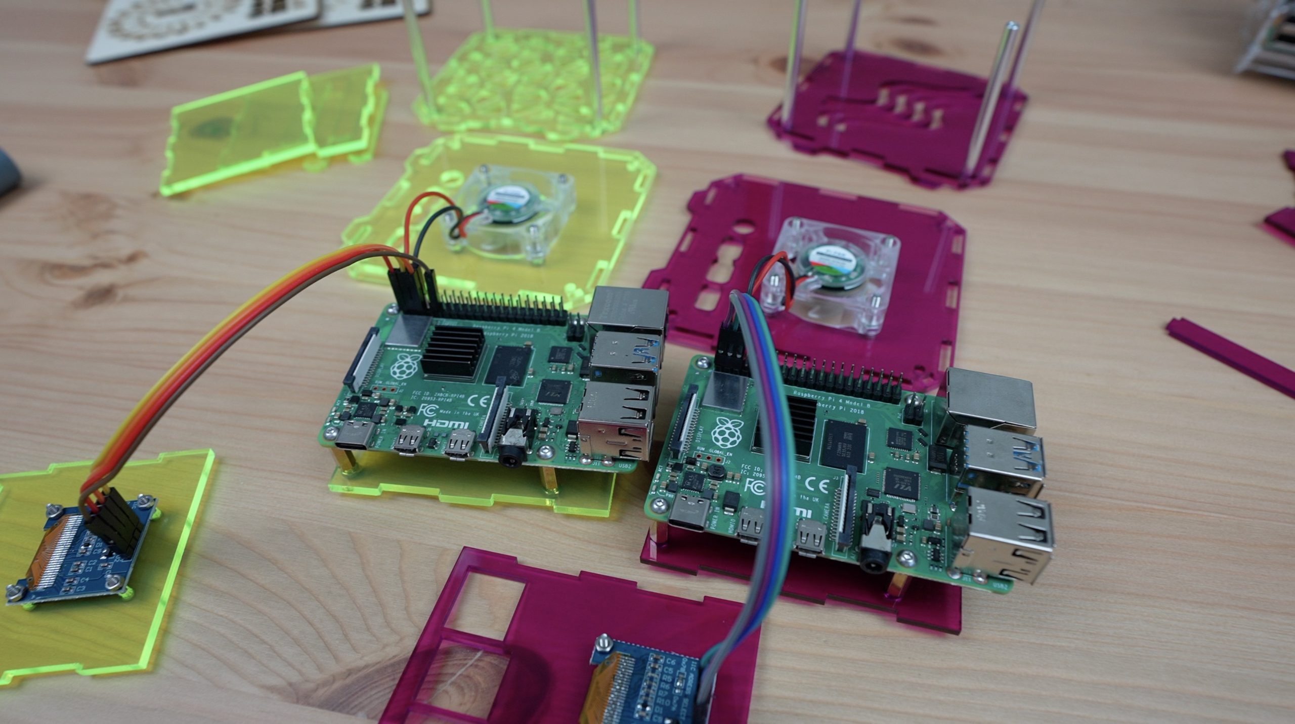
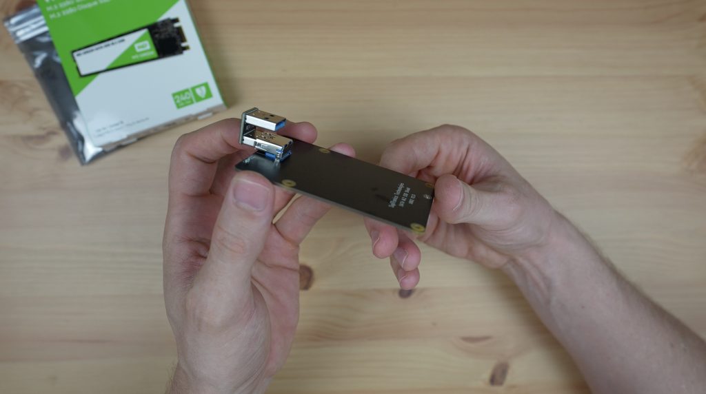
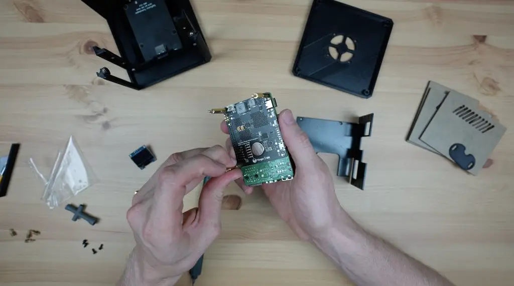
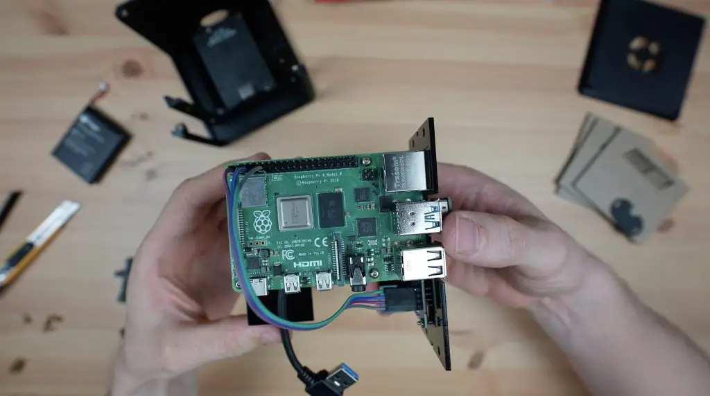
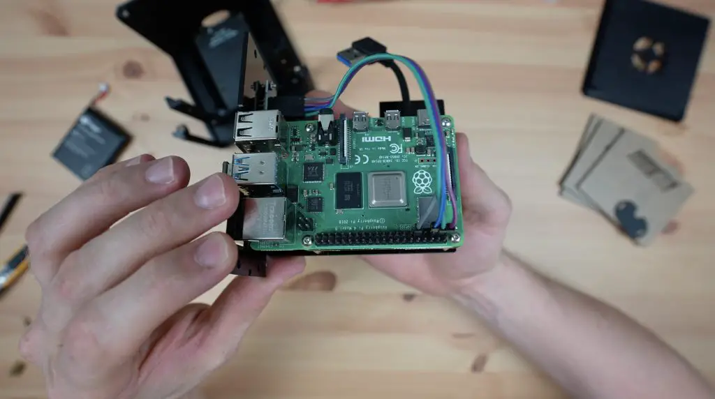
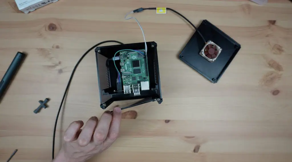
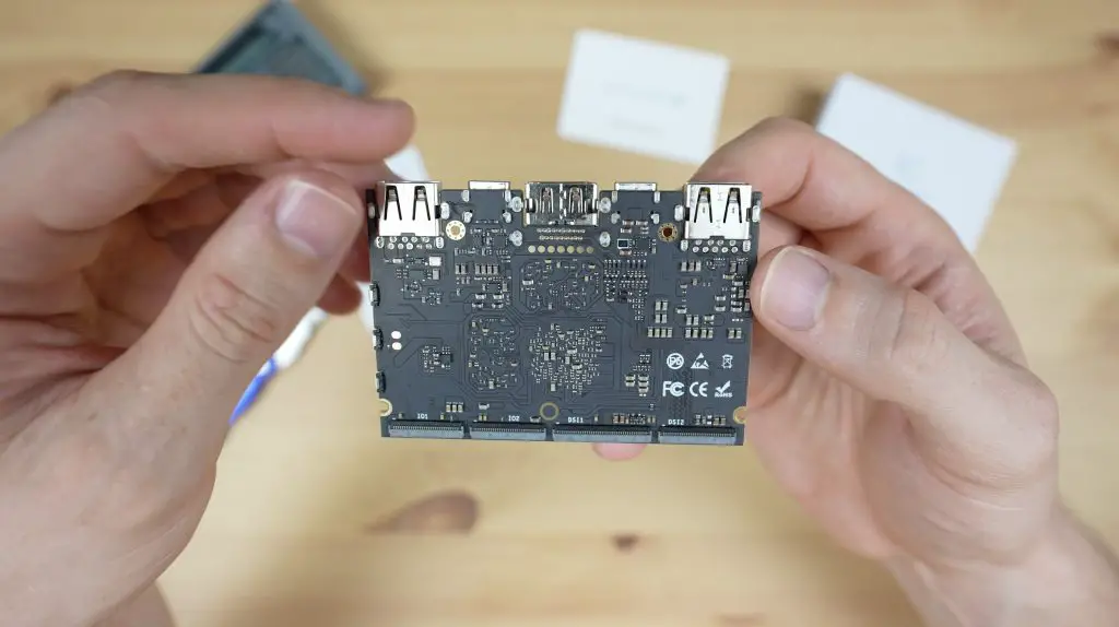
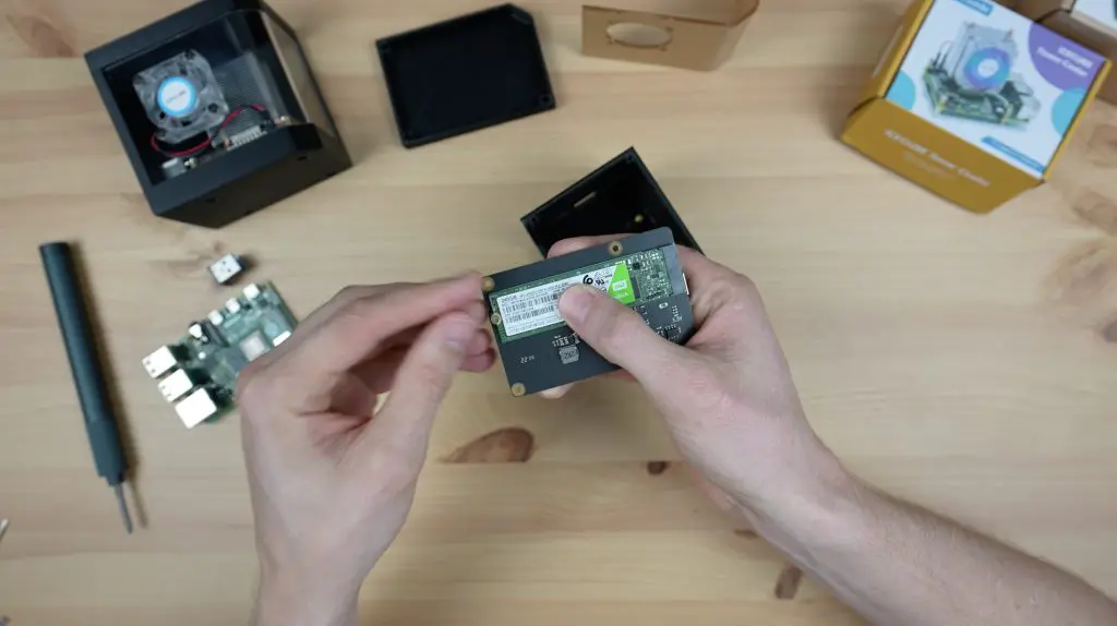
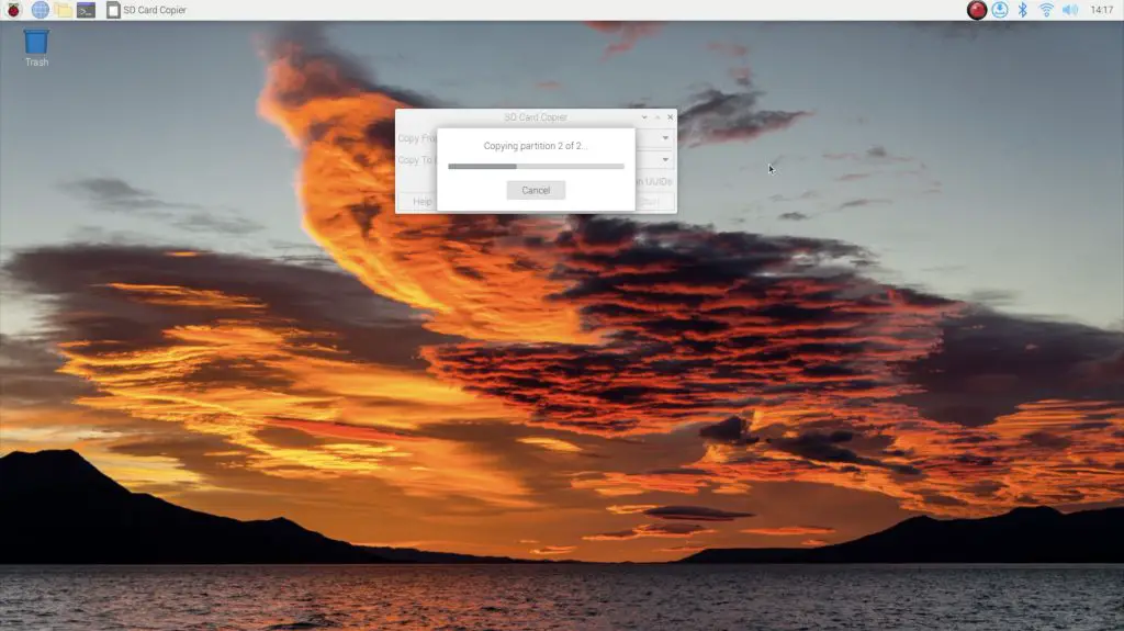
I wanted to use the same Raspberry Pi across all tests for consistency, so the Pi that is currently in the fan case is the same one that I used earlier for these tests.
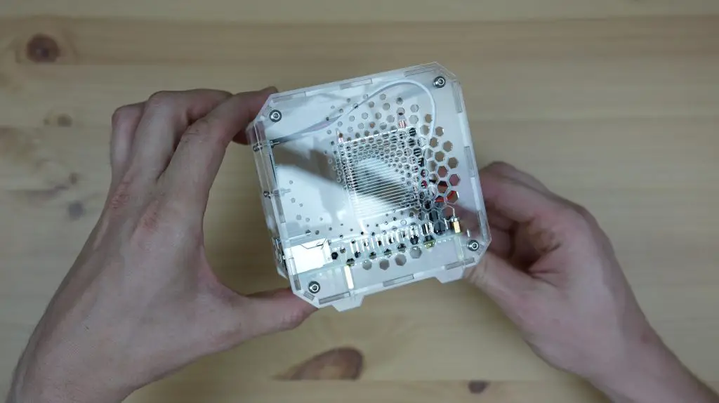
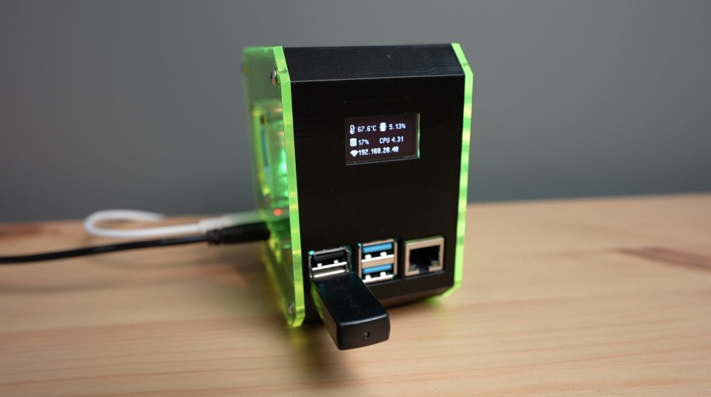
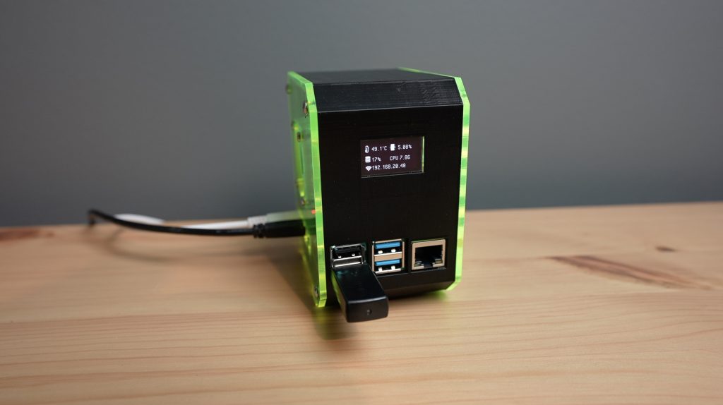
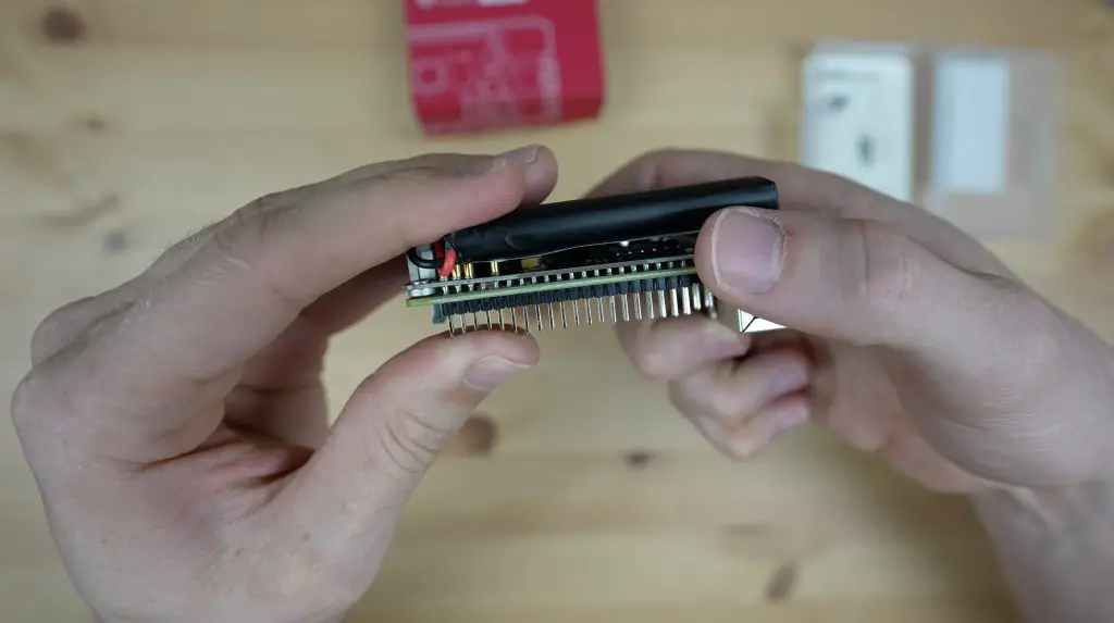
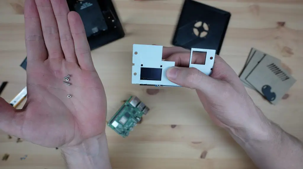
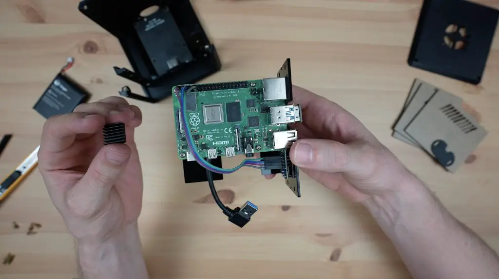
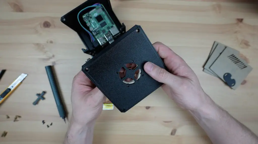
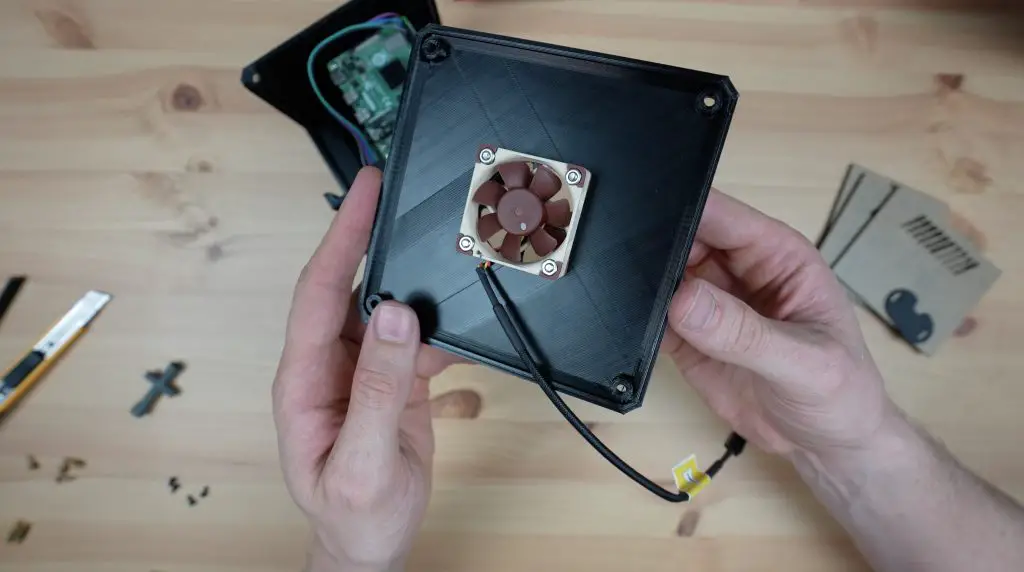
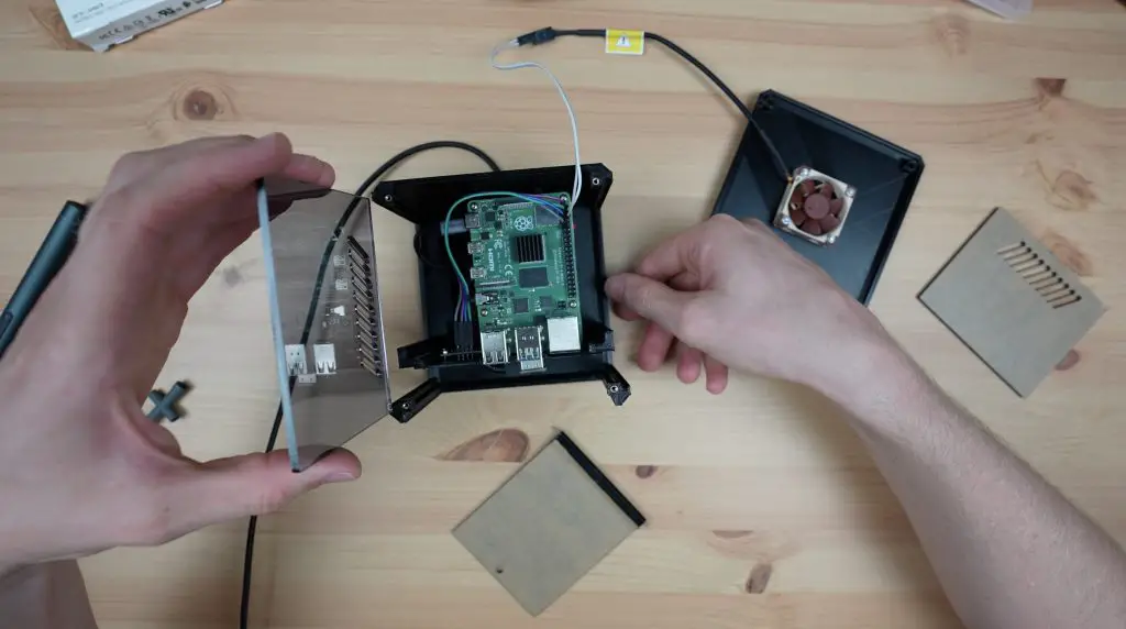
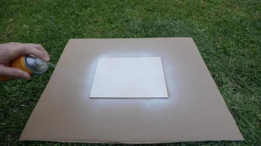
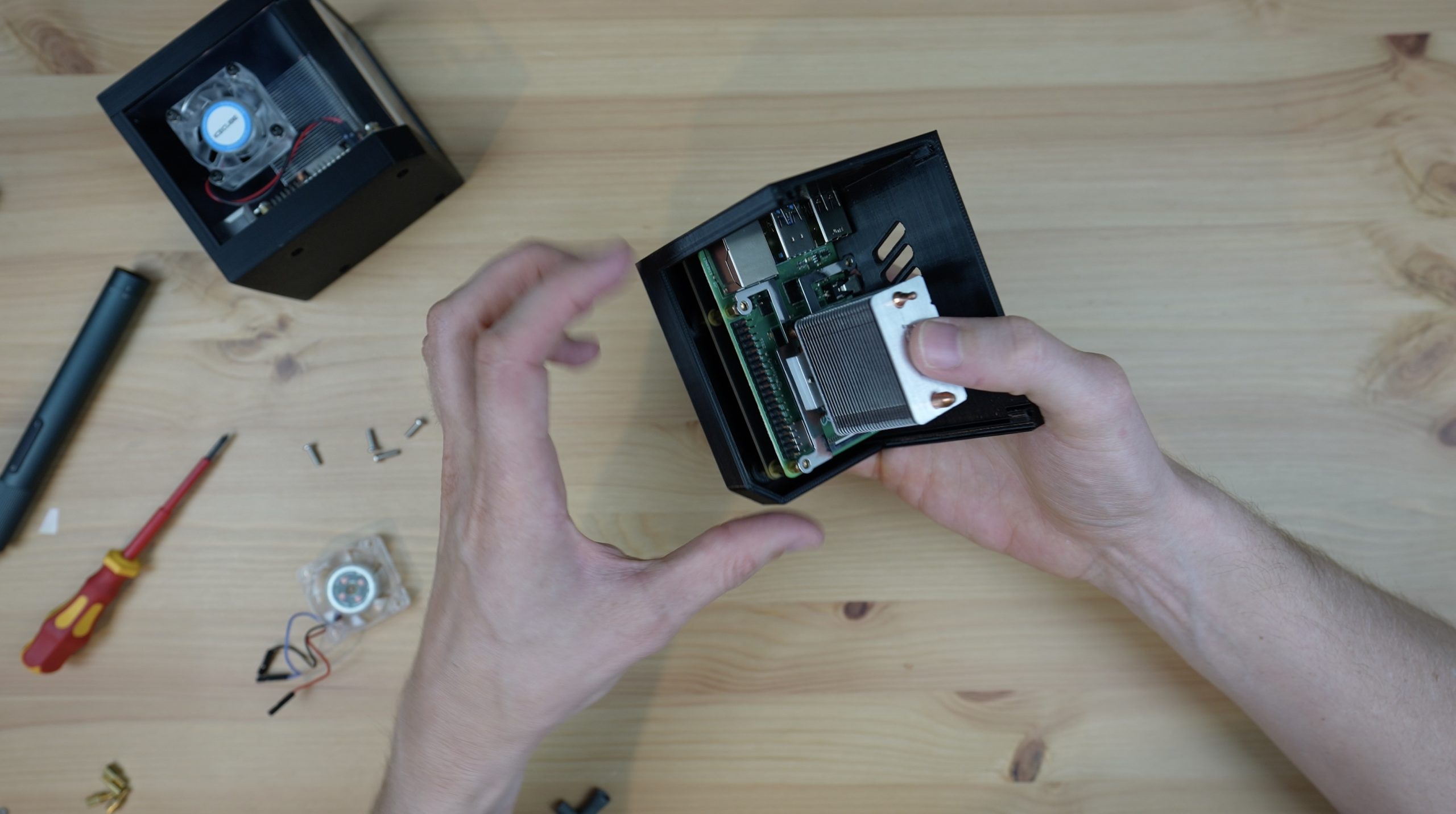
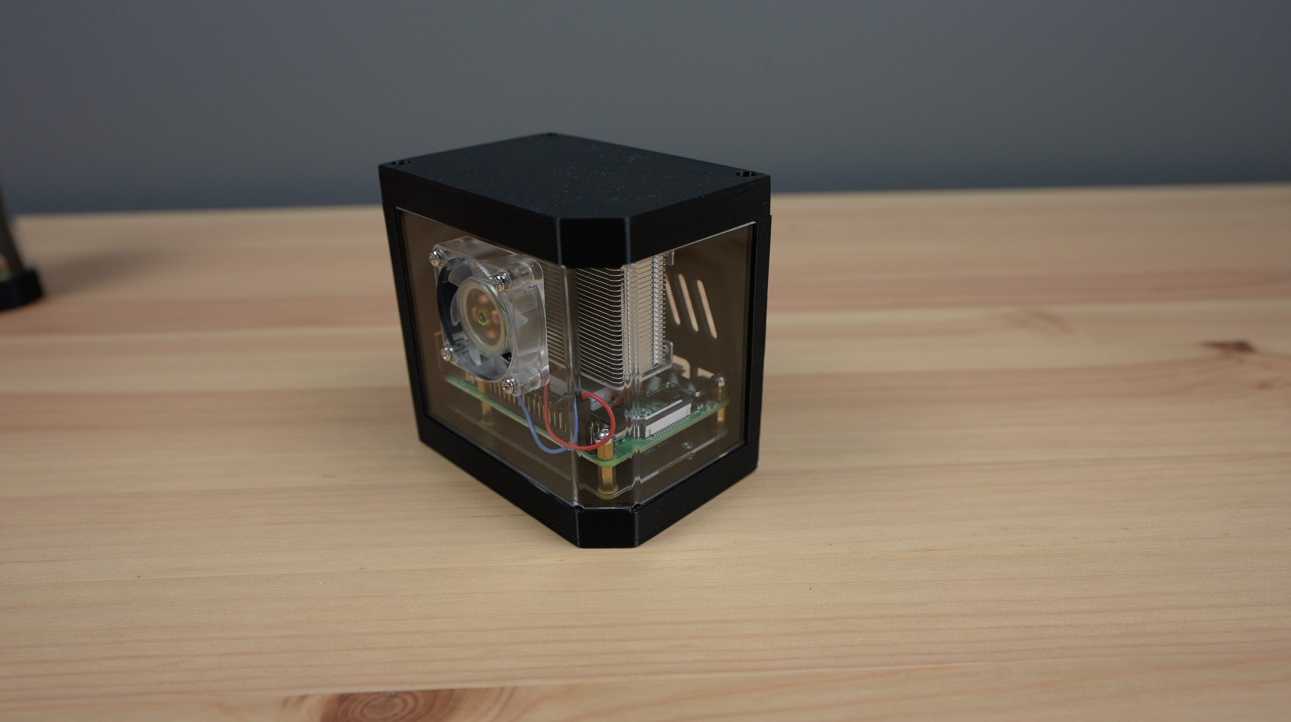
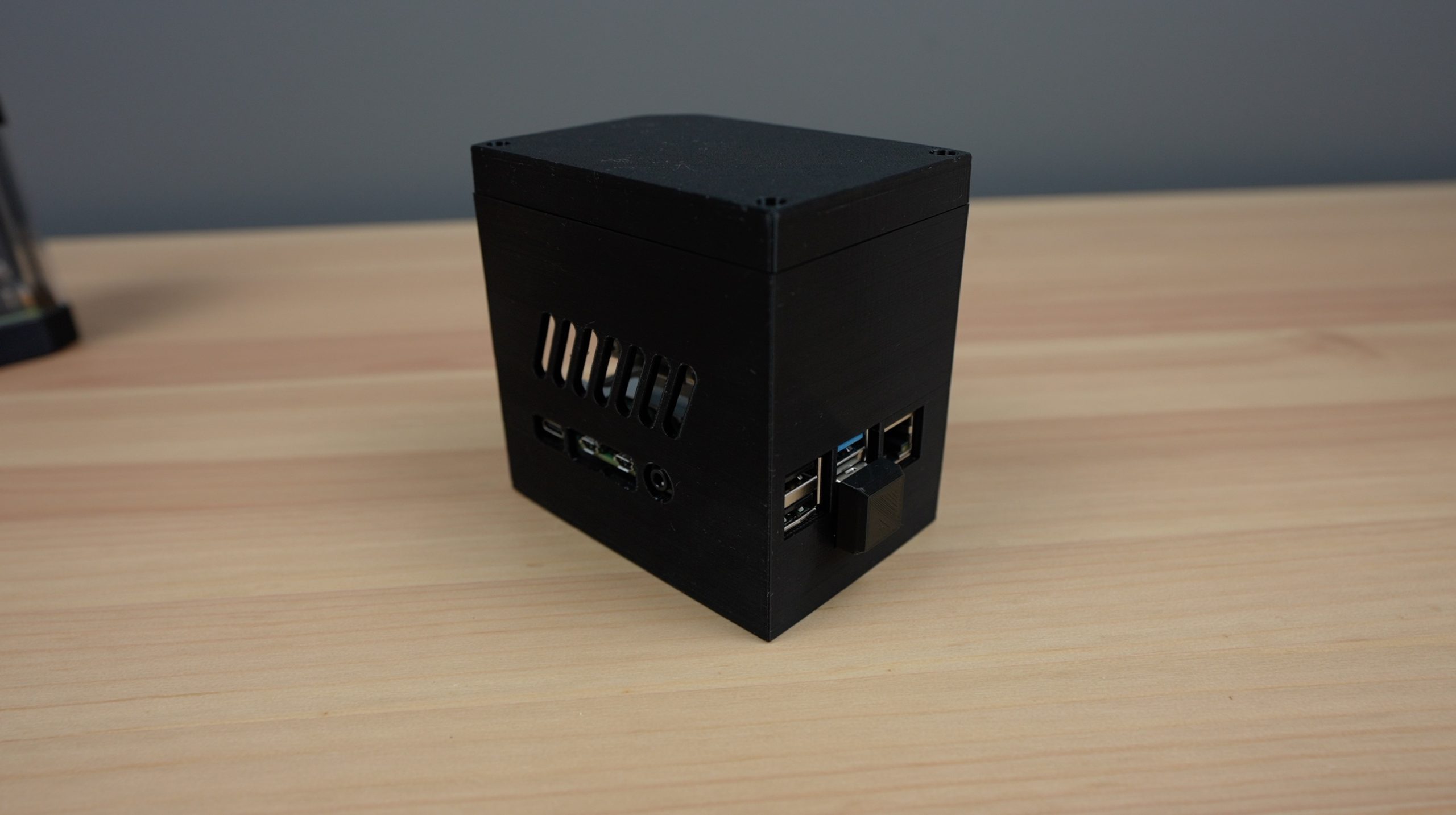
For the first test, I put a small aluminium heatsink onto the Pi and then put it into my desktop case. It’ll be cooled by a single fan on the side of the case.
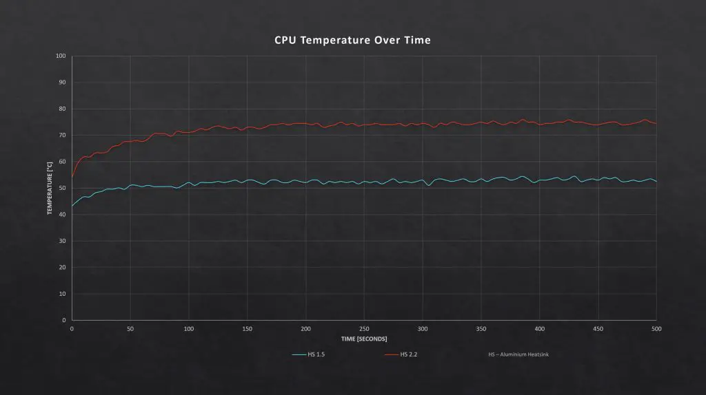
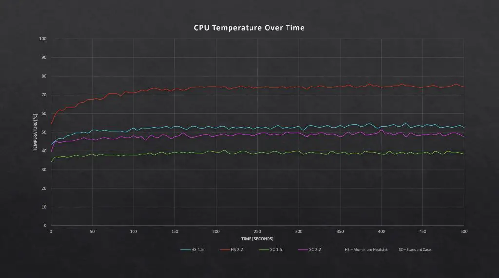
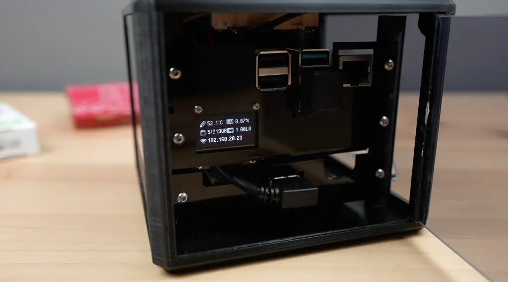
I booted it up and then ran CPU burn with the CPU clock frequency at the standard 1.5Ghz. The temperature actually stayed lower than I expected and it stabilised at around 53 degrees after 3 minutes.
I then overclocked the Pi to 2.2Ghz and ran the test again. This resulted in a significantly higher running temperature but still didn’t thermal throttle and stabilised at around 75 degrees after 4 minutes.
Here are the results from the Aluminium Heatsink test:
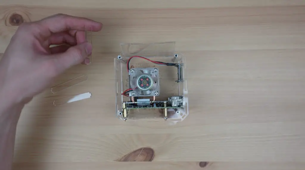
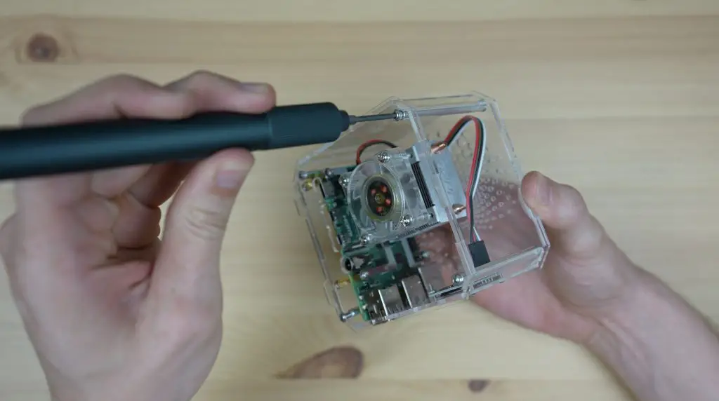
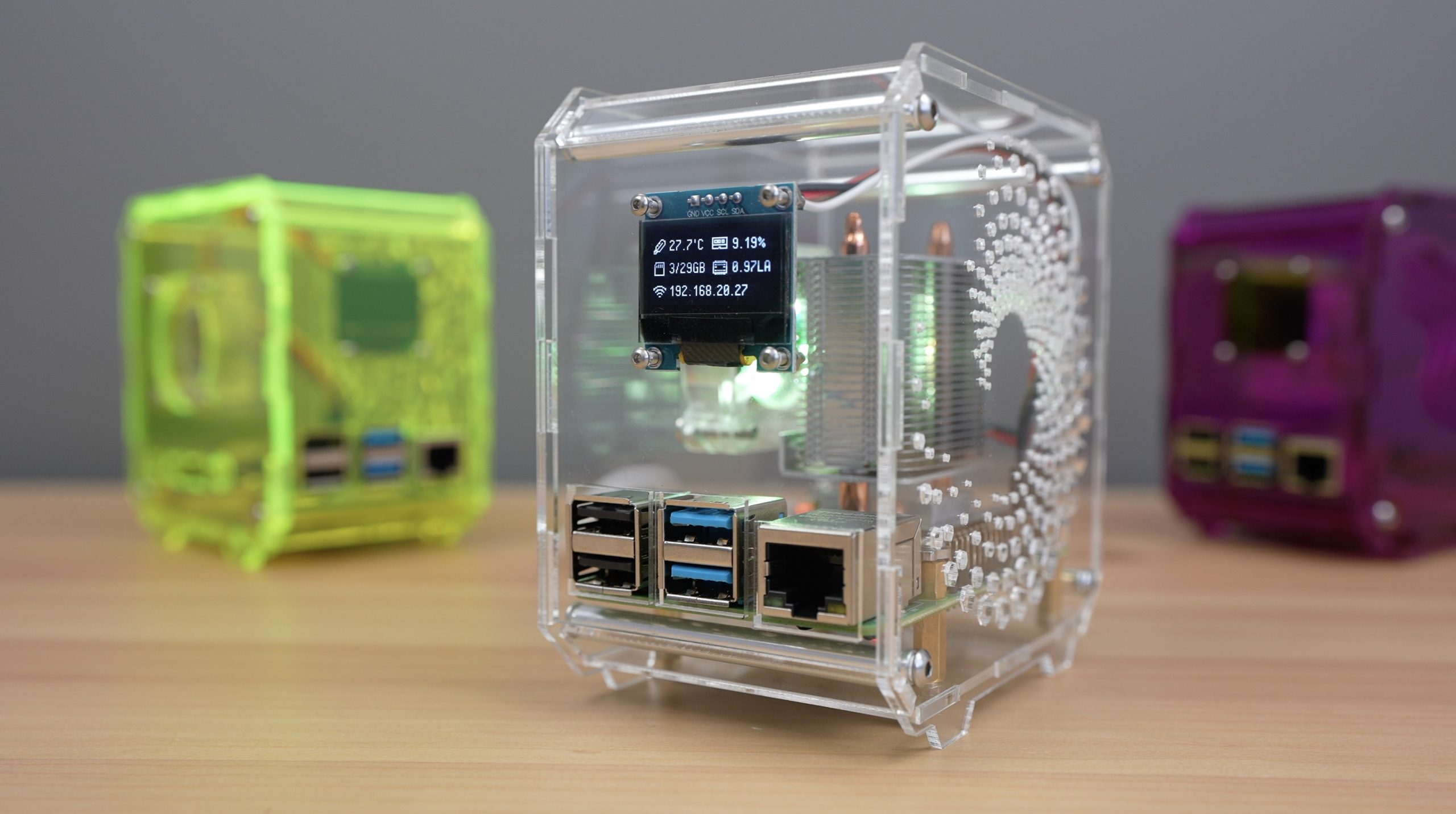
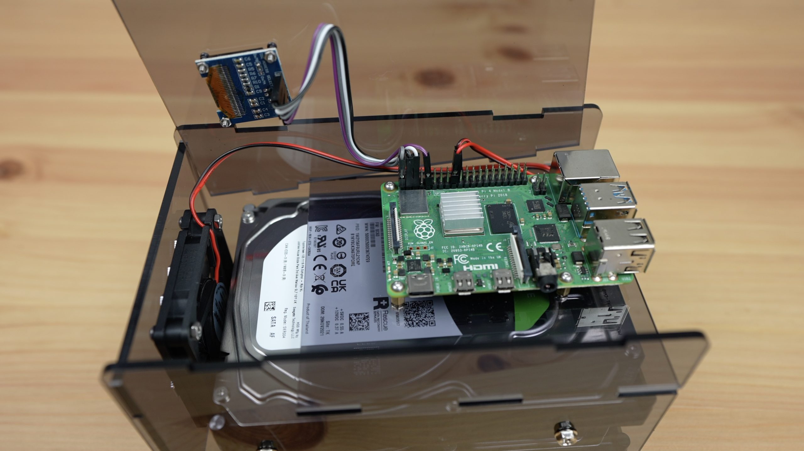
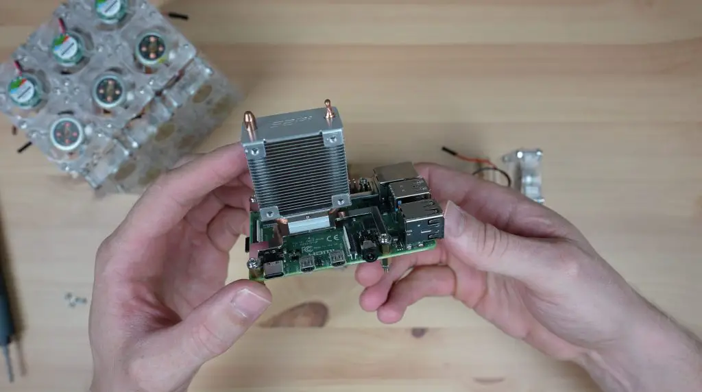
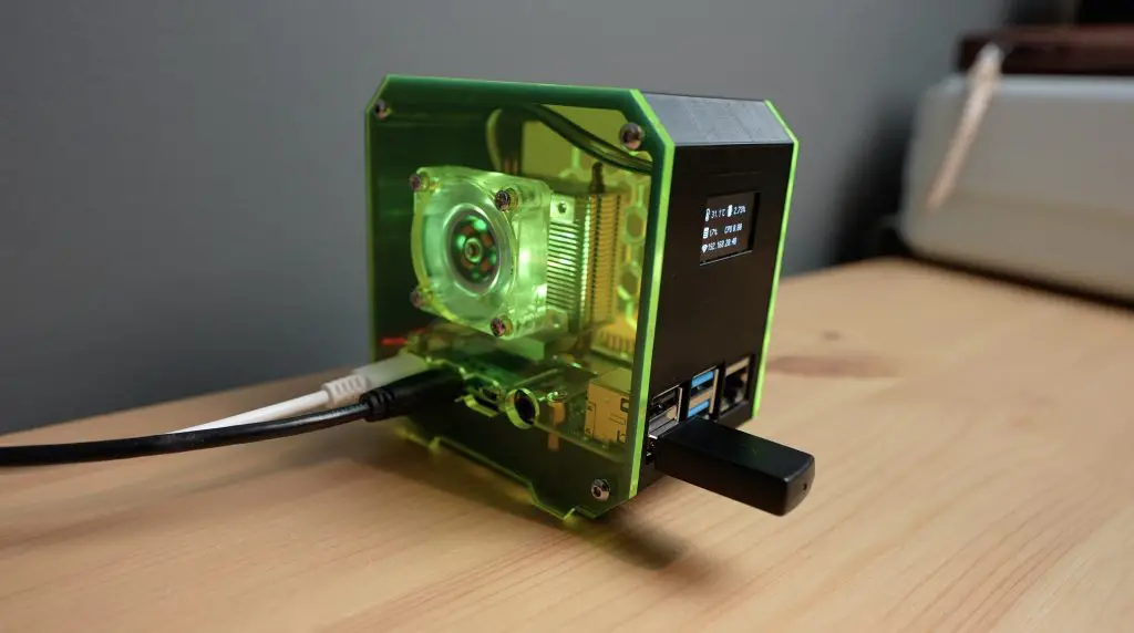
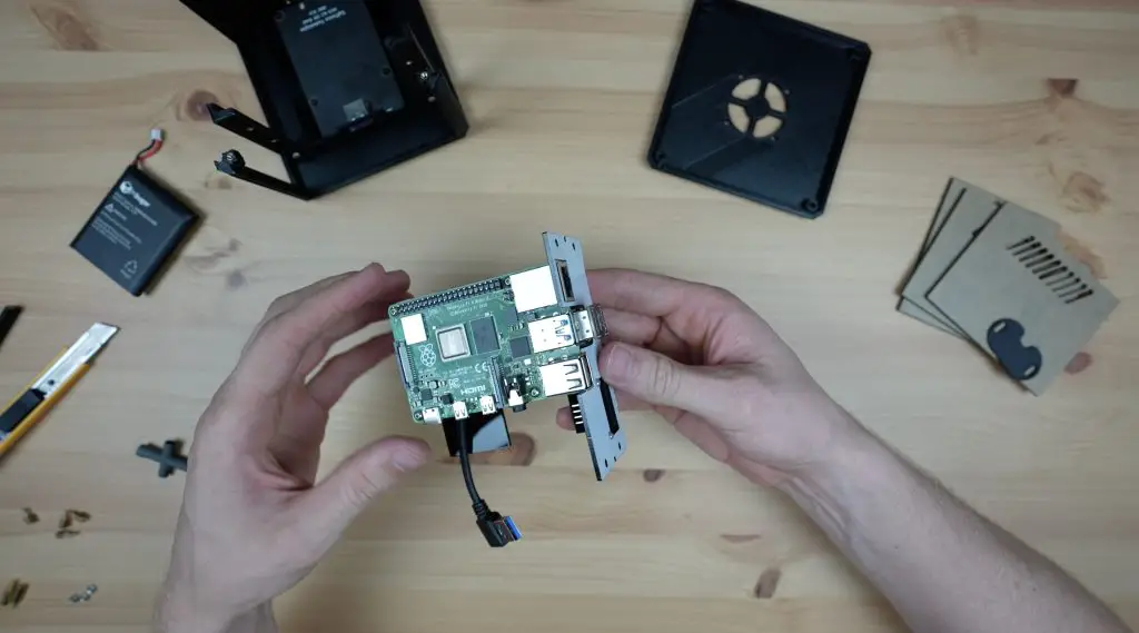
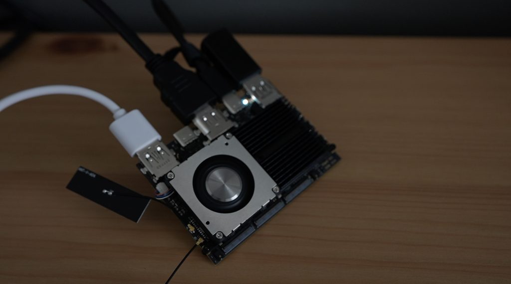
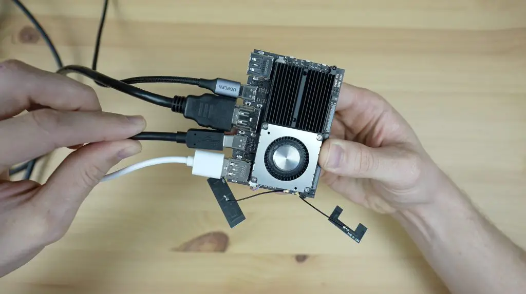
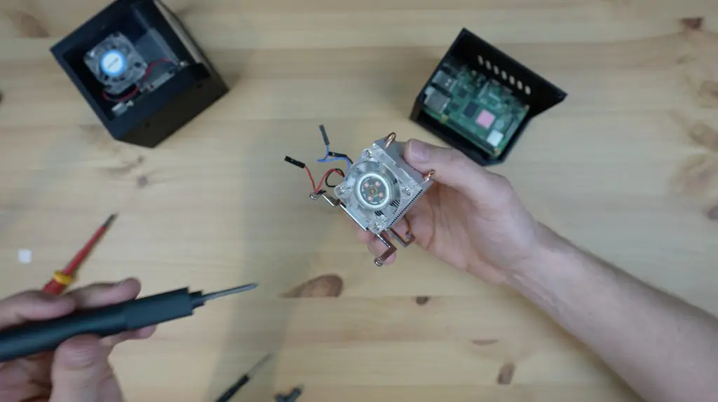
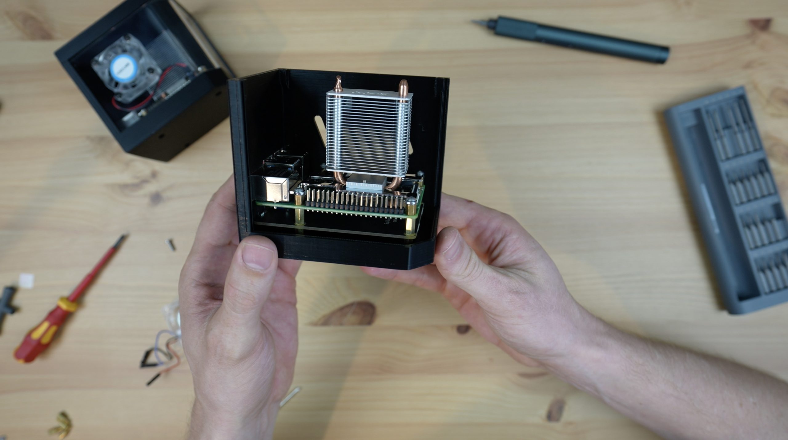
For the second test, I put the Ice Tower onto the Pi as I usually do with my case designs. This also has a single fan which is mounted directly onto the side panel of the case, pushing air into the case and onto the Ice Tower cooler, and vents out on the opposite side.
The 1.5Ghz test stabilised at about 39 degrees after 2 minutes.
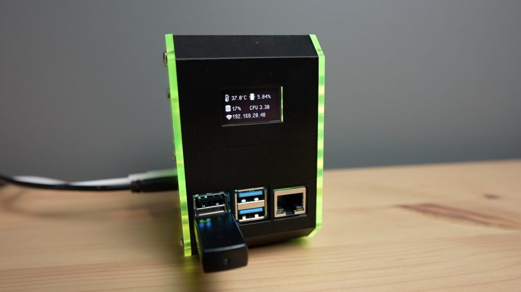
The 2.2Ghz test stabilised about 10 degrees higher at 49 degrees but took about 4 minutes to get there.

So these are the results from the first two tests, which we’ll be looking to beat with more fans:
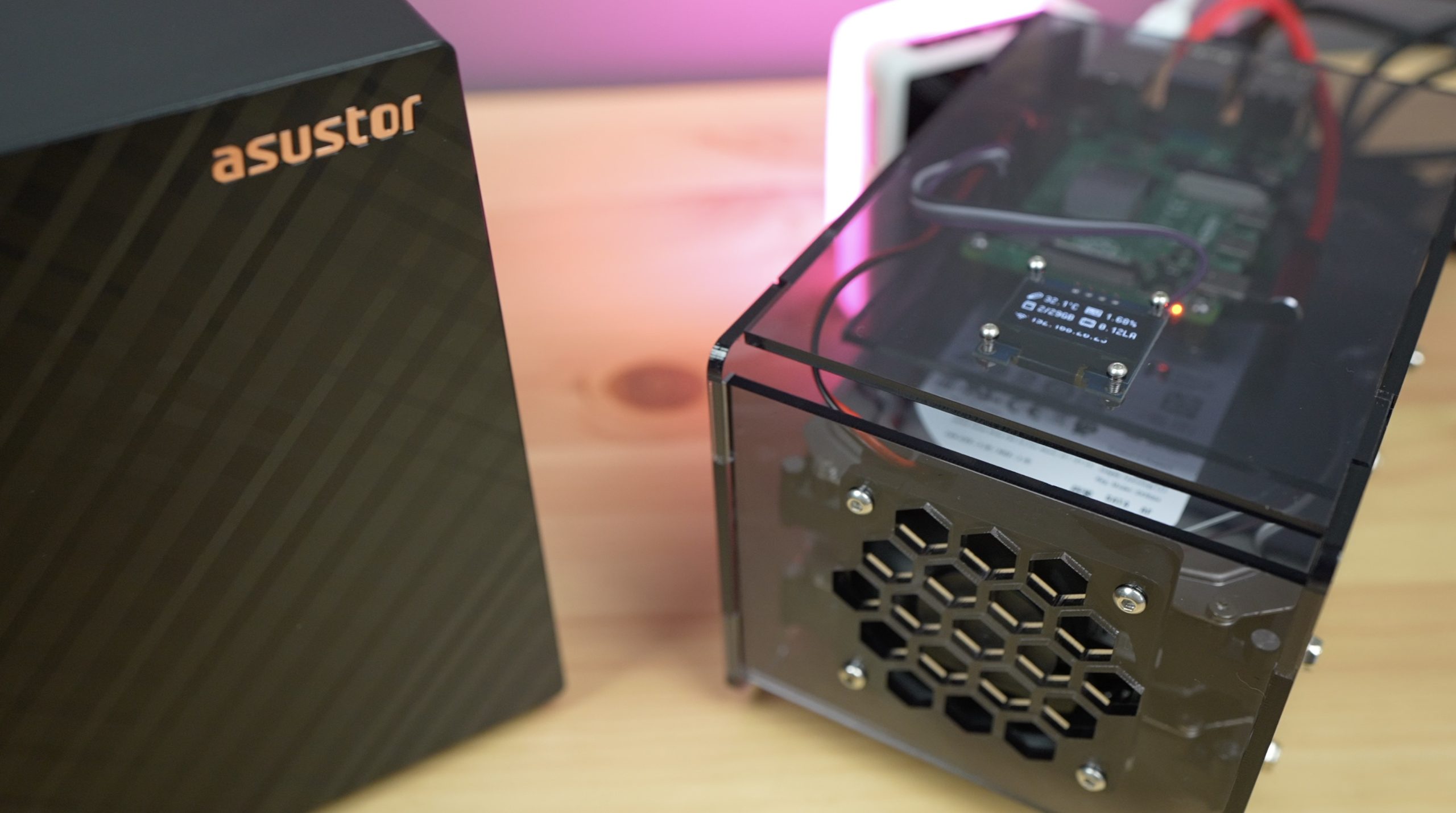
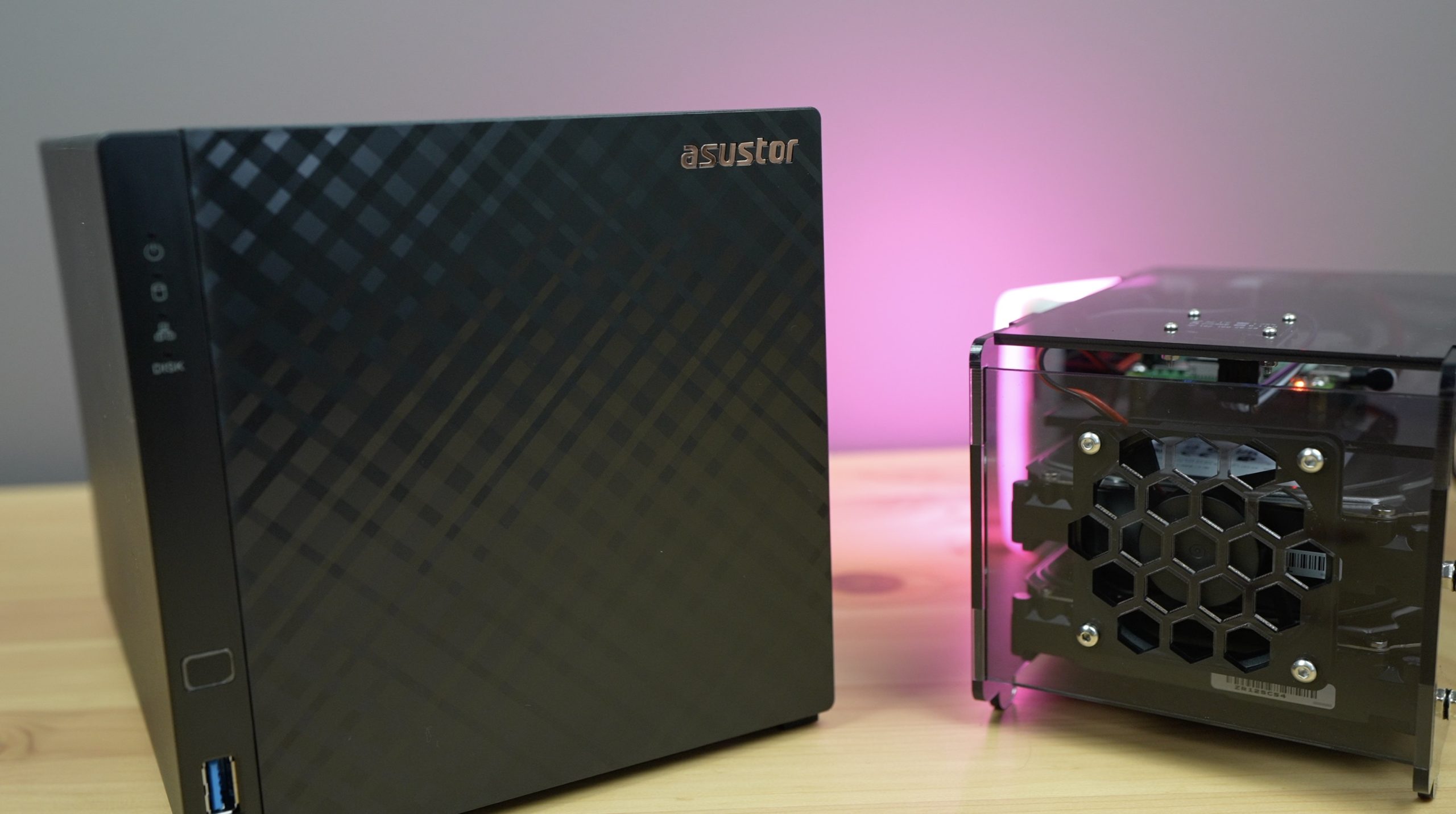
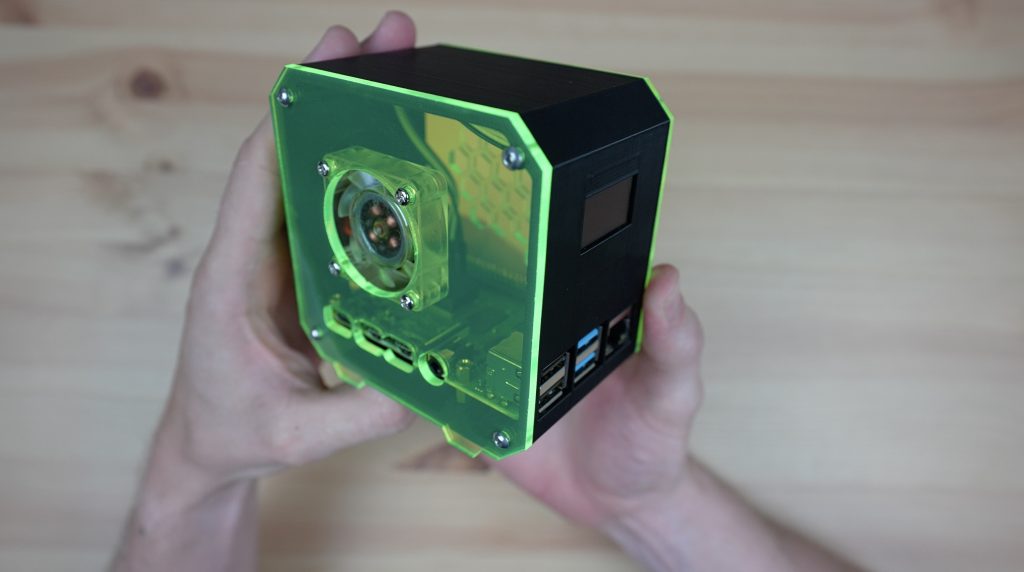
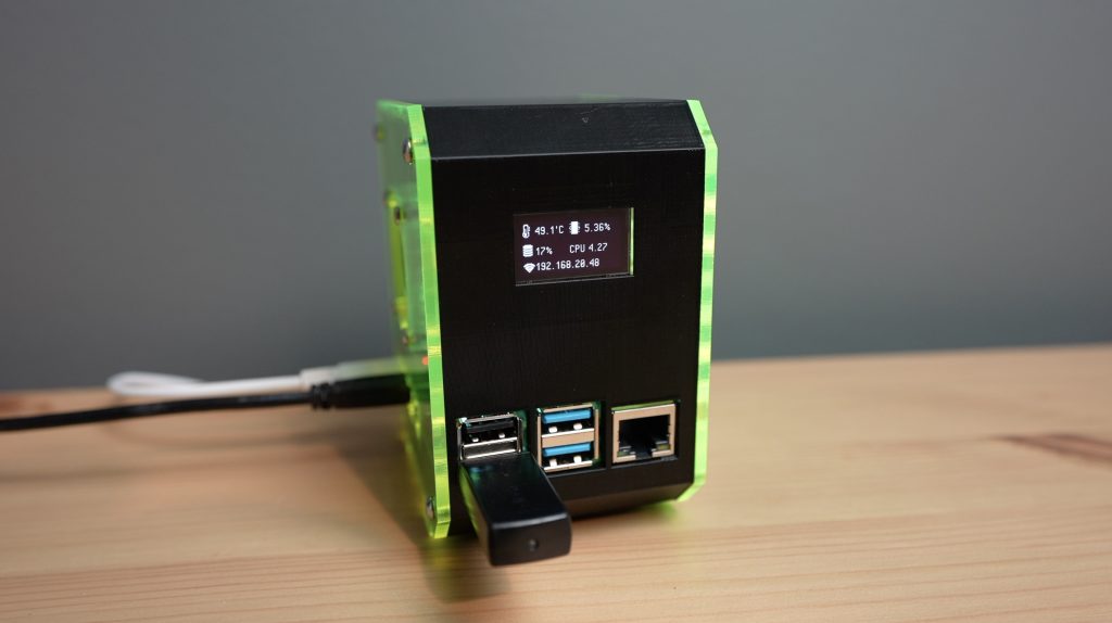
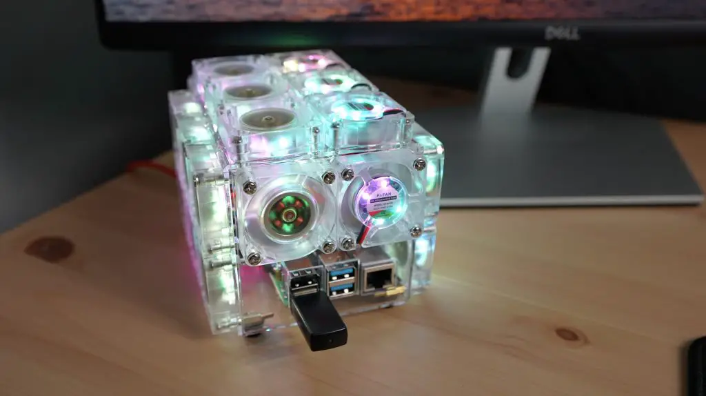
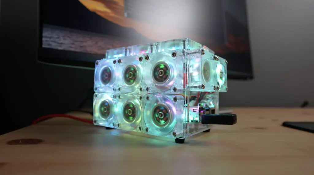
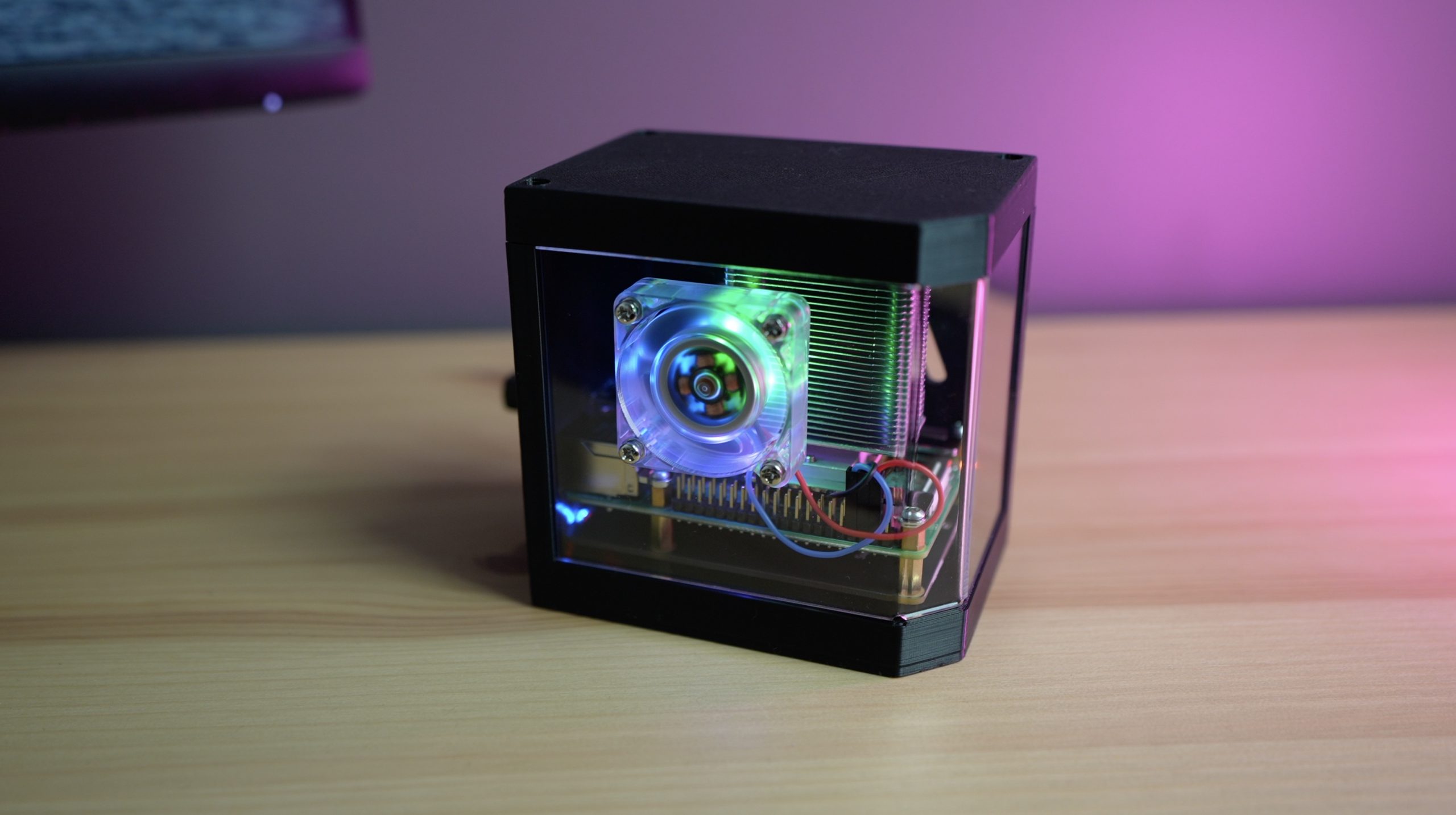
Testing The Fan Case
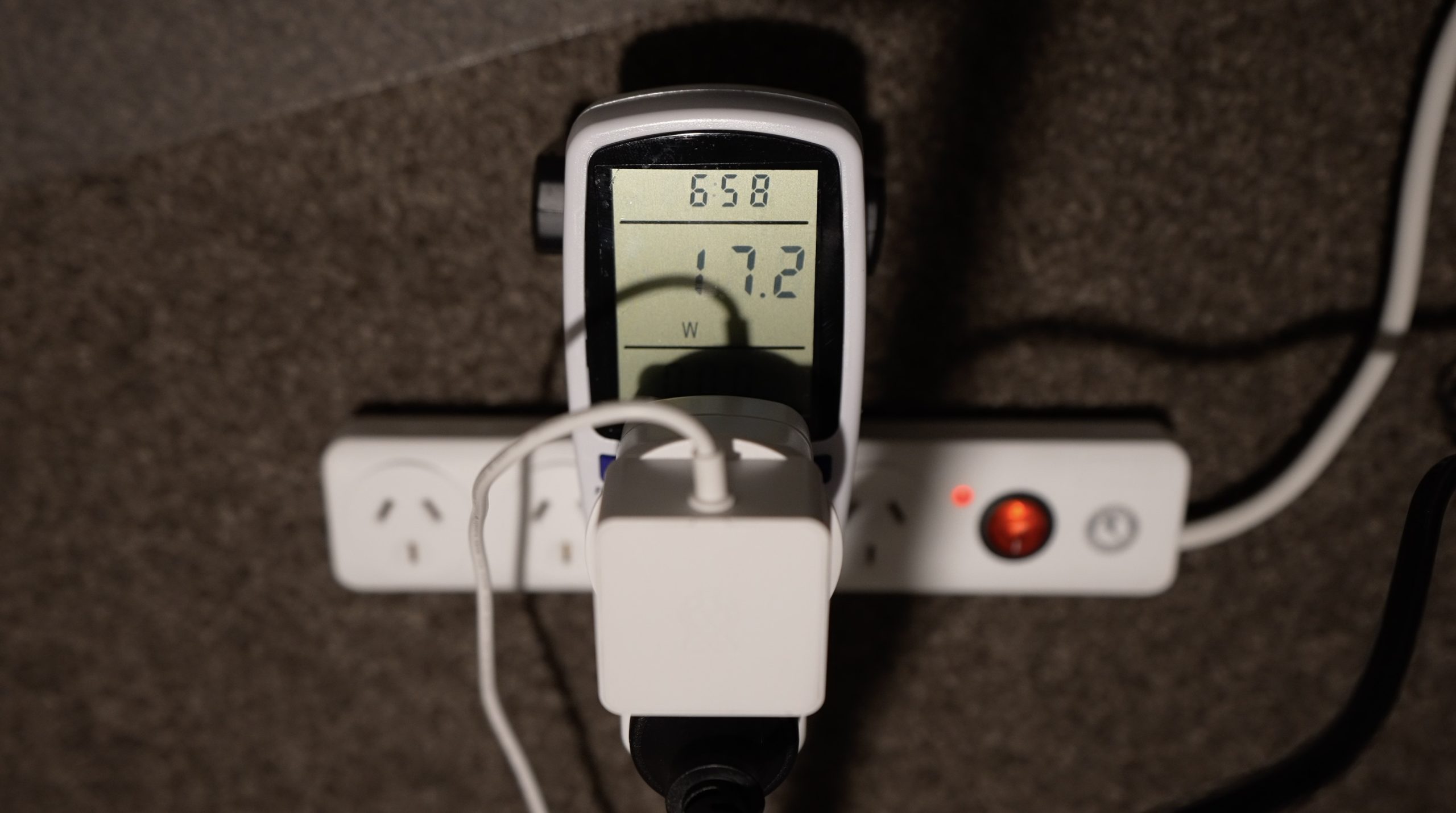
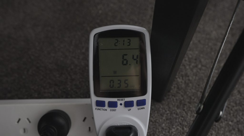
Let’s start out by getting the fans powered up.
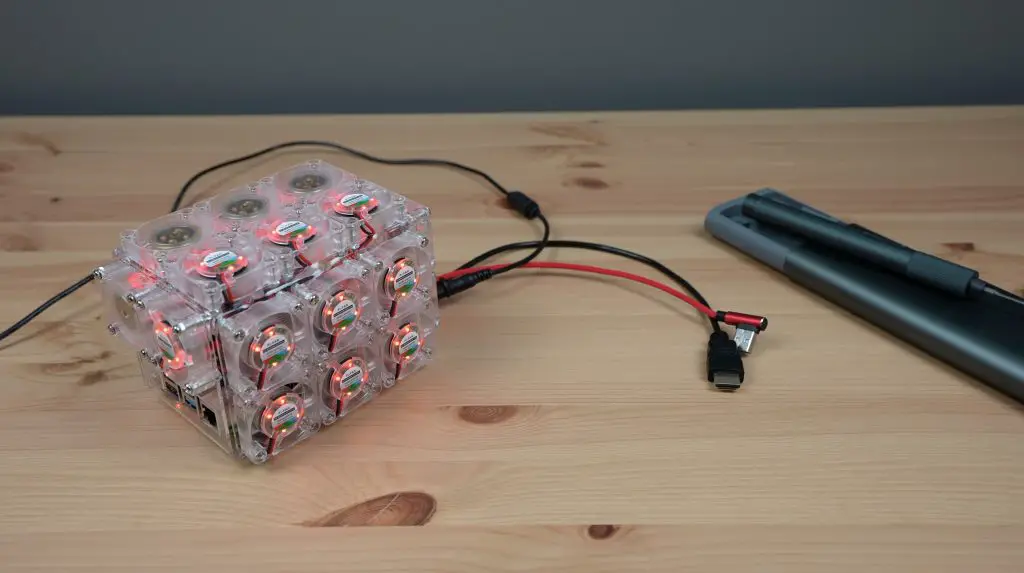
I wasn’t sure what to expect, but to me, it was somewhat underwhelming. You’ll need to watch my video linked at the beginning of the post, but I expected a bit more noise and to feel a lot more airflow around the case. It still looks pretty cool though.
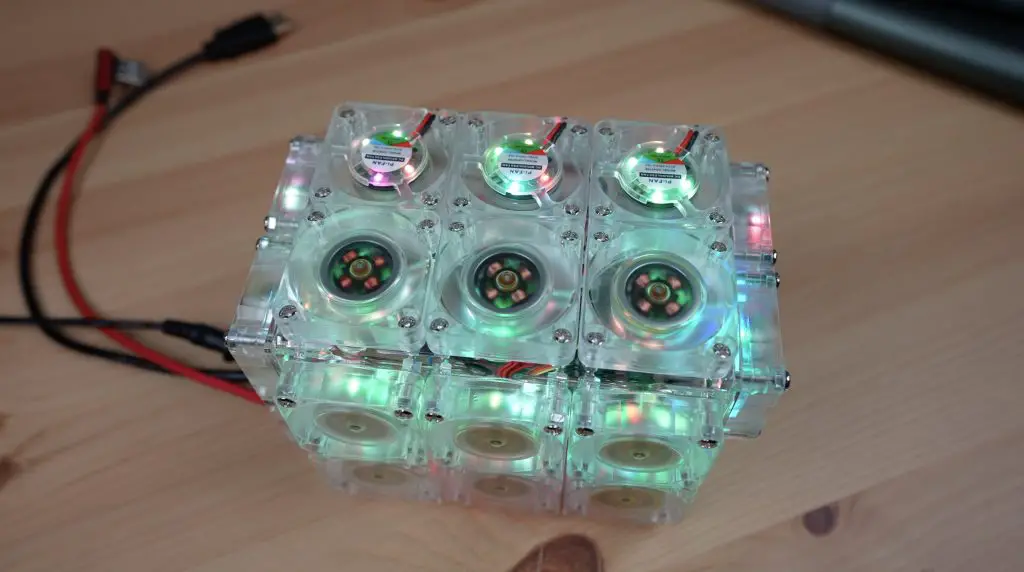
It was also quite nice to see the fans all start off the same colour and run the same RGB loop for a few seconds before slowly drifting off into a mix of colours.
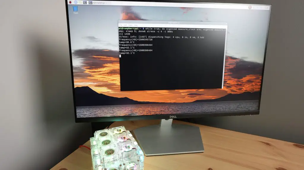
Next, let’s boot up the Pi and see how it handles the test.
First, let’s run the test at 1.5Ghz. The fans were making a difference at the start, our starting temperature was a little over 3 degrees lower than with the Ice Tower. The temperature jumped up to 34 degrees quite quickly but stabilised quickly as well.
Next let’s reboot it at 2.2Ghz and try again.
Our starting temperature is about 7 degrees warmer than at 1.5Ghz, so let’s see what it stabilises at.
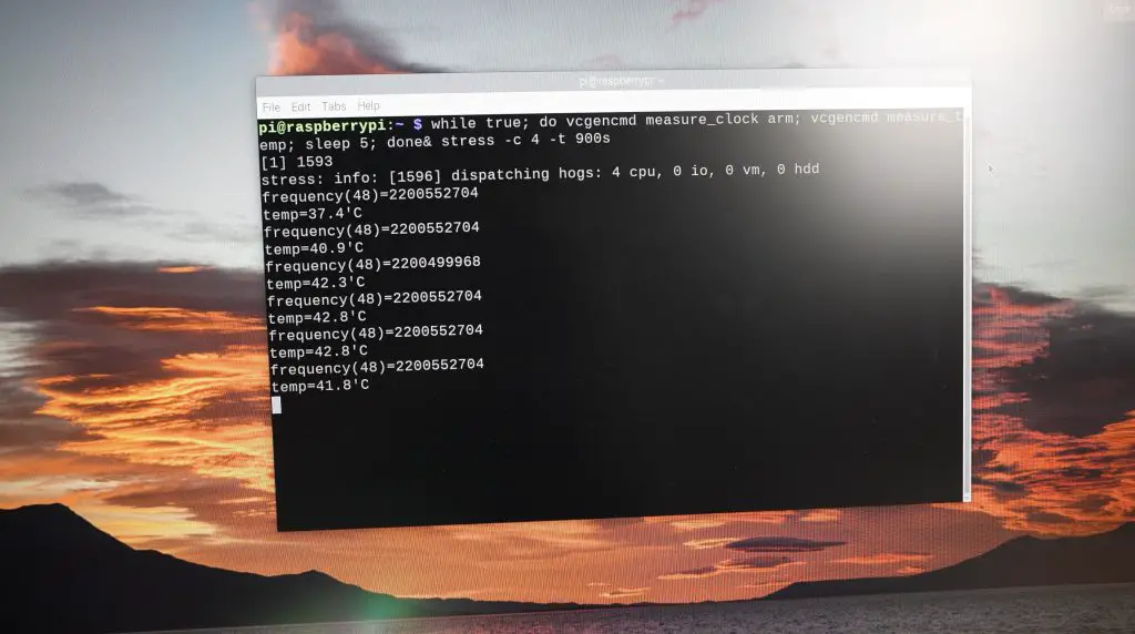
With the tests done, the results are in. The fan case stabilised at 35 degrees at 1.5Ghz and 44 degrees at 2.2Ghz, both after around 3 minutes.
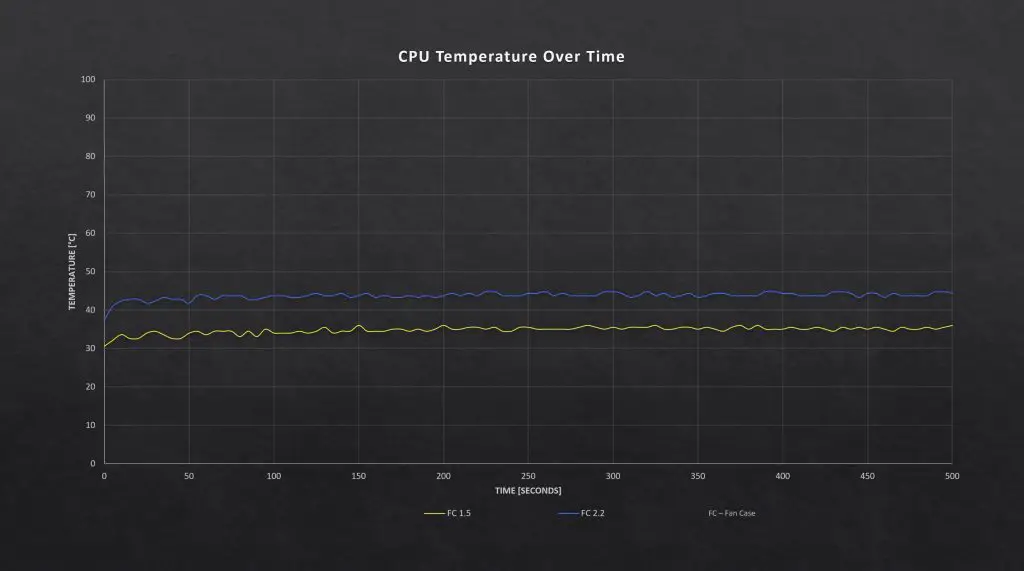
Comparing The Results From All 6 Tests
Here are the results from all 6 tests:
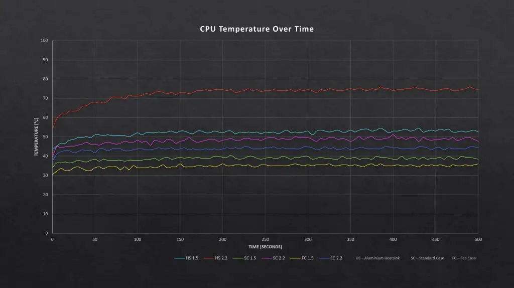
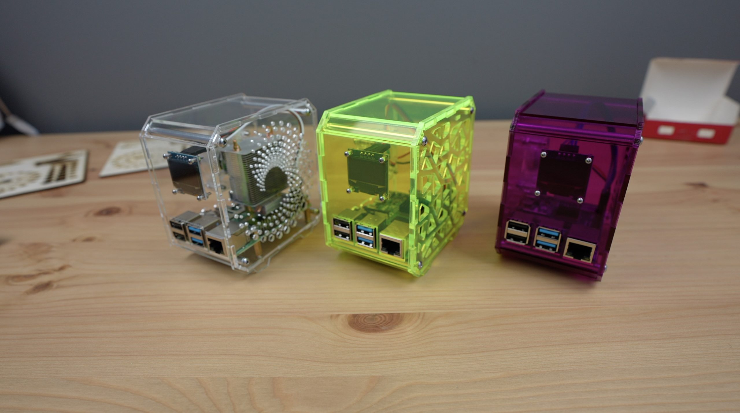
So the fan case did have an improvement over the standard case, but not in a way that I’d consider a dramatic improvement. The temperature decreased by an average of 4 degrees when running the 24 fans in place of the single fan.

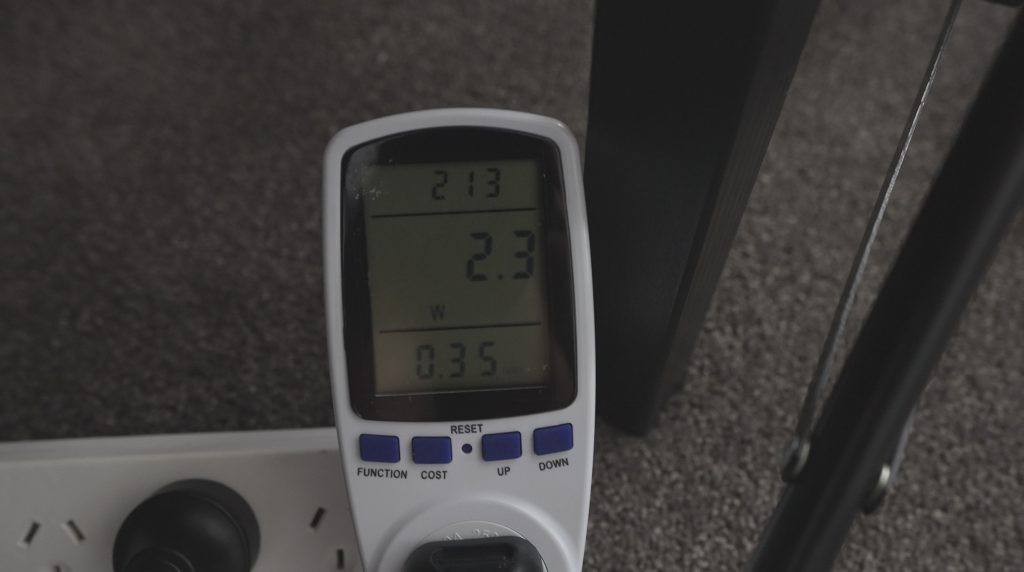
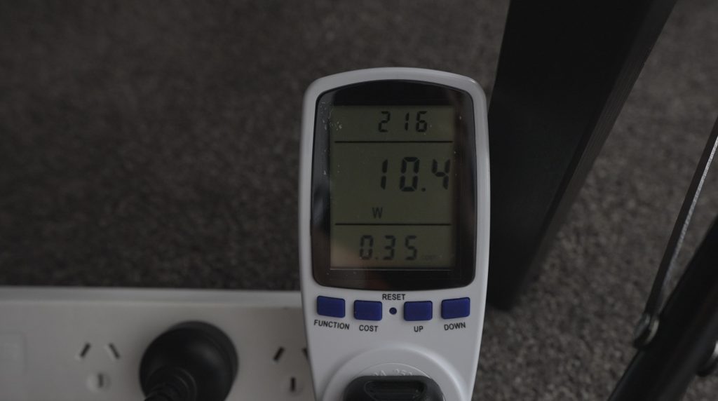
Given that we’re now using over 2000% more power just to run the fans and that most Raspberry Pi’s are not running flat out continuously, I’d say a single fan on a decent size heatsink like the Ice Tower or Ice Cube cooler is more than enough – even for overclocking.
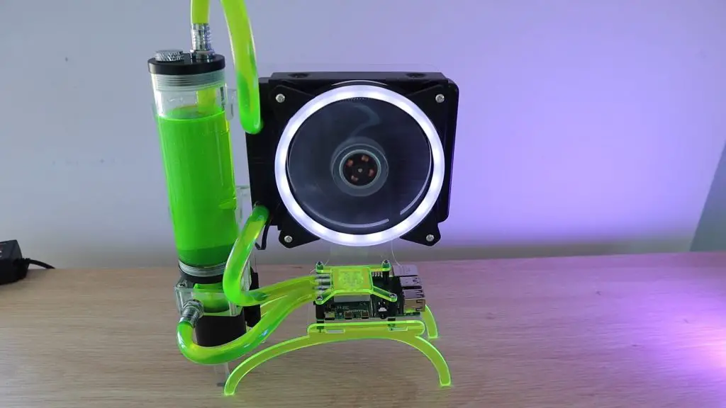
And If you’re really keen on keeping the temperature of your Raspberry Pi as low as possible, you’ll have more fun water-cooling your Pi. It’s also quieter, more power efficient and cheaper than buying 24 fans.
Let me know what you think of my fan case and let me know if there is anything else you’d like to see me try to cool my Pi with in the comments section below.


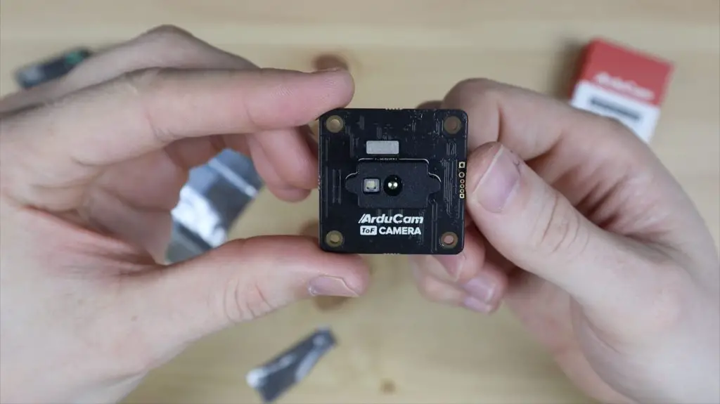
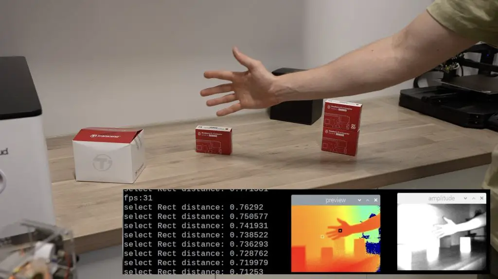
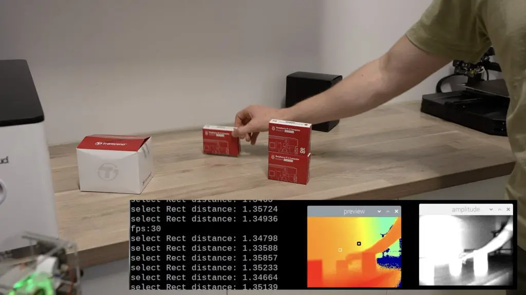
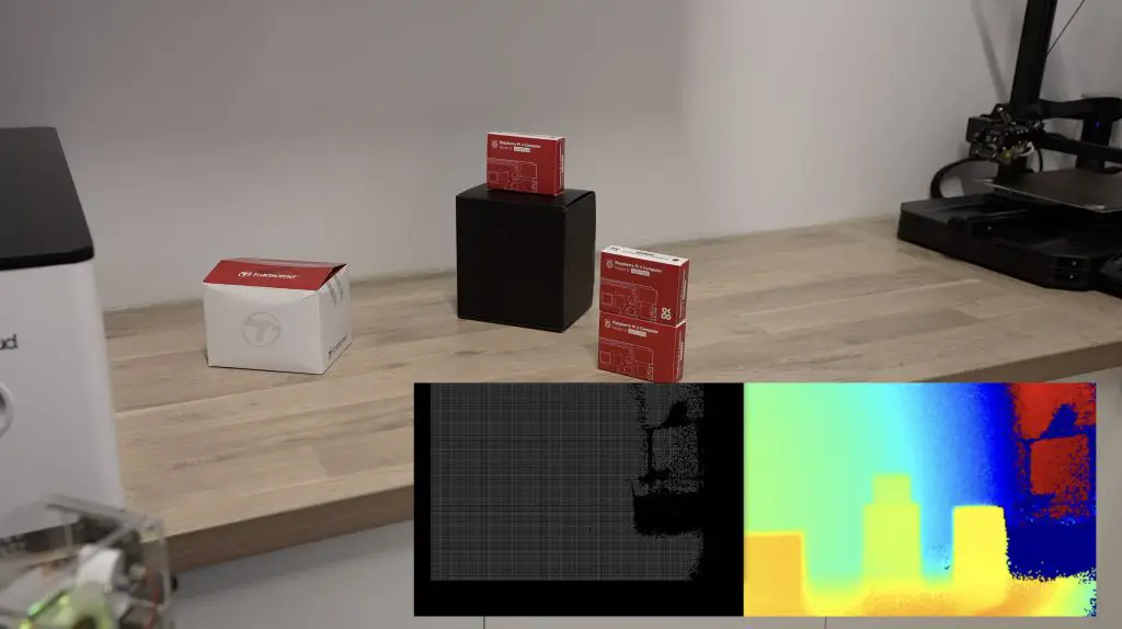
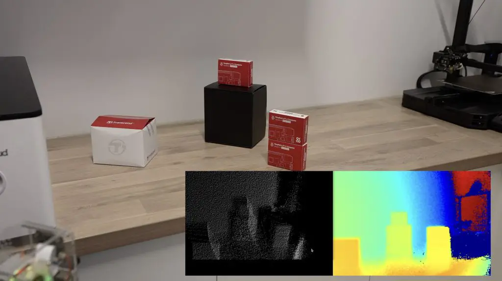
 Camera – Your Pi Can Now See In 3D")