In this project, I’ll be showing you how to make your own watch movement cufflinks using the mechanical watch movements from two old watches. There are loads of watch movement lookalike cufflinks available online, but these ones are made using real vintage watch movements taken out of an actual watch.
To start off, you’ll need to find two old mechanical movement, wind-up watches with identical mechanisms. A good place to start looking is to go down to your local watch repair shop or jeweller and ask them if they have any old movements or watches lying around. They don’t need to be working anymore, so they’ll likely be ones that the jeweller couldn’t repair and they will usually be happy to give you a few or sell them quite cheaply. You can also buy old damaged movements online from sites like e-bay.
Here’s a video of the assembly process, read on for detailed step by step instructions:
If the movements haven’t already been removed, you’ll need to take the movement, along with the face out of the watch. This is usually done through the back cover of the watch. Open up the cover and use a screw driver to pry the mechanism out. These old mechanisms are usually quite strong around the edges but be careful that you don’t scratch them.
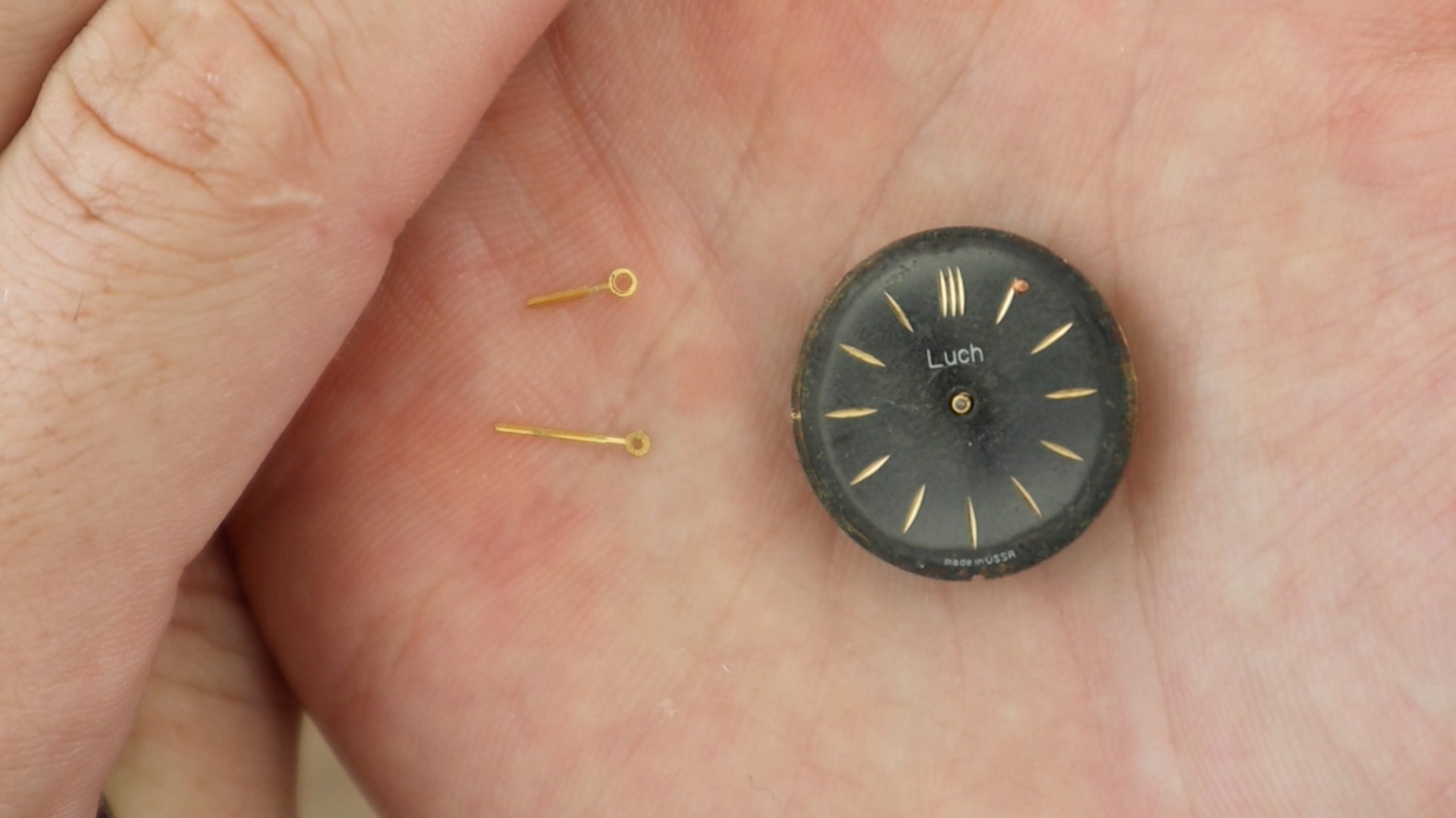
Next use a flat tipped screwdriver or tweezers to remove the hour and minute hands from the face of the watch. These usually just pop off.
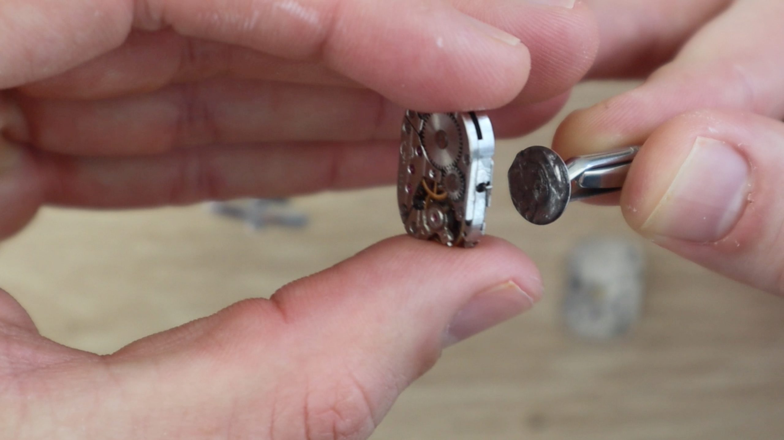
Now insert your screwdriver between the mechanism and face and gently pry the face away from the mechanism. It doesn’t really matter if you damage the face or part of the mechanism as you won’t be using the face, and this part of the mechanism is the back side of the cufflink.
Once the mechanism is free, you’ll need to make the back face flat by removing the hour hand cog and the shaft which drove the minute hand. Pry the cog off with your screwdriver or tweezers and then use side cutters or clippers to cut the shaft off flush with the back face.
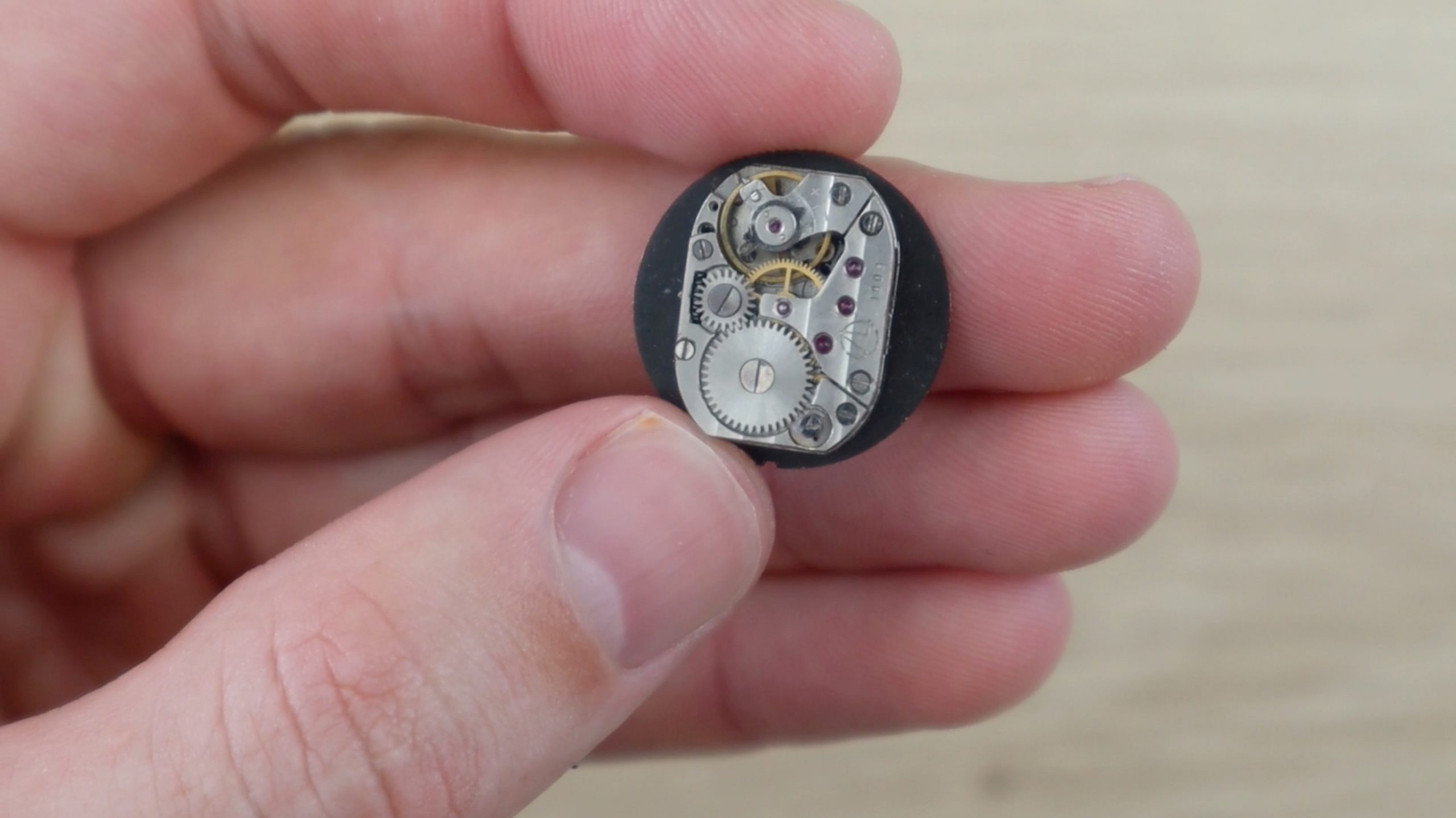
Feel the surface of the mechanism and make sure that it is completely flat so that the blank cufflink disc is able to be glued flat onto the mechanism.
Repeat this process for the second watch mechanism so that you have two identical mechanisms which are free of any protruding shafts, pegs or adjustment screws.
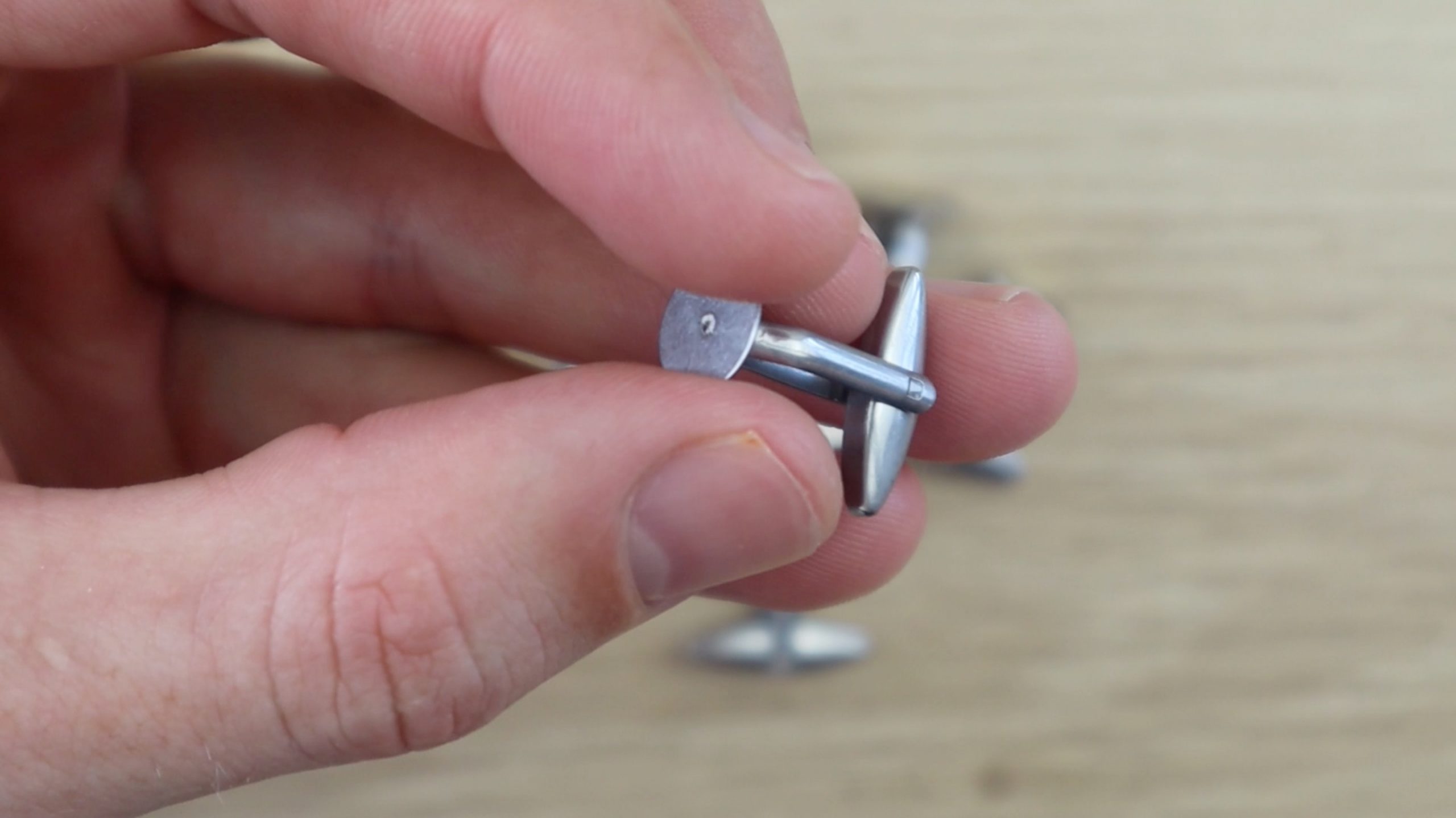
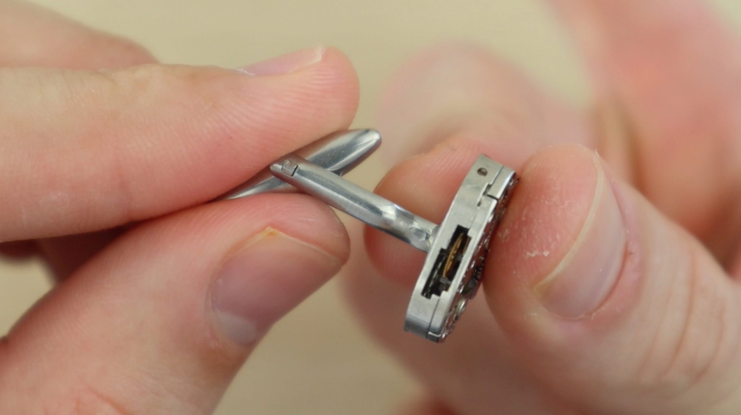
Next you’ll need to get some blank cufflinks. These are also widely available online. You’ll need a pair with at least a 6mm diameter blank plate although 10mm to 16mm ones work best to glue onto the mechanism. Try to find good quality ones and they’ll last a long time.
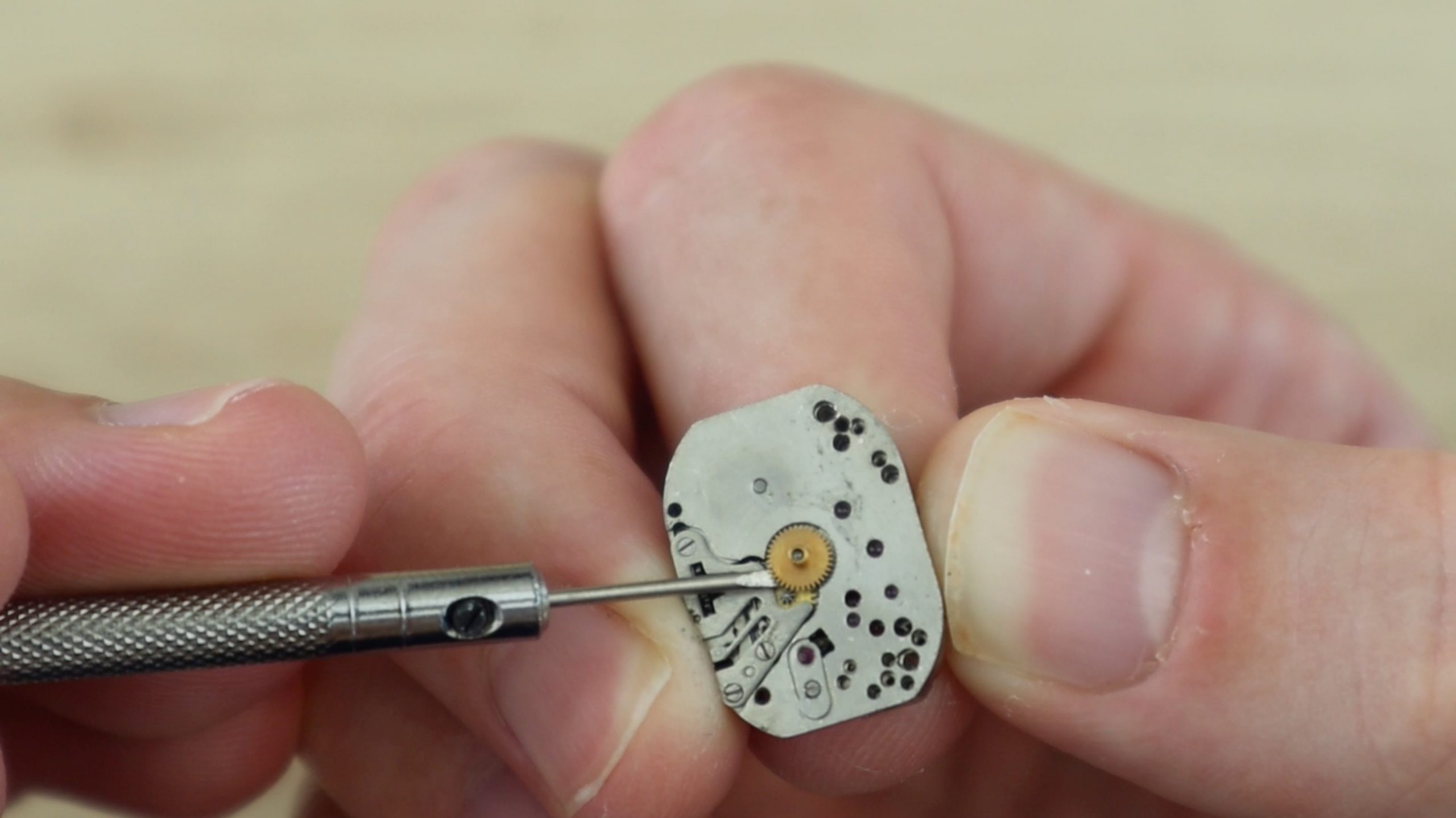
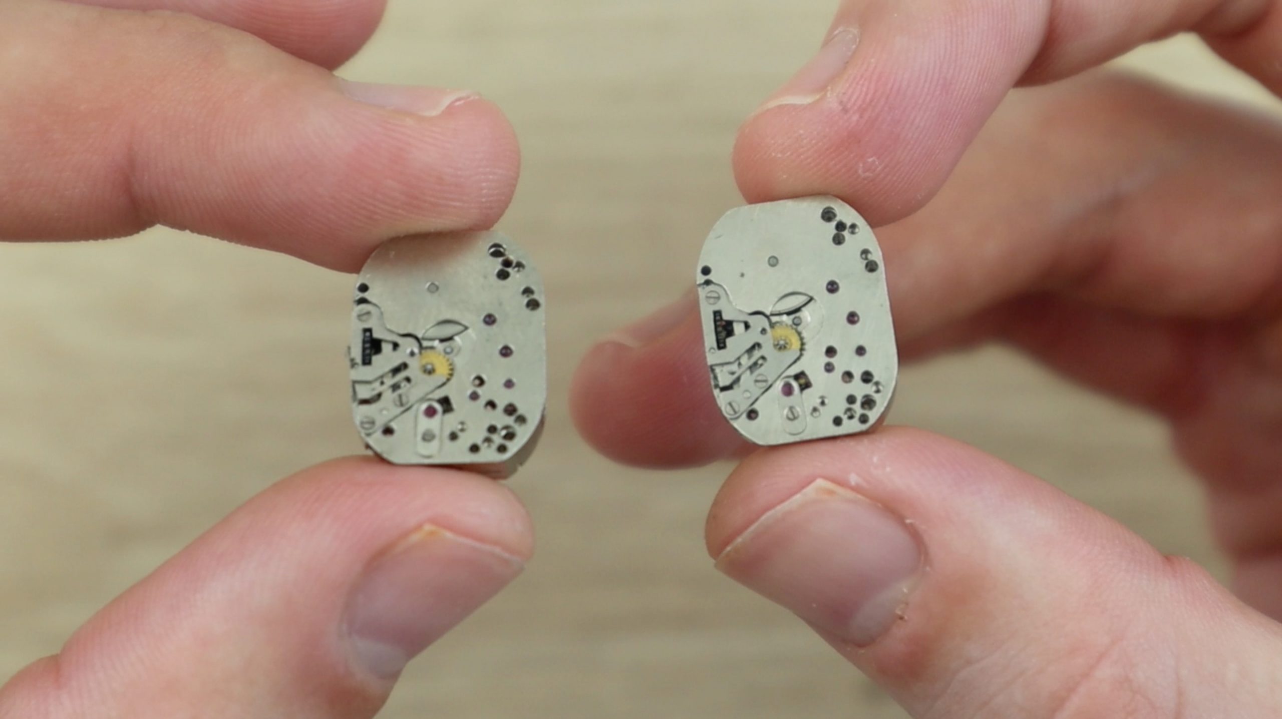
Use superglue or epoxy to glue the blank cufflink onto the back of the mechanism. Apply a generous amount of glue and make sure that you choose an unobstructed flat surface on the back of the mechanism to glue it to in order to reduce the risk of it coming off. Glue both into the same area on each mechanism and make sure that they are the same orientation.
Allow the glue to dry or cure and your cufflinks are now ready to wear.
They also make a great gift, which you can complete by putting into a small cufflink jewellery box. Small wooden boxes are great and are often able to be laser engraved to personalise them.
Modern technology has brought forth numerous benefits for various leading industries. Things such as modern machinery, artificial intelligence, the IoT, blockchain, and extended reality make huge changes in the industries they manage to penetrate.
The technology itself experienced some significant innovations and will only continue to do so. That is why every business nowadays should look for ways to implement modern technologies in their offer. Otherwise, they risk becoming entirely obsolete. So, let’s see how modern technology can improve various industrial sectors of today.
The IoT
The main idea behind the internet of things is to enable people to more easily connect to everything and everyone. As such, it is the perfect tool for businesses looking to improve their operations. For instance, the IoT can change the way products are being designed and created. Not only that but it can also greatly influence the way those products are being presented to the audience. When combined with machine learning, the IoT can help industries tailor their offers better which will increase the response and engagement those industries will receive.
Extended reality
Virtual, augmented and mixed realities are already being implemented in various industries. From the entertainment industry and education to healthcare and home improvement industry. For instance, staging showing and even pretend-decorating a home has been made significantly easier thanks to VR and AR. Nowadays, thanks to virtual reality, you can view a property from the comfort of your own home, without necessarily having to drive all the way to the property’s location. On a similar note, you can use AR to virtually equip the space with different types of furniture, which is greatly useful for interior designers and decorators around the world.
B2B online marketplaces
Since the majority of businesses from various industries have already shifted their ventures online, it comes as no surprise that B2B online marketplaces have experienced such growth in 2019. This year, we can only expect them to grow and develop further. Aside from brick and mortar commerce, industries such as the gas and oil industry will also notice huge benefits this online market will present them with. Not only will it be easier for these giants to obtain the necessary working tools, such as high-quality oilfield equipment, but they can now do so from sellers located all around the world. Online marketplaces have become seriously effective nowadays, and with the use of AI-powered shipping software and streamlined transportation tools like drones, most of the local deliveries could be performed within hours.
Recognition software
Recognition software is another piece of modern technology that found its place in various industries. Businesses dealing with security, fashion, construction and even autonomous vehicle production can greatly benefit from implementing some type of image or face recognition in their endeavor. For instance, the fashion industry embraced this trend by creating an app that recognizes outfit pieces worn by photographed individuals. Once you take and upload a picture of – let’s say – a certain pair of shoes, you can learn all the information necessary about the shoes in question, such as the manufacturer, where to buy them and how much they cost.
Blockchain
Blockchain-based currencies have been steadily gaining in popularity. That is just one of the reasons that this piece of technology will continue to rise steadily. More and more businesses will start using blockchain not just to offer their audience an alternative method of payment, but also to improve the overall security. Since blockchain is virtually impossible to hack and tamper with, it becomes quite obvious why more industries should embrace it.
Cloud computing
Cloud computing has became an integral part of a modern-day business world. Moreover, cloud computing jobs are among the most in demand tech jobs in the world. The simple fact that the cloud doesn’t need to be maintained and updated on a regular basis – at least not by its users – says a lot about this piece of modern tech. Thanks to cloud computing, businesses can nowadays group together and unify all of their business information and documents that can be easily accessible by anybody with proper authority – anywhere in the world. This, of course, eliminates the need for some other type of file and information sharing solutions. It also makes the entire process significantly faster. And since in the business world time is money, it’s understandable why so many industries choose to stop wasting it.
Drones
Finally, when they first appeared on the market, drones were mostly used for military purposes. Soon after that, they’ve become widely available and everyone could get themselves a flying, remote-operated set of eyes. Nowadays, drones are being used in various industries more than ever. Amazon, the leading online shopping giant, is working on implementing drones in their delivery services. Moreover, drones are also being used as an additional home security system. They’re also being used in the healthcare industry to deliver things to different sections of hospitals; in various warehouses not only to monitor the employees but also to ensure that everyone’s safe.
As you can see, modern technology truly has the power to bring the entire industrial sector to a whole new level. Therefore, no matter the industry you’re operating in, check out some of these pieces of modern technology and see how you can use them to better your business efforts.
I’ve always been fascinated with mechanical flip displays, like the ones used in airports, and mechanical 7 segment displays like those used in old ball game score boards. I came across a project online in which the builder had started putting together a single digit seven segment display which used solenoids controlled by an Arduino to actuate it. I have seen micro servos used in all sorts of robots and bionic arms, so I thought it would be a nice idea to try and actuate a 7 segment display using servos. The Arduino Uno, which I usually use for Arduino projects, only has 6 PWM outputs, so I had to get the Arduino Mega. The Mega has 15 PWM outputs, so it was perfect to duplicate some parts of the code and make a two digit display which could count down from 99 (or up to 99).
Here is a full guide with the Arduino code and the 3D print files to build your own mechanical 7 segment display using an Arduino Mega and 14 micro servos.
This guide assumes that you’ve worked with an Arduino micro-controller before and know the basics of programming an Arduino. If you do not, follow the linked guide for more information on creating and uploading your first sketch.
Here is a summary of the build and a video of the display in action. Continue reading for full step by step instructions along with the code and print files.
What You’ll Need To Build A Mechanical 7 Segment Display
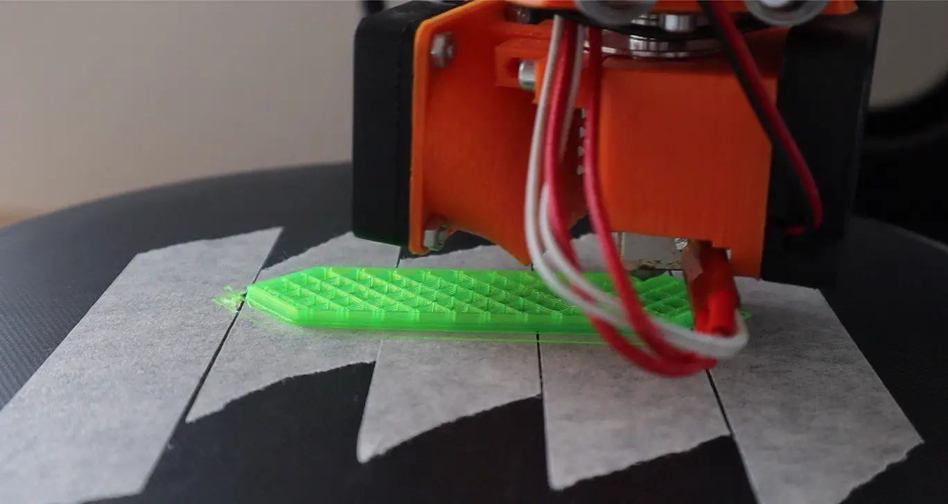
To start off, you’ll need to print the segments and mount them onto the servos. The segment is identical on all servos, so you’ll need to print out 14 of them.
I measured up the servo arms to design a segment which could be glued directly onto these arms without requiring any other hardware.
I then 3D printed the 14 segments using translucent green PLA at 185C with an infill of 15%. This did lead to the fill pattern being visible through the segments in operation. I don’t mind this look but if you want them to look more solid then either use a solid coloured PLA or print them with 100% infill.
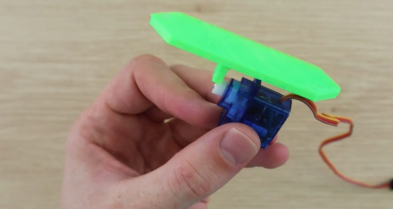
I started off by printing a single segment to check that it fitted the servo and to have a look at how it operated (that it was light enough) once glued to the servo. The segment was glued onto the servo arm using hot melt glue, epoxy will also work.
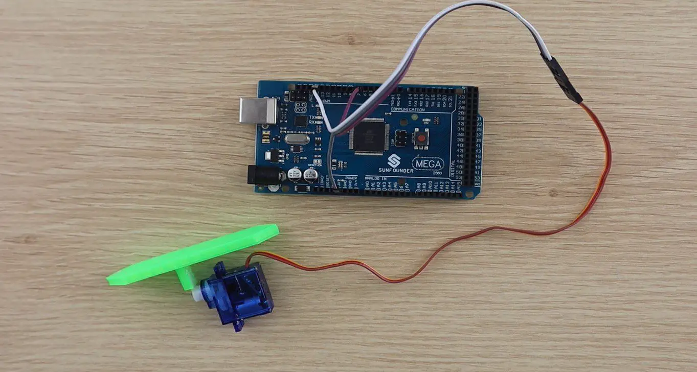
Try to align the segments so that they stand flat when the servo is square on its base. I connected the single segment and servo to the Arduino to check it’s operation.
During this test, I saw that the edges of the segments would be quite visible even when they’re turned through 90 degrees, so I’d need to colour of the side of the segment to blend in with the back board. I decided to spray the back and sides of all of the segments in black to match the back board.
There is now a significant difference between the top face and the sides of each segment.
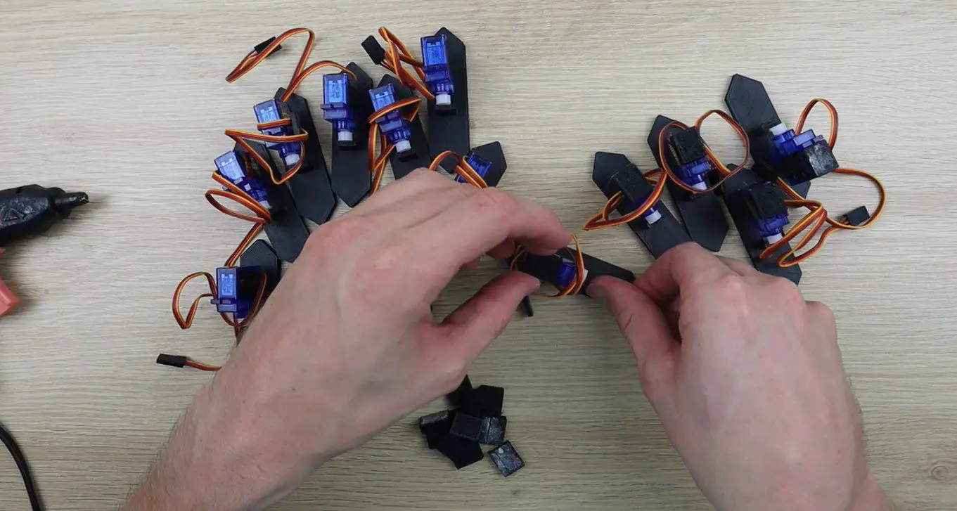
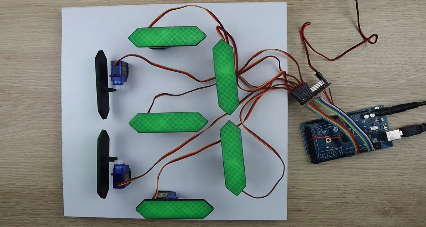
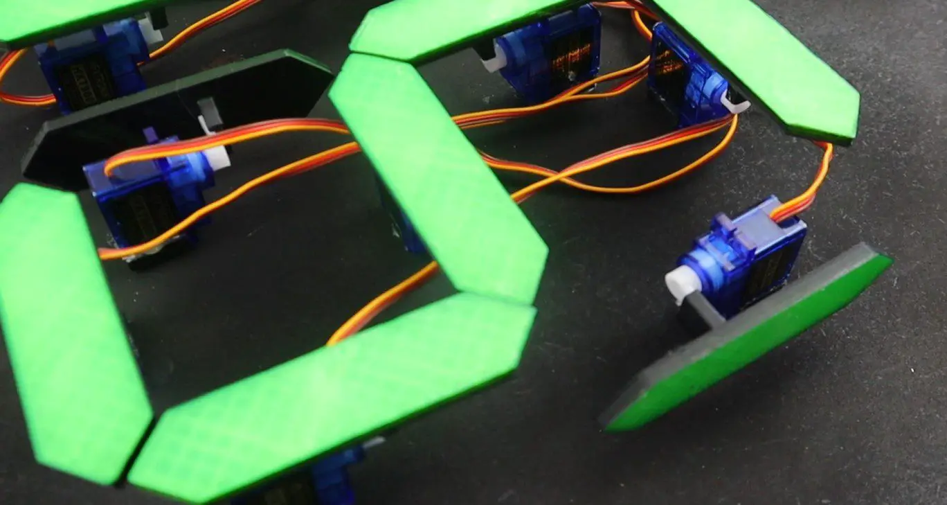
Once I was happy with the segments, I glued them all onto the servos and added a small spacer block to each servo so that they are able to stand upright.
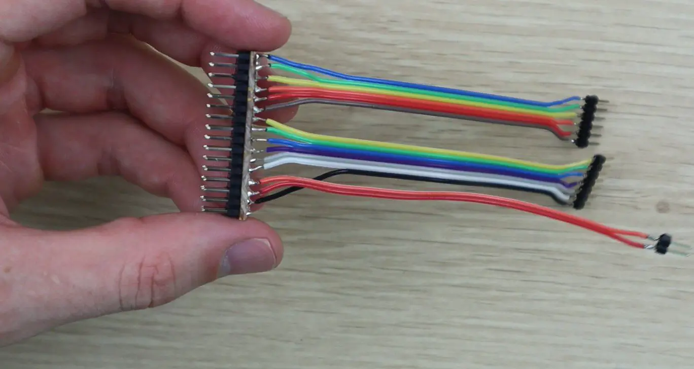
I then mapped out which segments would be connected to which pins on the Arduino Mega so that I could build the wiring harness.
There are 12 PWM inputs sequentially from 2 to 13 and I then had to use pins 44 and 45 as additional PWM pins for the last two segments.
The Arduino Mega cannot supply enough power to all fourteen servos, so I used a battery elimination circuit module made for RC aircraft to supply power to them and the Arduino to drive the IO pins. There is a closed look at the strip board and pins in the video but essentially the strip board supplies the GND and 5V pins from the BEC and then connects the GND and all of the PWM pins to the Arduino.
After I built the wiring harness, I decided to test build a single digit in order to test the code. I laid the servos out in the configuration in which they would be used and then got the code working.
During this step I had to add a few lines to the code to move the segments adjacent to the middle segment out of the way when it way moving up or down so that they wouldn’t bump into them.
Once I was happy with this digit, I duplicated the code for two digits and then mounted the servos onto a black back board.
Upload The Sketch
This is the final version of the code, the code makes use of the servo library and relies heavily on arrays to store the calibration values and movements of the servos. There is a link to download the code provided after the code.
//Michael Klements
//The DIY Life
//8 February 2020

#include <Servo.h>

Servo myservo[14];

int segmentOn[14] = {90,88,81,80,90,78,98,90,88,65,75,90,78,98};      //Servo on position values for each servo
int segmentOff[14] = {0,0,180,180,0,180,0,0,0,155,180,0,180,0};       //Servo off position values for each servo
int digits[10][7] = {{1,1,1,1,1,1,0},{0,1,1,0,0,0,0},{1,1,0,1,1,0,1},{1,1,1,1,0,0,1},{0,1,1,0,0,1,1},{1,0,1,1,0,1,1},{1,0,1,1,1,1,1},{1,1,1,0,0,1,0},{1,1,1,1,1,1,1},{1,1,1,1,0,1,1}}; //Position values for each digit

void setup()
{
  myservo[0].attach(2);   //Assign all of the output pins
  myservo[1].attach(3);
  myservo[2].attach(4);
  myservo[3].attach(5);
  myservo[4].attach(6);
  myservo[5].attach(7);
  myservo[6].attach(8);
  myservo[7].attach(9);
  myservo[8].attach(10);
  myservo[9].attach(11);
  myservo[10].attach(12);
  myservo[11].attach(13);
  myservo[12].attach(44);
  myservo[13].attach(45);
  for(int i=0 ; i<=13 ; i++)    //Set all of the servos to on or up (88 displayed)
  {
    myservo[i].write(segmentOn[i]);
  }
  delay(5000);
}

void loop()
{
  for (int g=9 ; g>=0 ; g--)    //Large loop counter to count the tens
  {
    int mustDelay1 = 0;
    if(digits[g][6]!=digits[g+1][6])  //Logic to move segments next to middle segment out of the way
    {
      if(digits[g+1][1]==1)
      {
        myservo[8].write(segmentOn[8]-30);
        mustDelay1 = 1;
      }
      if(digits[g+1][5]==1)
      {
        myservo[12].write(segmentOn[12]+30);
        mustDelay1 = 1;
      }
    }
    if(g==9)
    {
      myservo[8].write(segmentOn[8]-30);
      myservo[12].write(segmentOn[12]+30);
    }
    if(mustDelay1==1)
      delay(200);
    for (int h=6 ; h>=0 ; h--)    //Small loop counter to move individual segments  to make up the tens digit
    {
      if(digits[g][h]==1)
        myservo[h+7].write(segmentOn[h+7]);
      else
        myservo[h+7].write(segmentOff[h+7]);
      if(h==6)
        delay(200);
    }
    for (int i=9 ; i>=0 ; i--)   //Large loop counter to count the units
    {
      int mustDelay2 = 0;
      if(digits[i][6]!=digits[i+1][6])  //Logic to move segments next to middle segment out of the way
      {
        if(digits[i+1][1]==1)
        {
          myservo[1].write(segmentOn[1]-30);
          mustDelay2 = 1;
        }
        if(digits[i+1][5]==1)
        {
          myservo[5].write(segmentOn[5]+30);
          mustDelay2 = 1;
        }
      }
      if(i==9)
      {
        myservo[1].write(segmentOn[1]-30);
        myservo[5].write(segmentOn[5]+30);
      }
      if(mustDelay2==1)
        delay(200);
      for (int j=6 ; j>=0 ; j--)  //Small loop counter to move individual segments  to make up the unit digit
      {
        if(digits[i][j]==1)
          myservo[j].write(segmentOn[j]);
        else
          myservo[j].write(segmentOff[j]);
        if(j==6)
          delay(200);
      }
      if(mustDelay2==1)   //Delay logic to reduce delay if the side segments moved (adding an additional 200ms delay)
        delay(600);
      else
        delay(800);     //Delay between digits. 200ms delay already experienced in the code
    }
  }
  delay (2000);   //Delay after countdown to 0 before resetting
}
This is a high level breakdown of what happens in the code:
I initialise an array of 14 servo objects called myServo, these numbers correspond to the numerical sequence in the pin number diagram.
I then initialise three arrays of numbers. The first, called segment On, stores the on or up positions for each of the 14 servos as a sort of calibration to ensure that they are all perfectly vertical. The second, called segment Off, is the same but for the 90 degree off position. Some of these are 0 and some 180 depending on which direction the servo needs to move. The last is a 2D digit array which stores the segment positions for each digit from 0 to 9, where 1 is on or visible and 0 is 90 degrees or invisible.
In the setup code, the 14 servos are assigned to the correct pins and then a loop sets them all to on, the number 88 will be displayed. The code then waits 5 seconds before starting the countdown.
The countdown is done with four loops. An outer loop controlling the tens and an inner loop controlling the units. In each of these loops, a smaller loop cycles through the seven segments and sets them to the correct position, on or off, by looking up the value in the digit array.
The other logic in this section is purely to move the two segments adjacent to the middle segment out of the way by 30 degrees when this segment moves so that it doesn’t bump into it. This includes all of the mustDelay variables, the 200ms delays and the if statements which aren’t in the smaller loops.
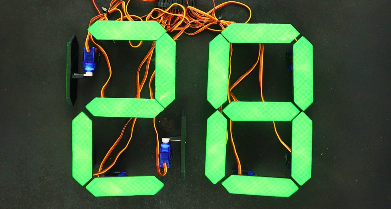
Running The Mechanical 7 Segment Display
Upload your code to your Arduino and your display will be ready to run. It will automatically reset to 88, wait 5 seconds and then start to count down from 99 to 00. When it reaches 00 it will wait 2 seconds and then reset and start counting again.
You can change the number it counts down from by setting the counter in the outer loop g. You will always need to counter from the number 9 in the units digit (i) else each pass it will miss the digits higher than the number it is set to with the code in the way it is currently written. You can’t, for example, set 47 as the starting point, it will need to be 49. If you change it to 47 then it will go down 41, 40, 37, 36 etc.
Here are some pictures of the display in operation. The video has some good footage of the display in operation.
Have you tried to build your own mechanical 7 segment display? What did you use to actuate and control it and how did it work? Let us know in the comments section below.
We realise that not everyone has the time or money to tackle a big home renovation project, but most people can free up a weekend for a smaller project or two to add value to their home. Here are 10 easy and manageable home improvement projects to plan for a free weekend to really get your home looking great again.
Deep Clean Your Driveway and Pathways
When was the last time you gave your brick or cobblestone pathways a clean? This is something not many people give any thought to and it can actually be quite effective in making your home look newer and cleaner. Sidewalks, driveways and pathways slowly become stained by wet leaves, moss, mildew, dirt and leaks from your vehicles. Either buy or rent a power washer and give your pathways a deep clean, it doesn’t take a long time to do and you’re sure to be impressed with the results.
Wash The Outside Of Your Home
Remember how good your home looked when you first painted it? If you used a good quality paint then chances are that the paint still looks good a few years later, it’s just covered with dust and dirt. Use the same pressure washer you used in the previous tip to give the outside of your home a proper clean. You shouldn’t even need a ladder, the powerful jet will have no problem washing the built up dust and dirt from your walls, leaving your home look freshly painted again.
Make sure that you test it out on a small patch first to ensure that the paint is still well adhered to the underlying surface and won’t flake off.
Revive An Old Room With A Coat Of Paint, One Of The Most Effective Ideas For Home Improvement
As far as home improvement goes, few things can transform a room as effectively as a fresh coat of paint. Repainting a room with a bright and modern colour can really go a long way towards making it look like it has been completely transformed.
If you don’t have the time or money to paint the whole room, consider painting just a single accent wall. Choose a colour to compliment your room’s decor. Don’t choose a colour which is too dark as you’ll have to spend a lot of time and money if in future you decide to cover it up or go back to a lighter or more neutral colour.
Install A Modern Programmable Thermostat
If your home still has an old fashioned dial thermostat, then its definitely time for an upgrade. Installing a programmable thermostat may cost a bit initially but you’ll save a lot of money month to month. Modern thermostats are much more effective at regulating your homes temperature and have the potential to vary your homes temperature throughout the day and while you’re not at home in order to save energy. Here are some other ways in which to drastically reduce your home’s energy consumption and save on your electrical bill.
Deep Clean Your Carpets and Furniture
Get the family together for a day to help you move the furniture and rent a carpet shampooer to give your carpets, sofa and upholstery on your chairs a deep clean. Once you’ve moved the furniture, it shouldn’t take you more than 15 to 20 minutes to shampoo the carpets, so you could get through your whole home in a morning. You’ll be surprised by how much brighter your carpets look and how much dirt is sucked up in the water.
Upgrade Your Cabinet Hardware
Replacing your cabinet hardware is a great way to update your kitchen and bathrooms without spending a fortune. It usually requires nothing more than a screwdriver if your choose new hardware with the same mounting holes. If you’re replacing simple knobs with proper handles then you’ll need to drill an extra hole each and it saves time building a template first to make sure that all of your new handles are straight and in the same position.
Replacing the hinges also makes a big difference. Old hinges tend to sag and don’t offer as many adjustment opportunities as modern hinges. You’ll get all of your cabinet doors straight, aligned and not bumping into each other in no time. Here are some tips on getting your cabinet hinges properly adjusted.
Change Your Kitchen Or Bathroom Faucets
Old faucets not only look unattractive with a buildup of years of grime and mildew but also often drip or leak. Swap out your old faucet for a stylish and modern new design with an aerator, you’ll not only add visual appeal to the room but also save money on your water bill in the long run.
Upgrade Your Light Switches & Outlets
Replace your boring old beige light switches and cover plates with something more modern and decorative. Modern switches and outlets come in a wide range of designs and colours and often include additional features such as built in USB chargers.
If replacing your outlets and switches seems too expensive, you could also just remove the cover plates and give them a fresh spray of paint.
Add Smart Lighting To Your Next Home Improvement Project
Nothing says designer home quite like soft and warm lighting. Smart lighting systems used to cost a fortune and involved a big home improvement project, requiring your whole electrical system to be rewired, but simple modern smart bulbs have completely changed the way in which you are able to control the lighting in your home. Get yourself a smart lighting system, like the Philips Hue starter set and you’ll be amazed at how effective an adjustable lighting solution can be at making your home look more designer. You’ll also be able to impress your family and friends by having your lights turn on and off automatically, have them voice controlled by your Amazon Echo or control them with your mobile phone.
There is a wide rang of smart indoor and outdoor globes and light fixtures for you to completely transform your home’s lighting.
Beat The Squeaks
A house sounds old and un-maintained if the doors squeak when you open and close them or the floorboards squeak when you walk on them. Restore the peace and quite in your home by giving your door hinges an oil with a quick spray of WD-40 and stop the squeak in your floorboards by sprinkling talcum powder over the problem areas and sweeping it into the cracks.
Have you tried any of these home improvement projects? Let us know in the comments section below. We would love to hear your tips, tricks and ideas.
In browsing through Wish for some electrical components for upcoming projects, I stumbled upon this DIY Tesla Coil kit advertised for $5. I’ve seen them online before on EBay and Aliexpress etc. but never given them much thought. But for $5, I thought I’d try one out. This was my first kit-form electronics project I’ve bought and while it presented a few challenges, it was relatively easy to get working and the quality of the components wasn’t too bad.
Here’s a video of the build and testing, read on for the write up.
What Was Delivered
I ordered the Tesla coil kit early in January. It took and about two weeks to be delivered, which wasn’t too long a wait but is certainly a lot longer than local products from Amazon or EBay.
Here is the link to the kit from Wish and an equivalent from Amazon if you don’t want to wait for it:
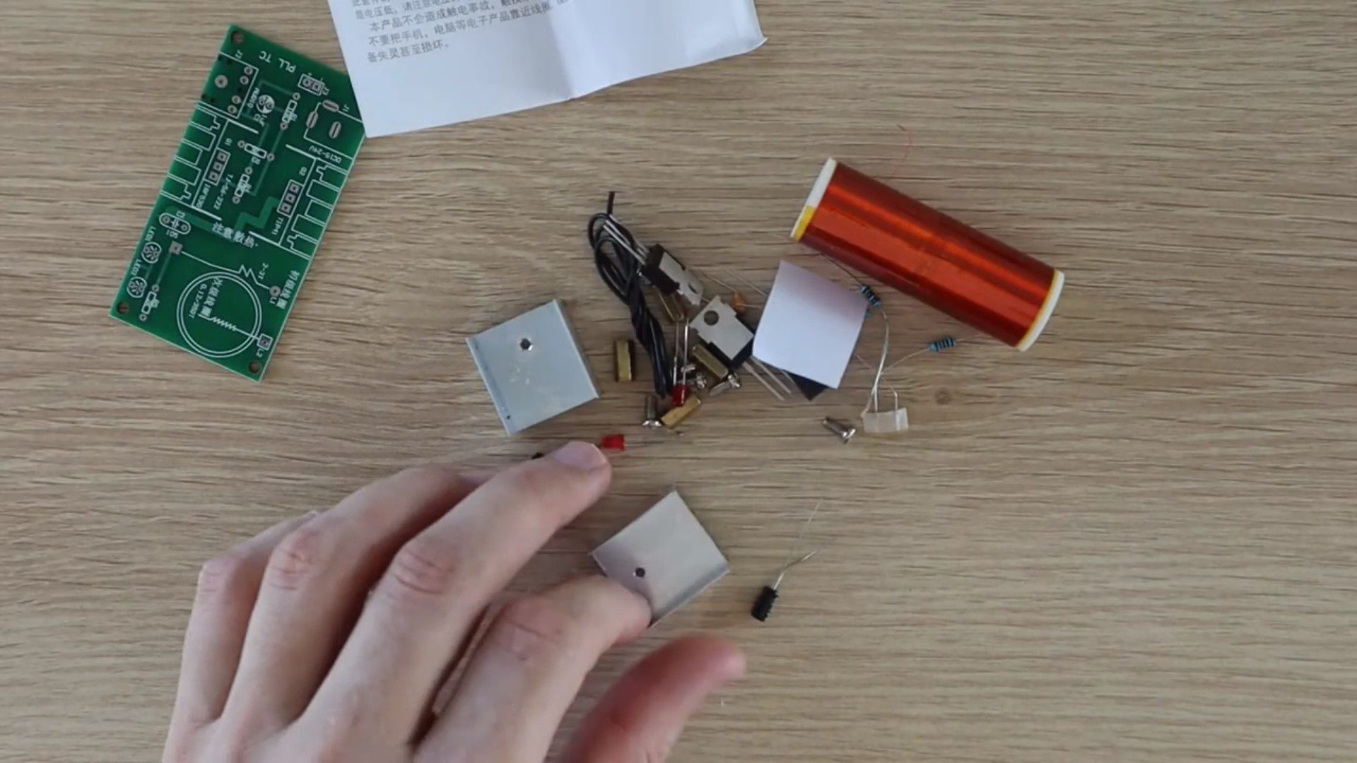
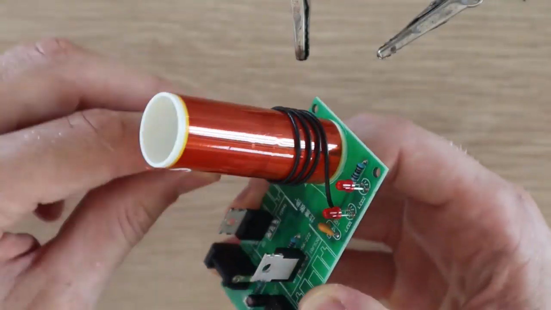
The kit came pretty well packaged in bubble wrap and included the components as shown below.
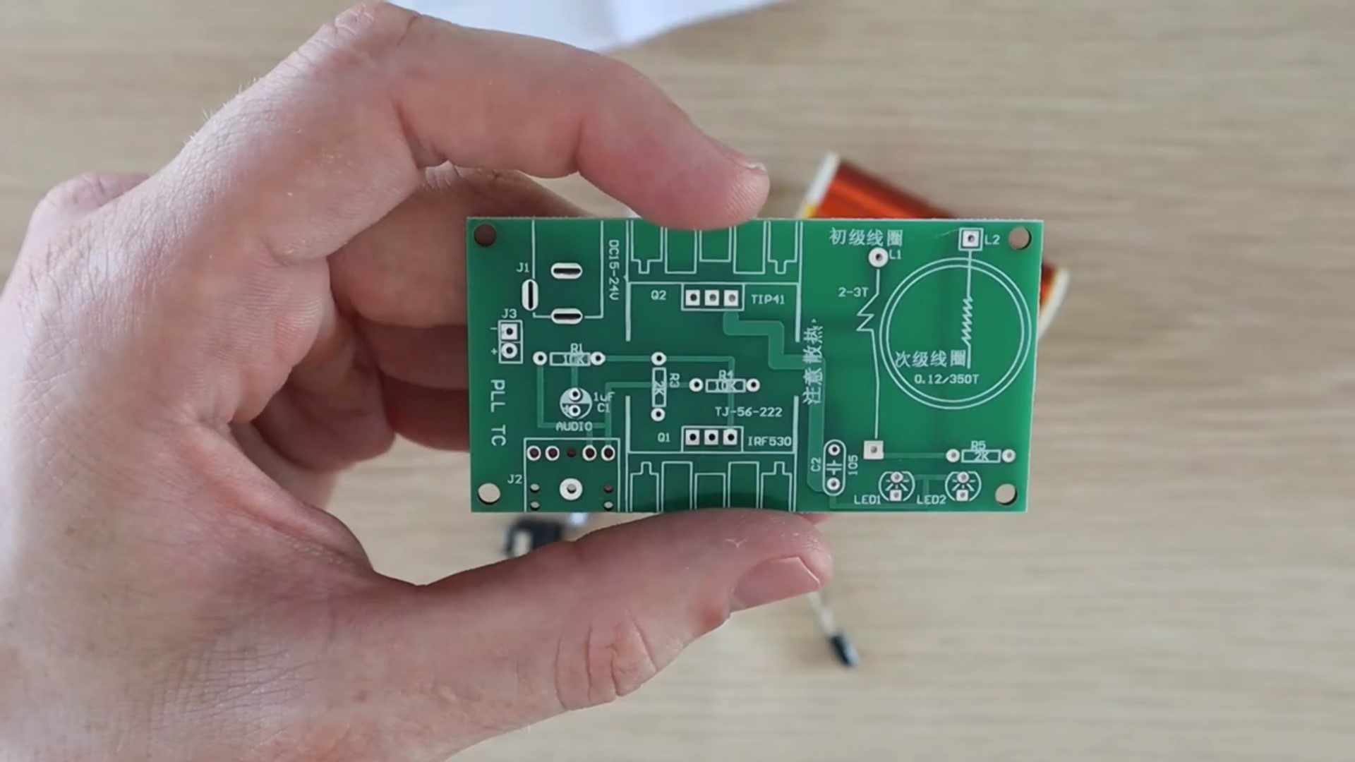
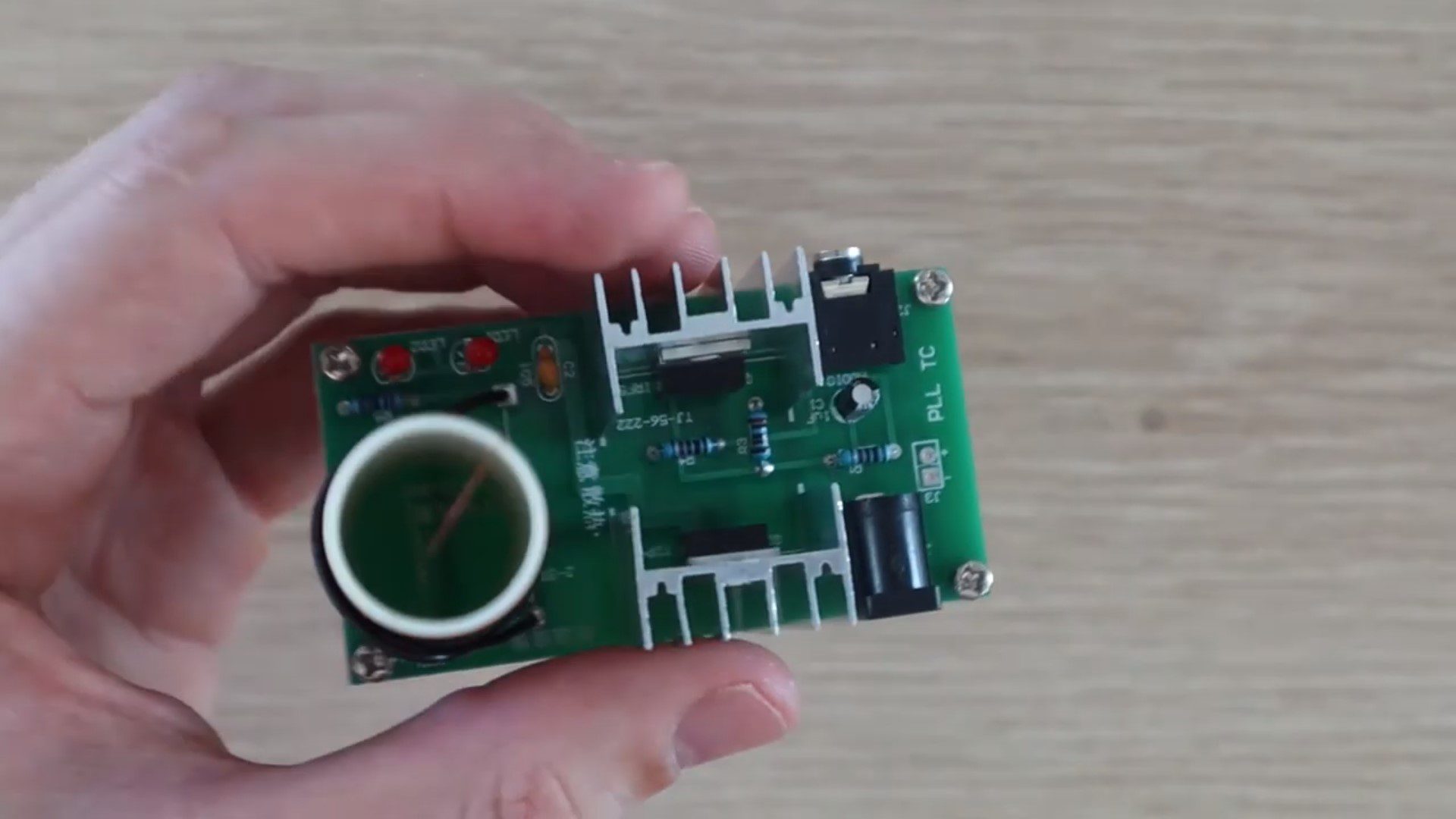
The PCB is pretty good quality and has all of the component locations clearly identified and component references marked. I didn’t have any issues with getting the components assembled onto the board.
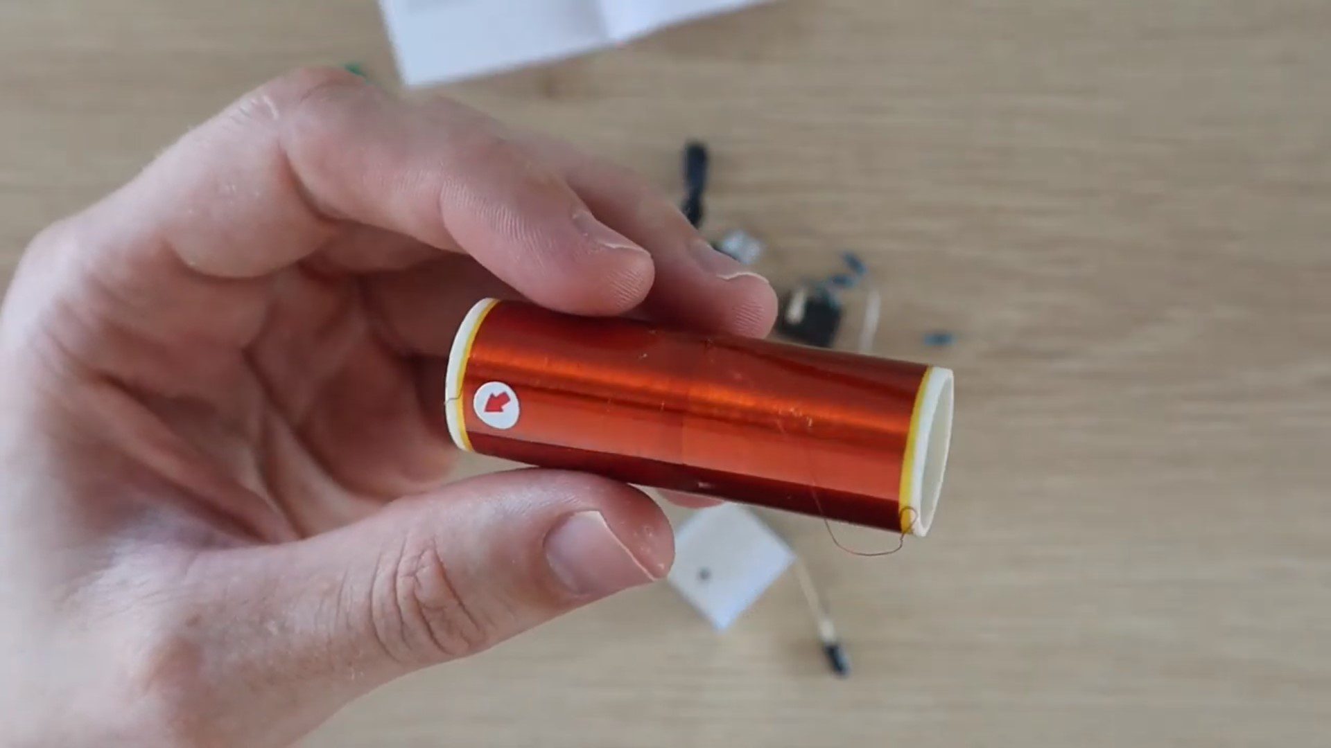
The secondary coil came pre-wound. I know that this should be the case, but with products from Wish, you never know just how much DIY work may be involved in assembling them.
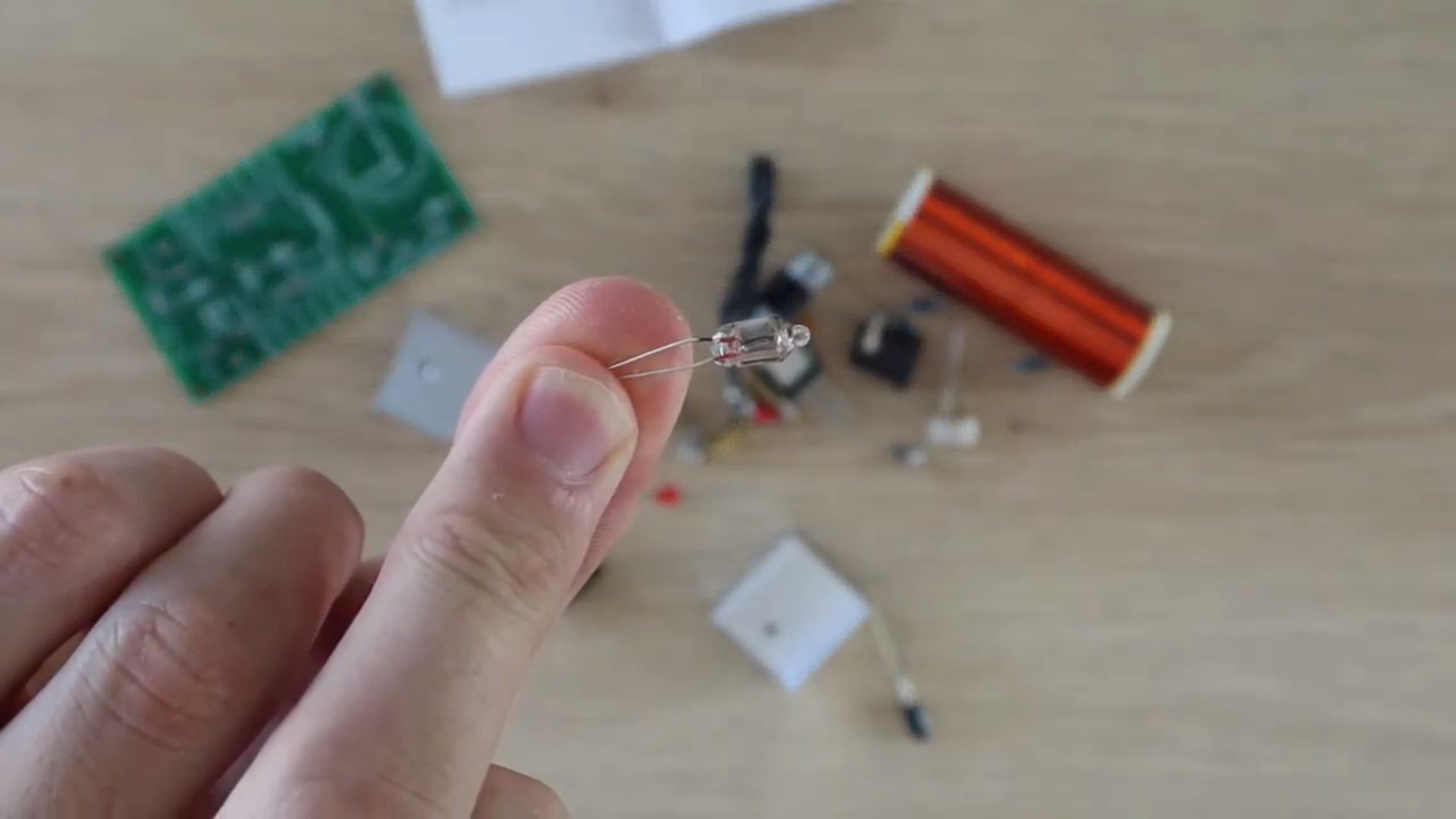
Lastly, they included a small light bulb to test the Tesla coil kit with.
The kit included an instruction sheet. Again, coming from Wish, this is not always the case. The trouble with the instruction sheet is that it was all in Chinese. It’s not an overly complex build and the components are all identified on the PCB, but I had no idea what the supply voltage was, how to assemble the primary coil or if there was anything else to look out for during the assembly process.
I landed up using Google Translate on my phone to translate most of the sheet into English. It wasn’t the greatest translation and included a few questionable lines about fire and electric shocks, but I managed to figure out that the supply voltage should be in the range of 9V to 30V and that anything above 15V provides the best results. I also found a line which mentioned something about a common problem being that the primary coil is wound in the wrong direction but couldn’t find anything about what the correct direction is.
Assembling The Components
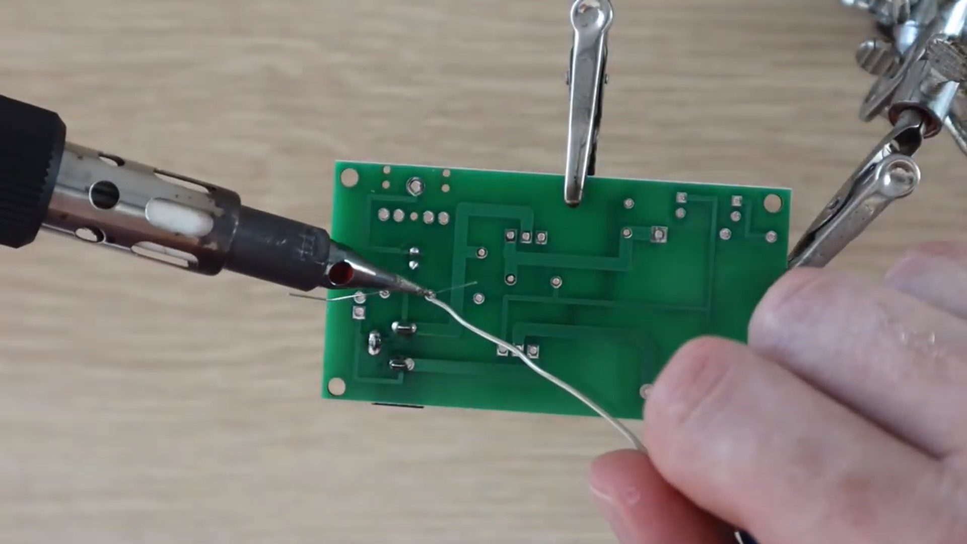
Once I was fairly happy with what to do, I began soldering the components onto the PCB. There isn’t really anything tricky involved (other than the primary coil). I soldered all of the components onto the board, then glued the secondary coil in place.
I then had to wind the primary coil. I started off by winding the coil as shown below. I figured out after switching it on, and having nothing happen, that this was obviously the wrong direction which they mentioned in the instruction sheet. So I had to remove it and remake it in the other direction. Also, although I wound it tightly to make up the coil shape, I then loosened it as the coil should be loose when soldered in place and there should be a gap between the primary coil leads and the secondary coil otherwise it also won’t work.
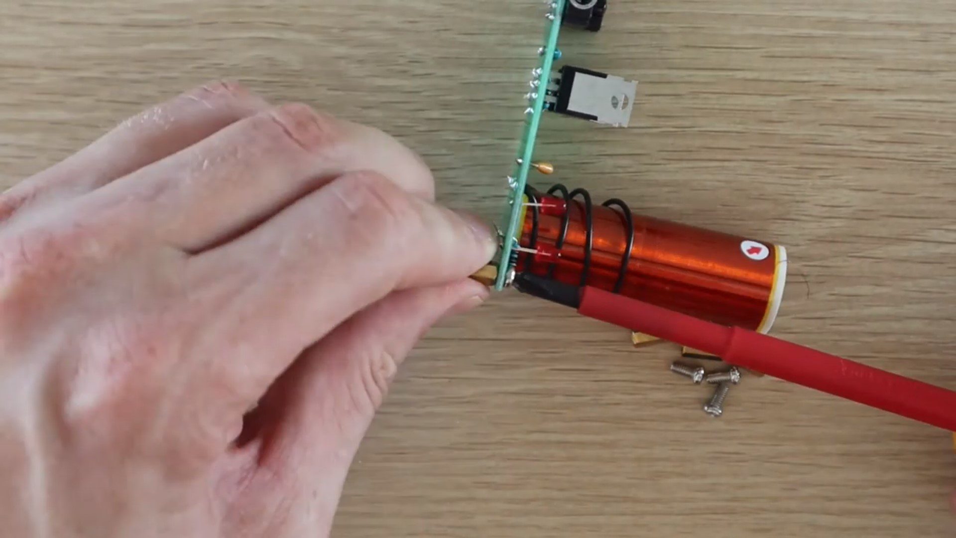
I then finished it off by adding the screw on legs and the heat sinks. I stuck the heat sinks on with my own thermal tape rather than the included screws.
This was the final, fully assembled Tesla coil kit.
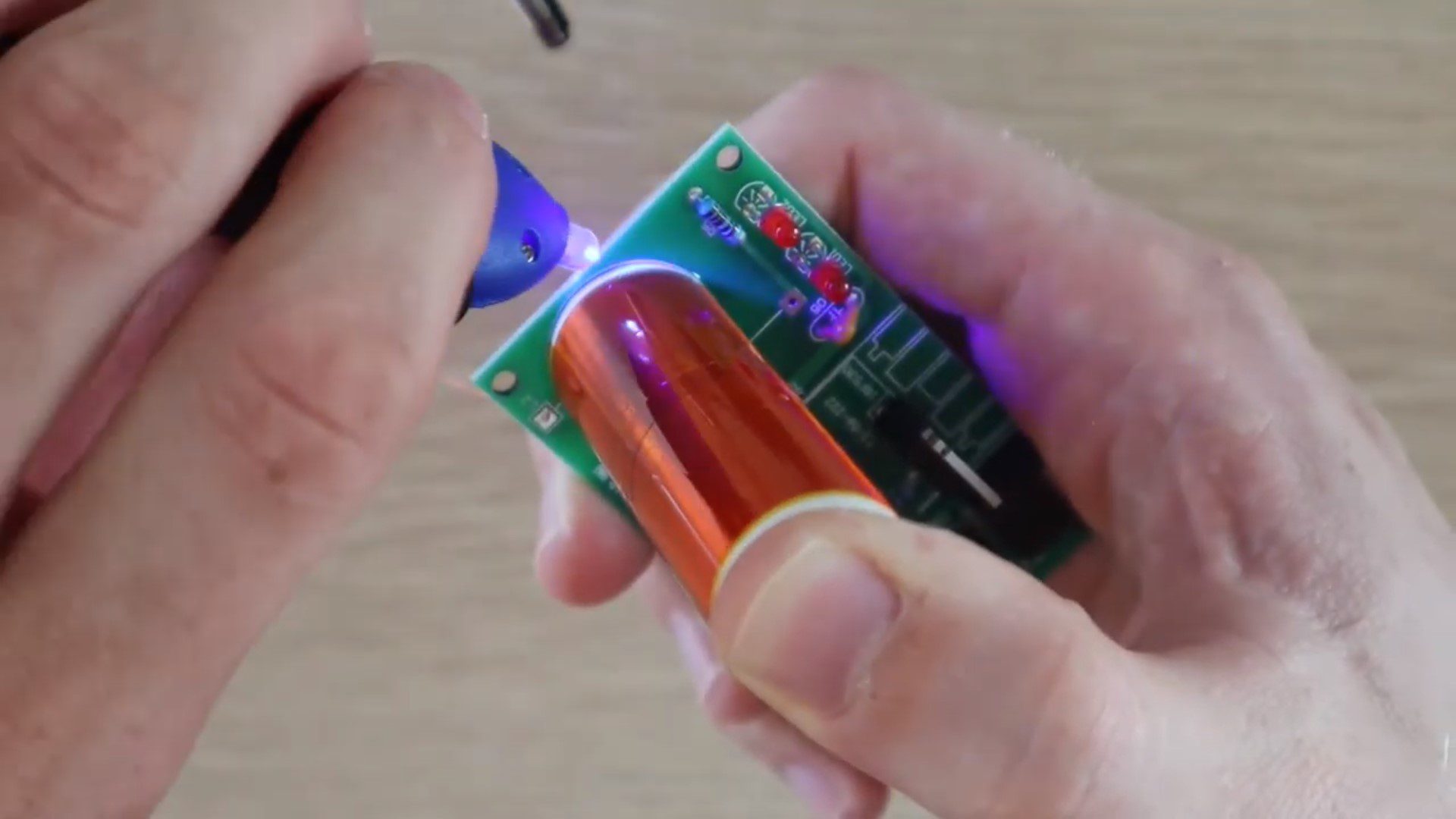
Testing The Mini Tesla Coil Kit
As I mentioned before, the first time I powered it on, the LED came on but nothing else happened and the light bulb wouldn’t light up near the coil. I figured that this may have something to do with the primary coil as they had mentioned that this was a common problem in the instructions. I switched the coil direction around and it then worked perfectly.
I only have a 15V power supply, but this was enough to generate a high voltage discharge on the end of the secondary coil.
The included light bulb lights up really well around the Tesla coil, even from a few centimetres away.
I then played around with creating an arc between the tip of a screwdriver and the end of the coil. I also had some fun with the arc, burning the remaining plastic coating (insulation) off of the secondary coil wire.
Overall, I really enjoyed building this little kit and had some fun playing around with it. Its a great starter electronics kit with larger components which are easy to solder. I’m sure that there’s a pretty high success rate with these, there really isn’t too much which can go wrong – aside from with the primary coil. So if you’re keen to build your own Tesla coil, have a look at the kits in the links above.
Have you assembled an electronics kit which you’ve bought online? Let me know in the comments section below. Also let me know if you have any other suggested kits to try out.
You may not be aware of this, but your iPhone may be keeping a detailed list of locations which you frequently visit, and some which I’ve only visited once or twice. It also stores a surprisingly creepy amount of detail for each visit including the dates, times and duration of your visits, the address and GPS co-ordinates of the location and even details on which mode of transportation you take to get there.
According to Apple, this feature is used to learn which places are significant to you and it uses this information to provide suggestions on transport options and places which may be of interest to you. They also claim that the list of locations information is encrypted, stored only on your device and is not used without your consent. Apple isn’t the only one keeping track of your location information, the majority of smartphones make use of this information in some form. Google, for example, does this too, you can access a location history list through your Google account.
Here’s How To See List Of Locations Which Your iPhone Is Storing
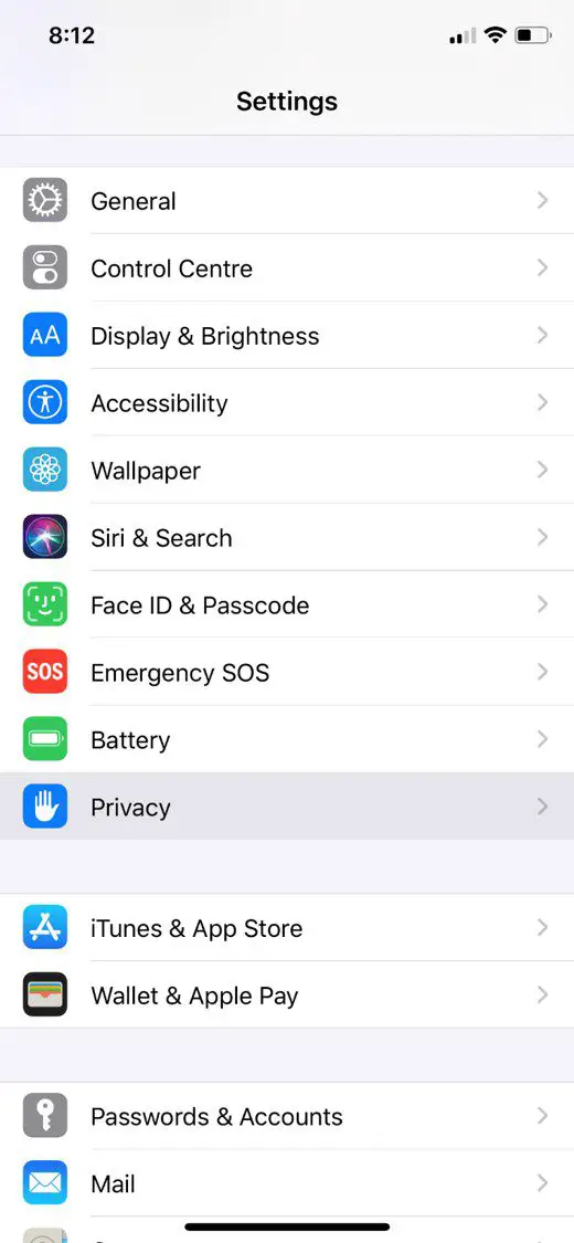
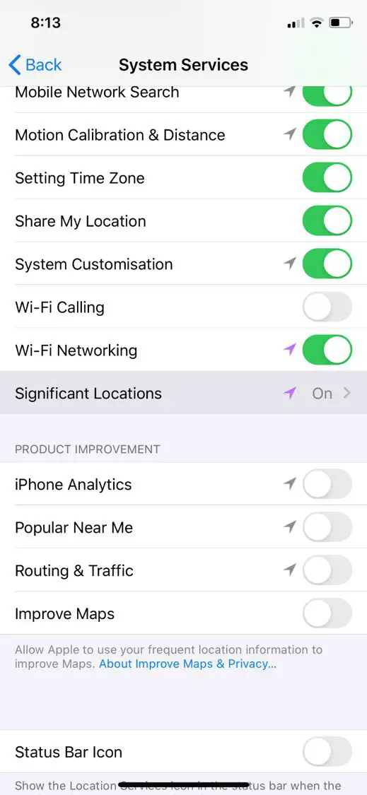
Open up your Settings app and then head down to Privacy.
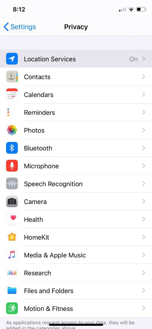
Open up the first option, Location Services.
Here’s you’ll see a list of which apps are allowed access to your device’s location and when. Scroll down to the bottom and select System Services.
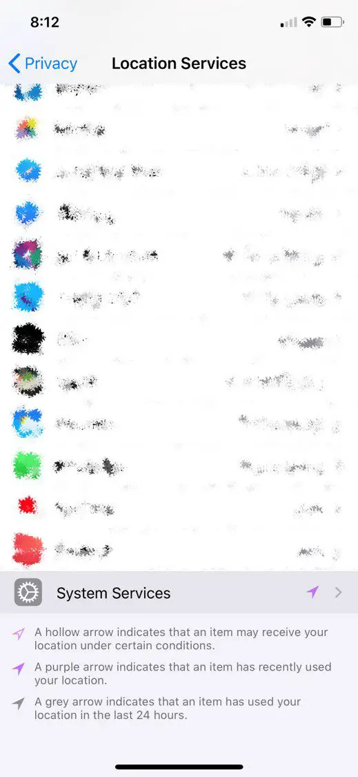
Now you’ll see a list of system related functions which have access to your location and an arrow showing you when last the service accessed your location information. Scroll down to the bottom of this list and select Significant Locations.
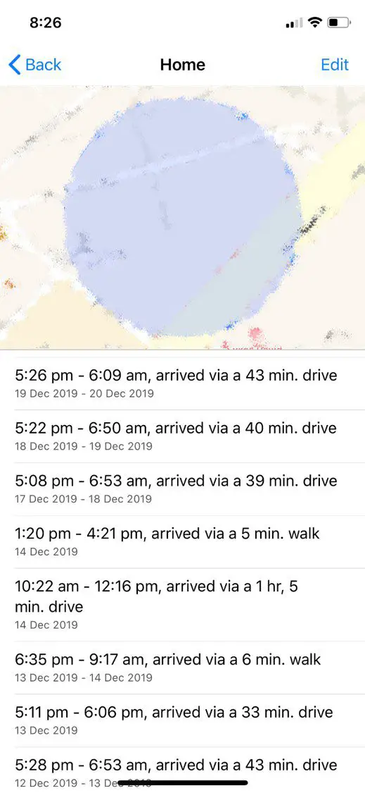
You’ll now see a pretty comprehensive list of everywhere your iPhone has recently been, organised by city.
You can open up each city to get more information on specific locations, how many times you’ve been to them, the dates, times and in some cases, how you got there.
For your saved locations in Maps, you can find a lot of information on your recent trips to and from Work or Home, for example.
To turn this feature off, you’ll want to head down to the bottom of the list and clear your history first.
Then scroll up to the top and you’ll be able to toggle this feature on and off.
Now that you know how your iPhones location services work, take a look at these 5 iPhone secret codes which you probably didn’t know about.
Have you found your location information stored on any of your other devices? Let us know in the comments section below.
You’ve found yourself in a situation where your house looks like a mess and you’ve got friends or family coming over in fifteen minutes. How do you use the next ten to fifteen minutes to make the maximum impact in making it look like you have a clean and tidy home? We’ve put together this list of steps which you can work through. They’re in order of importance so don’t worry if you don’t manage to get through all of them, you’ll still get through the most important ones first.
Prepare Your Equipment
Spend a minute or two gathering your equipment and getting organised, this will ensure that you can quickly and effectively get through each task without wasting time wandering around looking for things.
You’ll need:
Air freshener spray, mist or a scented candle/melt pot
Large basket, box or bag
Handheld vacuum cleaner or broom
Cleaning wipes or a damp cloth and cleaning spray
Dishwasher or a sink full of soapy water.
Get The Air Smelling Good
Nothing puts guests off a home quicker than a strange smell or odour in your home, so get this out of the way first. Open up some windows and doors to get air movement through your home and give each room a quick spray of air freshener. Alternately, light a candle or melt pot in your main living room or kitchen.
You could also throw come cookie dough into the oven and you’ll fill your home with a freshly baked fragrance and you’ll have freshly baked cookies for your guests.
If you’ve got a few extra minutes, put on a simmer pot to fill your house with a homely aroma.
Get Rid Of The Clutter
Next, grab your large basket, box or bag and go around the main living areas and kitchen (anywhere your guests may go) and put anything which is lying around, out of place or just generally cluttering up your house into the basket. Don’t worry about packing them away for now, just get them into the basket and find a place to store the basket until they’ve left.
If your guests are coming over for any period of time or have had a long drive, they’ll likely need to use your bathroom. Give your bathroom sink and counter a quick wipe, make sure that there is enough toilet paper and hand soap and give the toilet a quick flush. If you’ve got a toilet fizzy or some toilet cleaner handy, a quick squirt around the rim will help to freshen it up.
Clean Up The Living Room
This is probably where your guests will be spending most of their time. You’ve already got rid of the clutter and freshened up the air, now give the surfaces a wipe and quickly vacuum or sweep the main areas around the coffee table and walkways. A cordless vacuum cleaner is really handy to keep your home clean and tidy if you lead a busy lifestyle.
Fold any throws or blankets and put them into the cupboard or hang them neatly over the back of the couch.
Straighten any books or magazines and put them in a neat pile in the middle of the coffee table or on the shelf underneath the coffee table.
Sweep or Vacuum The Entrance
Give your home’s entrance a sweep or vacuum and wipe up any shoe prints or dirt spots on the floor.
Clean The Dishes
By now your home should be fairly clean and tidy. If you’ve got a minute or two to spare then pack the dishes into the dishwasher or give them a wash in the sink. Stack them neatly on the drying rack and then give your kitchen surfaces a wipe.
If you’ve got a pile of dishes and really don’t have time to clean them. Stack them neatly and put them into the refrigerator or oven, this way they’ll be out of sight. Just don’t forget that they’re in there.
If you’ve worked your way through the whole list then your house should now be guest ready. Now get yourself ready as well, you don’t want to be flustered when they arrive.
Have you got any tricks to quickly clean up and make it look like you’ve got a tidy home? Let us know in the comments section below.
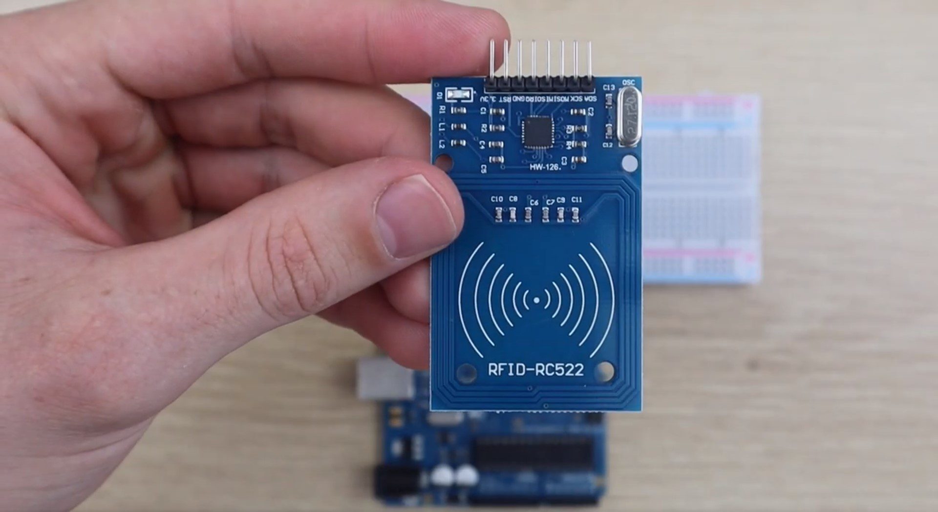
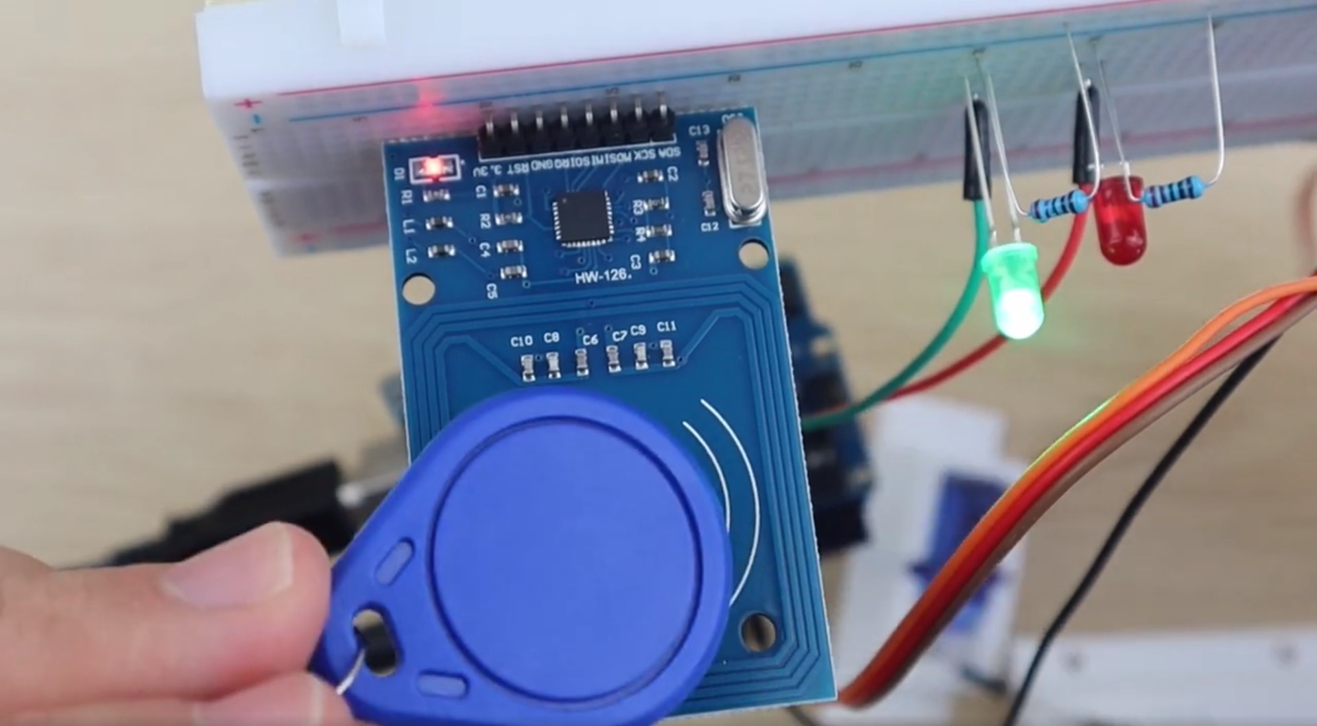
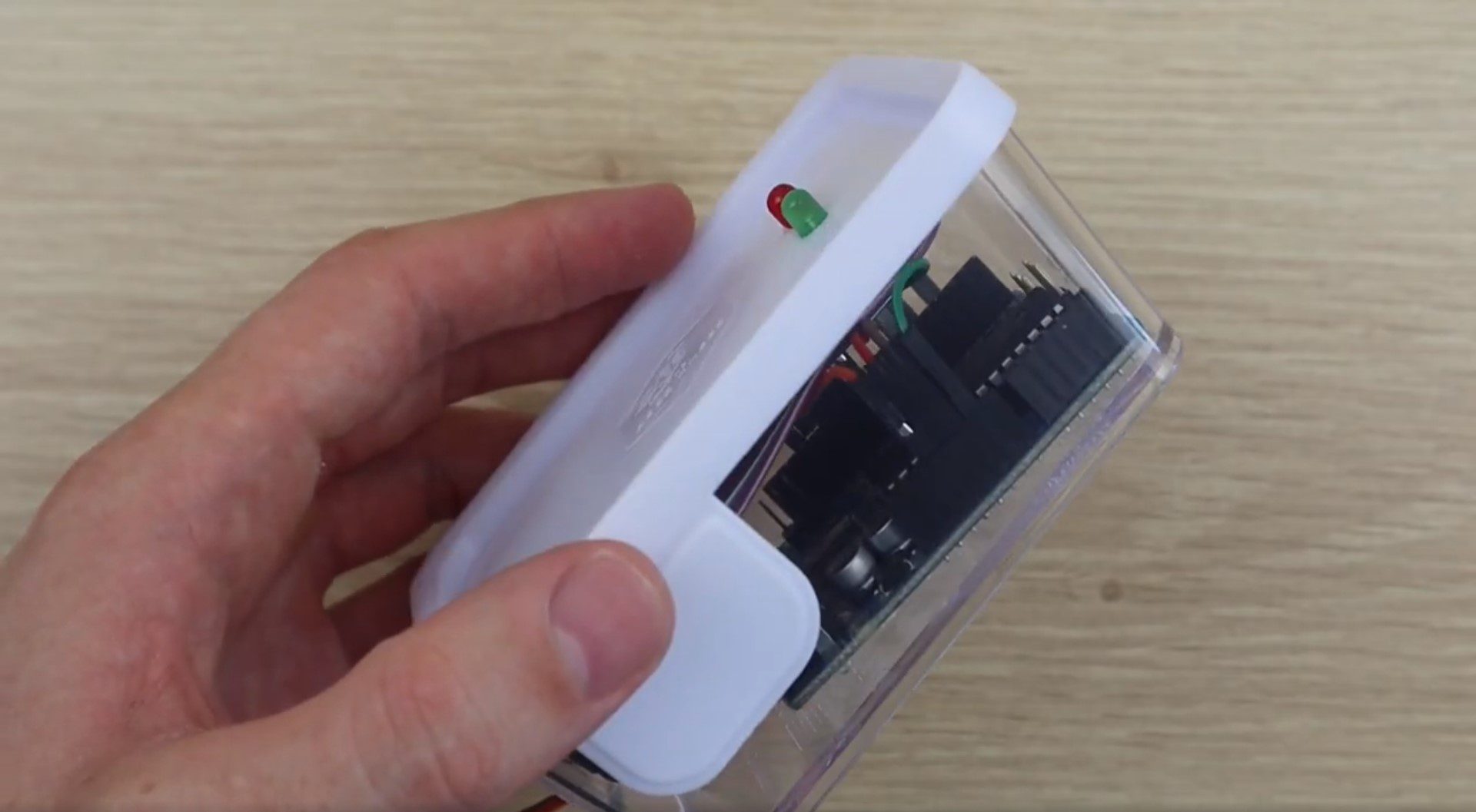
This is a really easy RFID door lock mechanism which is based on the Arduino Uno and the RC522 RFID sensor, which allows you to use RFID tags or cards to lock and unlock a door, drawer or cupboard. You can load as many RFID tags as you’d like onto the Arduino and add or remove tags to provide more or fewer people with access. The lock is actuated with a micro servo, which can be used along with the 3D printed lock provided in this example, or any standard bolt type lock available from your local hardware store.
This guide assumes that you’ve worked with an Arduino micro-controller before and know the basics of programming an Arduino. If you do not, follow the linked guide for more information on creating and uploading your first sketch.
Here is a summary of the build, continue reading for full step by step instructions along with the code and print files:
What You Need To Make Your Own Arduino Based RFID Lock
3D Printer & Filament (Optional for Lock) – This One Used
How To Make Your RFID Door Lock
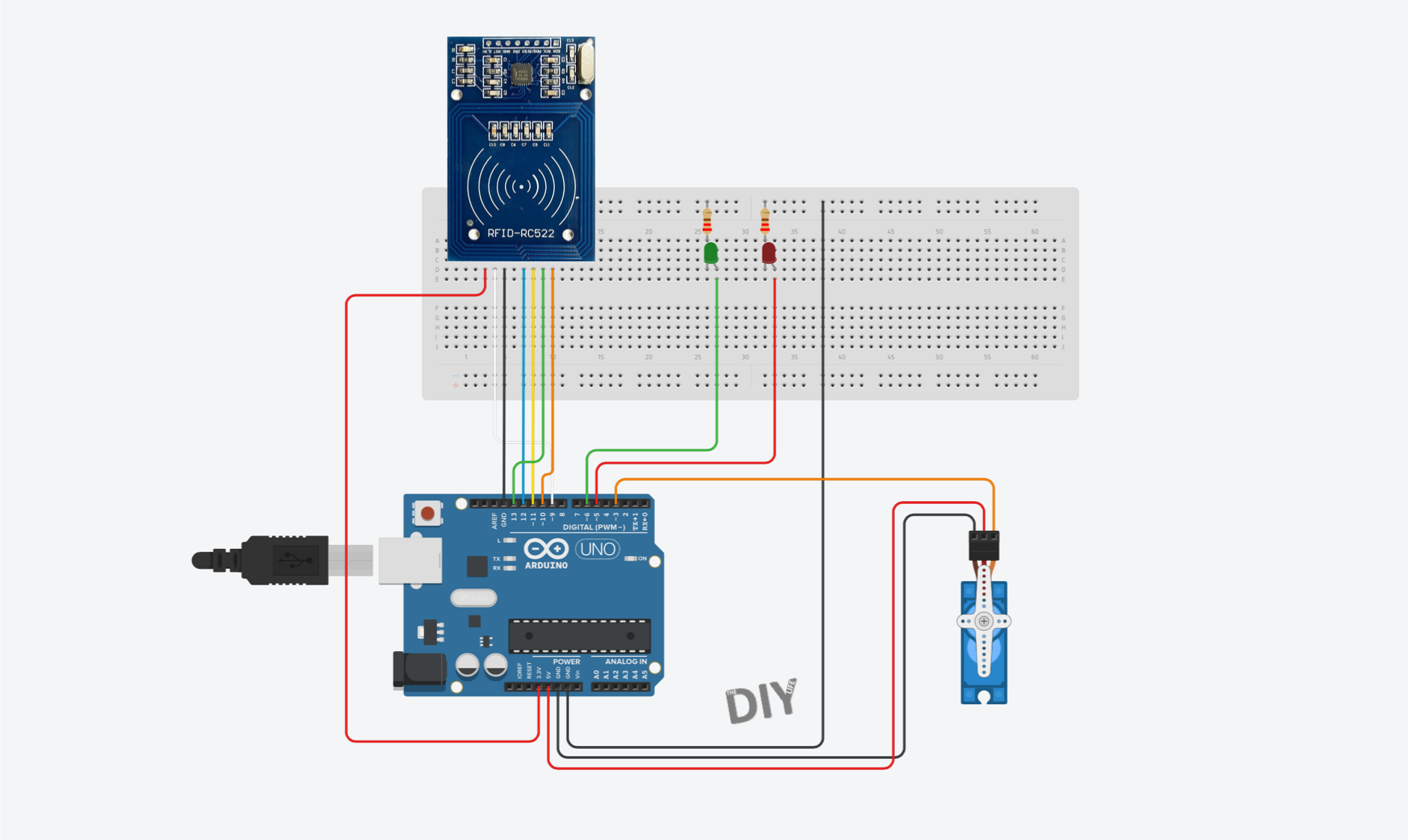
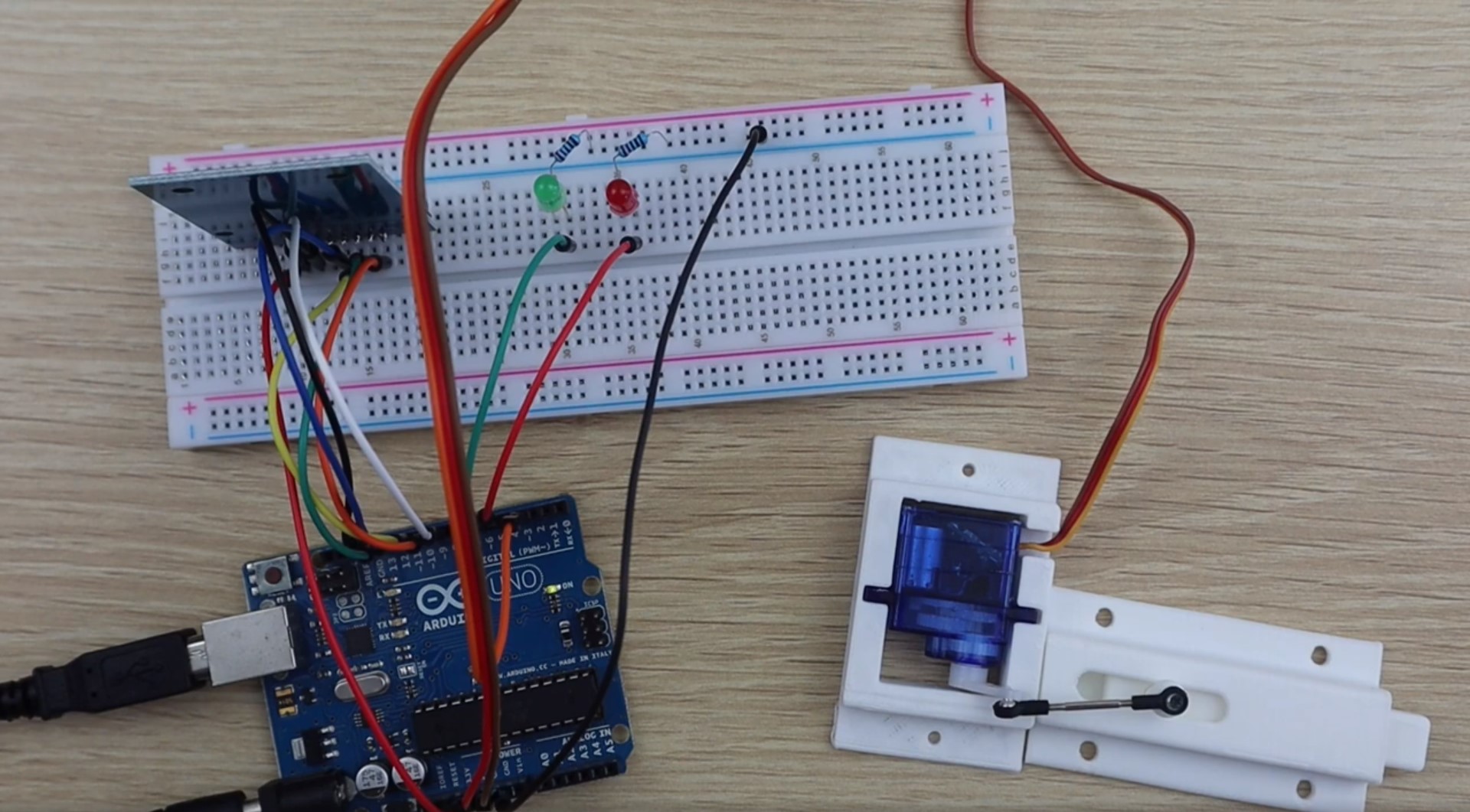
To start off, lets connect the RFID sensor, LEDs and servo to your Arduino using a breadboard. This will enable you to test the circuits and to read the serial numbers from your tags in order to load them into the array in your code so that they open the lock.
The Circuit
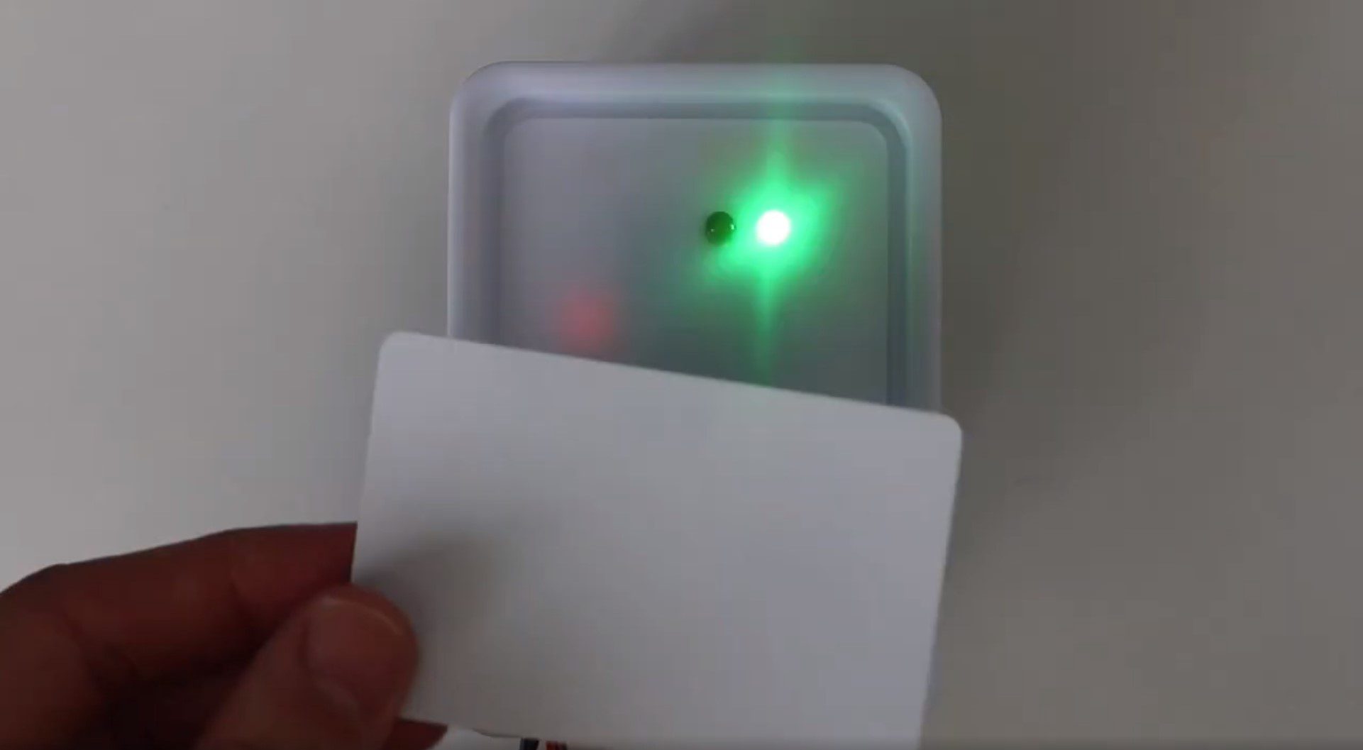
The RC522 sensor is going to be connected to our Arduino using the SPI interface. We are then going to connect a green LED which will flash to show that a tag has been read and access has been granted and a red LED which will flash to indicate that a tag has been read an access has not been granted. Lastly, a micro servo will be used to open and close the locking mechanism. The LEDs and micro servo are connected using typical Arduino circuits.
Here is the circuit:
Once you’ve got the circuit connected on your breadboard, you’ll need to print and assemble your lock mechanism.
Building The Lock Mechanism
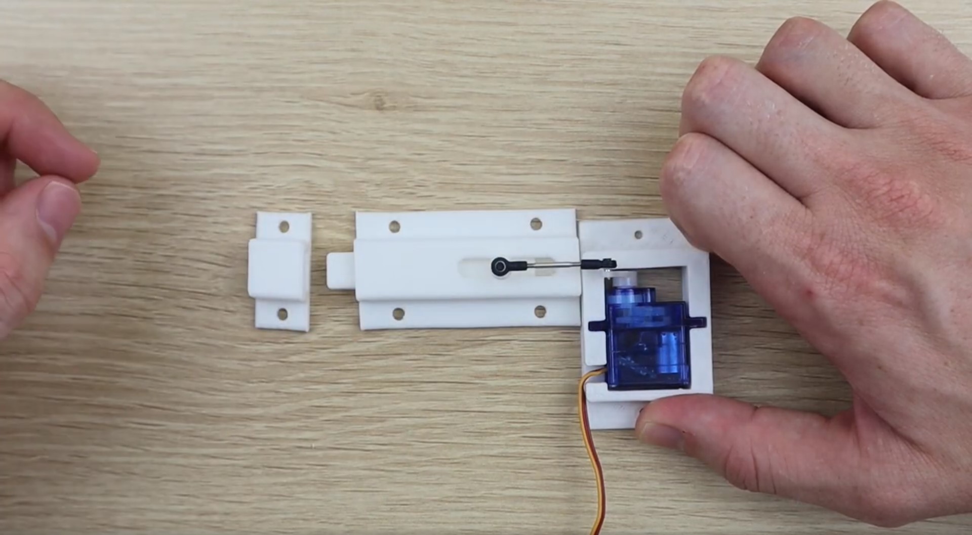
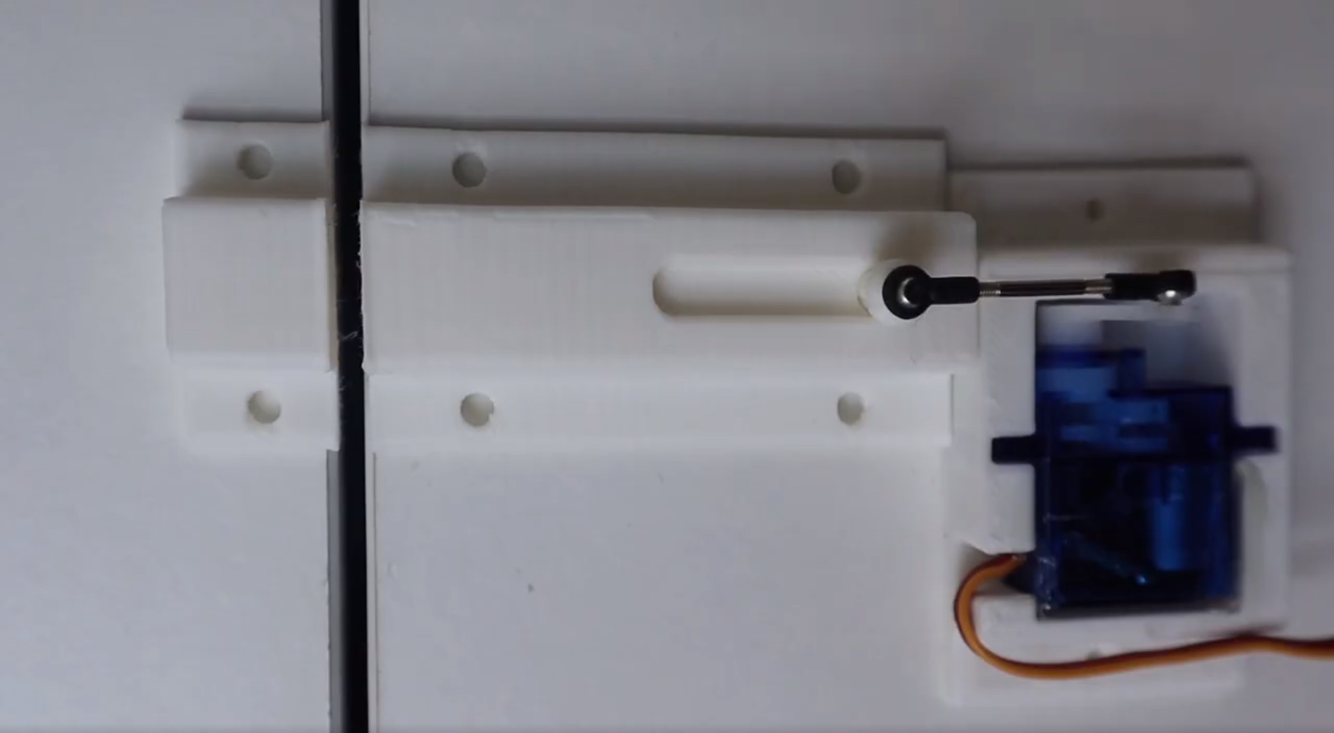
If you’ve got a 3D printer, the easiest way to get started with an RFID door lock is to print out the below components and servo bracket. The lock mechanism is based on this sliding lock design by Sagittario which I have scaled down to 65% of the original size.
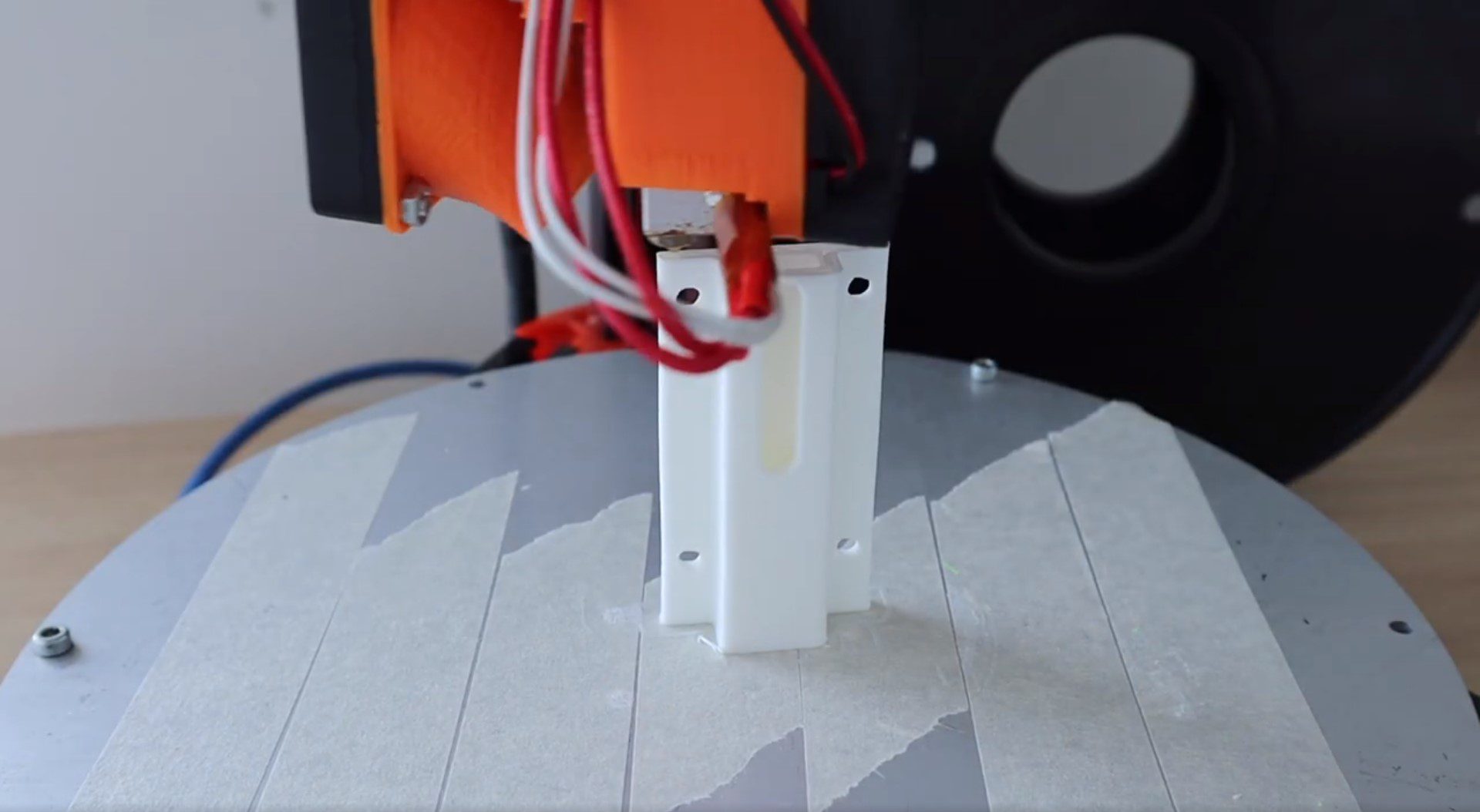
I 3D printed the lock mechanism and servo holder using white PLC at 185C and 20% infill.
If you don’t have a 3D printer, you can use any standard bolt type sliding lock available from your local hardware store. You’ll just need to attach one end of the servo push rod to the bolt to actuate it. You’ll also need to build a simple servo bracket to hold the servo in place behind the lock. You can just epoxy or glue the servo in place, but a screwed on bracket is usually a bit stronger.
Uploading The Code
Once you’ve assembled your lock mechanism, you’re ready to upload your code and load your tag numbers into the array.
Here is the code:
//The DIY Life
//Michael Klements
//27 January 2020

#include <SPI.h>
#include <RFID.h>
#include <Servo.h>

RFID rfid(10, 9);       //D10:pin of tag reader SDA. D9:pin of tag reader RST
unsigned char status;
unsigned char str[MAX_LEN]; //MAX_LEN is 16: size of the array

String accessGranted [2] = {"310988016", "19612012715"};  //RFID serial numbers to grant access to
int accessGrantedSize = 2;                                //The number of serial numbers

Servo lockServo;                //Servo for locking mechanism
int lockPos = 15;               //Locked position limit
int unlockPos = 75;             //Unlocked position limit
boolean locked = true;

int redLEDPin = 5;
int greenLEDPin = 6;

void setup()
{
  Serial.begin(9600);     //Serial monitor is only required to get tag ID numbers and for troubleshooting
  SPI.begin();            //Start SPI communication with reader
  rfid.init();            //initialization
  pinMode(redLEDPin, OUTPUT);     //LED startup sequence
  pinMode(greenLEDPin, OUTPUT);
  digitalWrite(redLEDPin, HIGH);
  delay(200);
  digitalWrite(greenLEDPin, HIGH);
  delay(200);
  digitalWrite(redLEDPin, LOW);
  delay(200);
  digitalWrite(greenLEDPin, LOW);
  lockServo.attach(3);
  lockServo.write(lockPos);         //Move servo into locked position
  Serial.println("Place card/tag near reader...");
}

void loop()
{
  if (rfid.findCard(PICC_REQIDL, str) == MI_OK)   //Wait for a tag to be placed near the reader
  {
    Serial.println("Card found");
    String temp = "";                             //Temporary variable to store the read RFID number
    if (rfid.anticoll(str) == MI_OK)              //Anti-collision detection, read tag serial number
    {
      Serial.print("The card's ID number is : ");
      for (int i = 0; i < 4; i++)                 //Record and display the tag serial number
      {
        temp = temp + (0x0F & (str[i] >> 4));
        temp = temp + (0x0F & str[i]);
      }
      Serial.println (temp);
      checkAccess (temp);     //Check if the identified tag is an allowed to open tag
    }
    rfid.selectTag(str); //Lock card to prevent a redundant read, removing the line will make the sketch read cards continually
  }
  rfid.halt();
}

void checkAccess (String temp)    //Function to check if an identified tag is registered to allow access
{
  boolean granted = false;
  for (int i=0; i <= (accessGrantedSize-1); i++)    //Runs through all tag ID numbers registered in the array
  {
    if(accessGranted[i] == temp)            //If a tag is found then open/close the lock
    {
      Serial.println ("Access Granted");
      granted = true;
      if (locked == true)         //If the lock is closed then open it
      {
          lockServo.write(unlockPos);
          locked = false;
      }
      else if (locked == false)   //If the lock is open then close it
      {
          lockServo.write(lockPos);
          locked = true;
      }
      digitalWrite(greenLEDPin, HIGH);    //Green LED sequence
      delay(200);
      digitalWrite(greenLEDPin, LOW);
      delay(200);
      digitalWrite(greenLEDPin, HIGH);
      delay(200);
      digitalWrite(greenLEDPin, LOW);
      delay(200);
    }
  }
  if (granted == false)     //If the tag is not found
  {
    Serial.println ("Access Denied");
    digitalWrite(redLEDPin, HIGH);      //Red LED sequence
    delay(200);
    digitalWrite(redLEDPin, LOW);
    delay(200);
    digitalWrite(redLEDPin, HIGH);
    delay(200);
    digitalWrite(redLEDPin, LOW);
    delay(200);
  }
}
Before you upload your code, you’ll need to install the RFID library which is bundled with the sketch zip file. This is easily done in your Arduino IDE by clicking on Sketch -> Include Library -> Add .ZIP Library and the selecting the zipped library file.
In the code we first include the required libraries and then set up the sensor object and an array to return the read tag serial number.
The next array and its associated size is used to store the serial numbers for all of the tags which you’d like to grant access to. You’ll need to find and update these numbers using the serial monitor by uploading this code and then scanning your tags. The Serial monitor will display the tag’s serial number and then state that access is denied. Copy this number into the array accessGranted, update the array size (number of tags registered) and then re-upload the code. You could also write a short section to enable you to register a new tag by pushing a button inside the sensor component box or inside the door for example.
We then set up the servo object and it’s travel limits. You may need to make adjustments to these limits to get your servo to move through it’s full range without over-travelling in either direction.
In the setup code, we connect to the RFID sensor, define the LED pins and then run through a quick LED flash startup sequence before making sure that the lock is in the locked position. You can remove the Serial monitor output lines in the code in your final version, these are just useful for registering your tags and debugging the system when you first assemble it.
We then run through the loop which waits for a card or tag to be scanned, determines its serial number and then passes this serial number through to a function called checkAccess to verify whether the tag number can grant access or not.
The checkAccess function simply takes the read tag number and then cycles through the array of accepted numbers to see if it is an accepted tag. If a match is found then the green LED is flashed and the lock is either opened or closed, depending on the previous state. If the tag number is not found in the array then the red LED is flashed and the lock is not opened.
Adding or Removing Accepted Tags
As mentioned in the previous step, the array accessGranted is used to store the serial numbers of the accepted tags and the integer accessGrantedSize stores the number of entries in this array.
To add a tag, you’ll need to scan the tag with the Serial monitor open on your PC. You’ll then get a message saying that the card has been read along with the serial number of the card and a message saying “Access Denied”. Simply copy this number into the array and update the size integer to reflect the new number of tags. Re-upload the code and you should now get an “Access Granted” message on the Serial monitor.
To remove a tag, find the tag serial number in the array (you may need to scan it as done previously) and remove it from the array. Update the array size for any tags which you remove as well.
It is fairly easy to include a push-button or two on the inside of the door or in the component box which will allow you to add or remove tags without having to update the code.
Using the Lock
You should now have a functioning RFID locking mechanism which can be easily installed onto a door, cupboard or container to restrict access to it. You can also put the sensor components into a simple container or housing to mount on the front side of the door, like this:
There are a couple of ways to make this lock a bit more secure if you’re actually going to be using it to secure a room or cupboard.
Start by replacing the 3D printed lock with a proper metal lock from a hardware store. Make sure that you have a solid connection between the lock and the servo and try to position the servo such that the arm is in line with the push-rod and the head of the slider when it is in the locked position. This will ensure that you can’t slip a thin object through the gap in the door and try to push the slider open, you’ll be pushing against the centre of the servo and not relying on the torque provided by the servo to keep the slider in place.
Next, place as few of the electronic components outside as possible. It is better to have the actual Arduino and servo connection inside the room or box and place only the RFID sensor and LEDs outside. It’s much more difficult to trick the Arduino into opening the lock using the RFID sensor connection than it is to simply provide a PWM signal to the servo to unlock the door.
Have you built your own RFID door lock using an Arduino? Is there anything you’d suggest doing differently?Let us know in the comments section below.
Being able to control your Arduino using an infrared remote control opens up a lot of possibilities for inputting data into your Arduino and getting it to respond to certain commands in order to change functionality or drive components. You could use an infrared remote control to control a robot or car, turn a light bulb on or off or change your program from one function to another.
You can use almost any infrared remote control to control your Arduino as you’re going to be decoding the signal sent from the control. Some Arduino kits are sold with a remote control or your could use your control from a TV, appliance or toy.
Pushing a button on the remote control causes the control to emit a coded infrared signal which is unique to each button on the control, allowing the appliance to determine which button was pressed and respond accordingly.
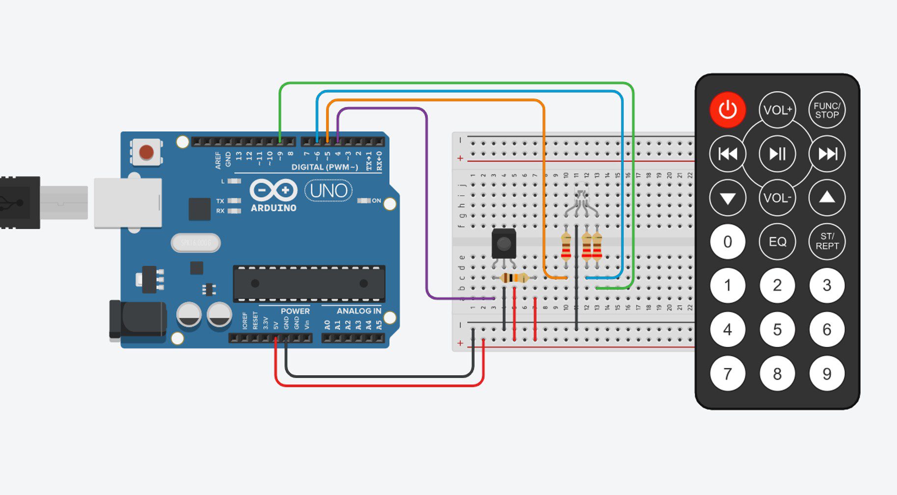
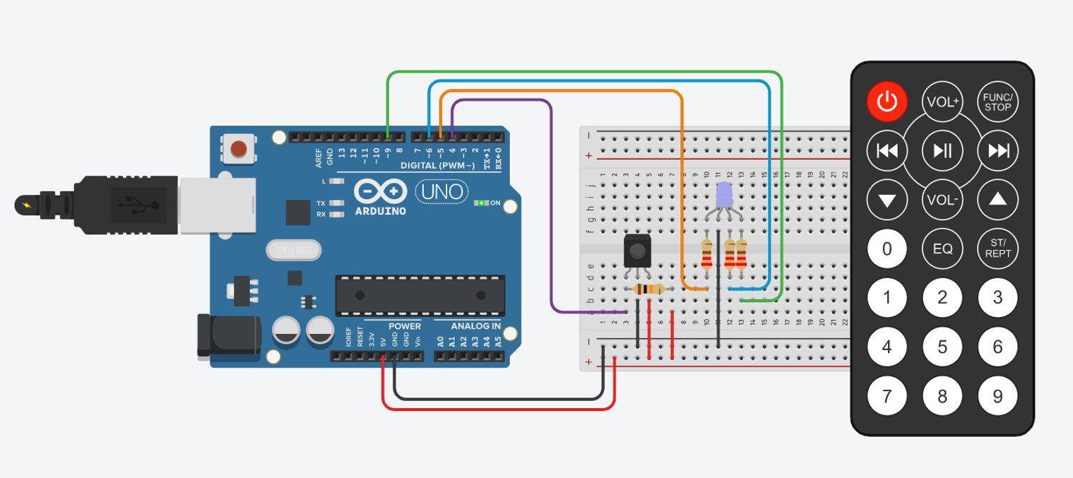
What You’ll Need To Control Your Arduino With An Infrared Remote Control
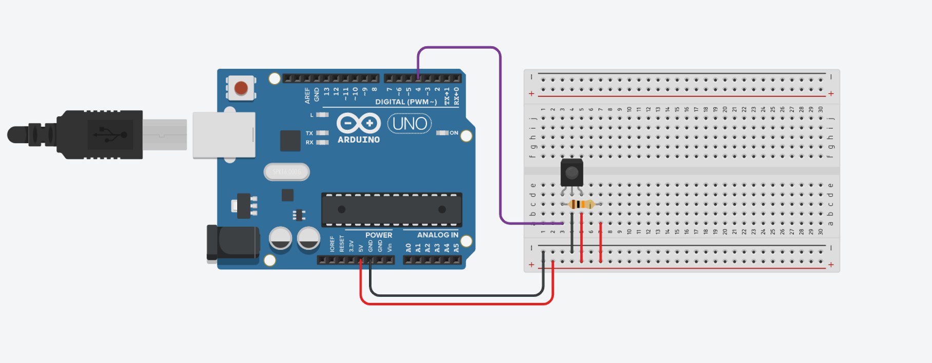
Your IR sensor will have three pins, these are 1 DATA, 2 GND and 3 VCC. To connect your sensor to your Arduino, you’ll need to power your sensor with 5V and GND on your Arduino and then connect your 1 DATA pin to an available output pin with a 10K resistor to 5V, as shown in the breadboard example below:
This is the only circuit you need to connect in order to be able to read IR signals from a remote control. In this example, we’re going to be using a remote control to control the brightness and colours of an RGB LED.
We’re going to use the numerical keypad so that numbers 1,2,3 increase the brightness of red, green and blue correspondingly, 4,5,6 decrease the brightness and 7,8,9 turn each colour off completely. The power button is additionally used to turn off all three colours completely.
We’ll need to add the LED and resistors to our breadboard as shown:
And that’s all you need to connect to be able to control your RGB LED with a remote control.
The Code
Now lets look at the code we need in order to read the value from our remote control and use it to control our RGB LED. We’ll be using the IRremote.h library to read the value from the remote control and convert the signal into a HEX value which we can then use to control our LED.
Here is the sketch:
//The DIY Life
//Michael Klements
//24 January 2020

#include <IRremote.h>

int iRPin = 4;            //IR sensor connected to Pin 4
IRrecv irrecv(iRPin);     //Create an IR object of the class
decode_results results;

int ledRPin = 5;      //Define LED pin numbers
int ledGPin = 9;
int ledBPin = 6;

int rVal = 512;       //Define initial brightness values - mid brightness
int gVal = 512;
int bVal = 512;

void setup()
{
  //Serial.begin(9600);     //Only used to get HEX value for each button
  irrecv.enableIRIn();        //Start the IR receiver
  pinMode(ledRPin, OUTPUT);   //Define the LED pins
  pinMode(ledGPin, OUTPUT);
  pinMode(ledBPin, OUTPUT);
}

void loop()
{
  if (irrecv.decode(&results))  //Wait for an IR signal to be received
  {
    //Serial.println(results.value, HEX);   //Only used to get HEX value for each button
    changeLED(results.value);    //Change the LED accordingly
    irrecv.resume();             //Wait for next signal
    delay(100);
  }
}

void changeLED(unsigned long value)
{
  switch (value)  //Determine which button has been pressed
  {
    case 0xFD08F7:    //Button 1 Pressed - Brighten Red
      if(rVal<=973)   //Stops red value from going too high, out of range
        rVal = rVal + 50;  //Increase red brightness
      analogWrite(ledRPin,rVal);
      break;
    case 0xFD28D7:      //Button 4 Pressed - Dim Red
      if(rVal>=50)    //Stops red value from going too low, out of range
        rVal = rVal - 50;  //Decrease red brightness
      analogWrite(ledRPin,rVal);
      break;
    case 0xFD18E7:      //Button 7 Pressed - Turn Red Off
      analogWrite(ledRPin,0);
      break;
    case 0xFD8877:    //Button 2 Pressed - Brighten Green
      if(gVal<=973)
        gVal = gVal + 50;
      analogWrite(ledGPin,gVal);
      break;
    case 0xFDA857:      //Button 5 Pressed - Dim Green
      if(gVal>=50)
        gVal = gVal - 50;
      analogWrite(ledGPin,gVal);
      break;
    case 0xFD9867:      //Button 8 Pressed - Turn Green Off
      analogWrite(ledGPin,0);
      break;
    case 0xFD48B7:    //Button 3 Pressed - Brighten Blue
      if(bVal<=973)
        bVal = bVal + 50;
      analogWrite(ledBPin,bVal);
      break;
    case 0xFD6897:      //Button 6 Pressed - Dim Blue
      if(bVal>=50)
        bVal = bVal - 50;
      analogWrite(ledBPin,bVal);
      break;
    case 0xFD58A7:      //Button 9 Pressed - Turn Blue Off
      analogWrite(ledBPin,0);
      break;
    case 0xFD00FF:      //Power Button Pressed - Turn All LEDs Off
      analogWrite(ledRPin,0);
      analogWrite(ledGPin,0);
      analogWrite(ledBPin,0);
      break;
  }
}
I’ve put comments into the code to guide you through it and explain what each section does.
The two Serial lines which are commented out are needed when you first set up the code. You’ll need to uncomment the lines, run the sketch with your Serial monitor open and then push the 10 buttons used in this example on your own remote control in order to check and record the HEX values, it is unlikely that they will be the same as used in this example unless you happen to have the same remote. Record the values which are displayed for each button and then replace the values in the code. For example, replace 0xFD00FF for the power button with the new code shown on your Serial monitor. You’ll leave the 0x preceding the 6 digit code which you’ll have displayed.
Once you’ve made these changes then the code should run and your Arduino should respond to your remote control button pushes.
The code in the changeLED function is used to respond to each button press by using a switch statement to switch between the different buttons. You can add or remote buttons to this statement by adding or removing additional case lines.
If you use a different remote control or two remote controls, simply replace the values next to each case to correspond with your new remote’s values displayed in the Serial monitor. For two remote controls, duplicate cases line with your additional value as a second option.
You should now know enough to get your Arduino to respond to commands sent to it by one or more IR remote controls. Have you tried connecting an IR remote to your Arduino? What did you build and how did it go for you? Let us know in the comments section below.
As mobile phone costs continue to increase, most new iPhone buyers are hoping to get a few years worth of use out of each device. It is not uncommon for people to hold onto an iPhone for 4 or 5 years. In this article we take a look at some ways you can take better care of your iPhone to help you get the longest life out of it, keeping it going for many years to come.
Most of these tips pertain to the battery and how you charge your iPhone. This is because the battery is usually the first component to start packing up and one of the biggest reasons people land up getting a new iPhone. If your iPhone battery is already on its way out, there is good news, you can replace your iPhone battery yourself.
Keep Your iPhone Cool – Especially When Charging
Heat is one of the quickest killers of batteries and modern electronics, and the same holds true for your iPhone. Don’t leave your iPhone in a hot car, in the sun or in a place where it’s going to be kept hot for extended periods of time.
This also holds true when you’re charging your iPhone. Don’t charge it in confined or closed up spaces and if you’re using a bulky cover, get into a habit of removing it when charging your phone. The cover traps in the heat and reduces your iPhone’s ability to keep itself cool, reducing the life of the components and the battery.
You should also avoid wireless charging your iPhone too often. Wireless chargers are definitely a convenient way to charge your phone, and are becoming more prevalent in restaurants and airports, but you should avoid using them as your everyday charger as they also generate excess heat which in turn reduces the life of your battery.
Clean Your iPhone With A Microfiber Cloth
Keep your iPhone clean by periodically wiping it down with damp microfiber cloth. Unless your iPhone is really dirty, you shouldn’t need any chemicals. Harsh chemicals may damage the oleo-phobic coating on the display or the paint on the back and sides. If your device is heavily soiled or you’d like to give your iPhone a thorough clean, the best thing to use is eyeglass wipes which are stated as safe for use on anti-reflective coatings. These won’t damage the coating on your display or the finish on the back of your phone.
Avoid Charging Your iPhone Over 80%
Newer iPhones, running iOS 13 or later have a built in software function called optimised battery charging. This is a software feature which learns from your day to day charging habits and prevents your iPhone from charging to full capacity for extended periods or where it can get away with reduced charging. For example, if you leave your iPhone on charge overnight, it will only charge to 80% for most of the night even though its been left plugged in. Charging your battery to 100% puts it under stress, and the more stress placed on the battery, the shorter it’s lifespan will be.
If you don’t have this software feature, and just as a general rule, you should avoid charging your iPhone beyond 80% if you’re not going to need the full charge.
When your iPhone goes into an area where there is little or no phone service, it starts continuously “hunting” for reception. This causes your phone’s circuitry to work hardly and produces more heat, reducing the life of components and the battery. When you’re in an area which is known to have little or no reception, get into a habit of putting your iPhone into Airplane mode. This disables the transmitter and receiver and stops your iPhone from continuously searching for signal.
This can apply to being on an airplane, being in remote areas, underground or even on a cruise ship. If you have one bar or no signal at all then you should consider switching your phone to airplane mode until you’re back in a location with better reception.
Use The Buttons As Little As Possible
There’s a reason why Apple got rid of the home button, it was a common point of failure on their phones and anyone who has kept an iPhone for 4-5 years will likely have experienced one of the physical buttons, or the mute switch stop working.
Almost all of the functionality of the buttons and switch on your iPhone can be replicated through the software as well.
Use the auto-lock instead of the sleep/wake button, Assistive Touch instead of the TouchID/home button, turn off your iPhone from settings, adjust the volume using the slider in the Control Center, mute your phone using Do Not Disturb (although this will turn off vibrate as well).
There is no clear answer from Apple on how their phones manage storage space and whether it is used as swap space to supplement RAM, but the general consensus is that iPhone’s tend to slow down when they have less than 1GB of free storage space. So you should try and remove any unused apps and content to keep a bit of space free. Upgrading to iOS 12 on older devices frees up quite a bit of space due to the switch to HEVC and HEIF encoding and you can use iCloud to free up some storage space used for photos and documents etc..
What are some of the ways in which you’ve managed to get the longest life out of your iPhone? Let us know how old yours is and what your tips and tricks are in the comments section below.