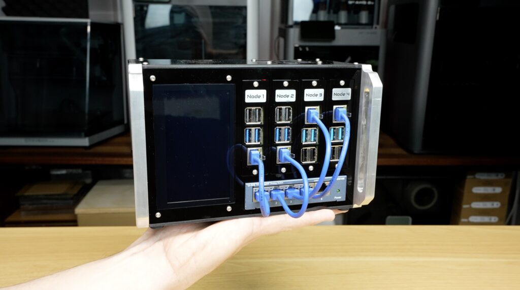
This entire Raspberry Pi cluster fits in the palm of my hand. Inside this small acrylic enclosure is four independent Raspberry Pis, their own dedicated network switch, a system monitoring display and enough compute power to run a homelab stack.
I built the entire thing myself from sheets of acrylic and aluminium using the new Makera Z1 desktop CNC machine.
Today I’m going to show you how I designed it, cut and engrave all of the parts and see if we can turn four Raspberry Pis into the cool mini datacenter.
Here’s my video of the build, read on for the write up:
Where To Buy The Components To Build Your Own Compact Pi Cluster
- Raspberry Pi 5 – Buy Here
- Raspberry Pi 4 – Buy Here
- Pi 5 Active Cooler – Buy Here
- 32GB Sandisk MicroSD Card – Buy Here
- 5 Port TP Link Network Switch – Buy Here
- 4.3″ IPS Touch Display – Buy Here
- 5V 18A Power Supply – Buy Here
- 60mm 5V Fan – Buy Here
- M3x8mm Button Head Screws – Buy Here
- M3x16mm Button Head Screws – Buy Here
- M2.5x6mm Button Head Screws – Buy Here
Tools & Equipment Used:
- Makera Z 1 Desktop CNC Machine – Buy Here
- Makera Cyclone Dust Collector Lite – Buy Here
- Makera Vacuum Bed – Buy Here
- Makera 3D Probe – Buy Here
- Weld-On #3 Acrylic Cement – Buy Here
- 3mm Black Acrylic – Buy Here
- 3mm Tinted Acrylic – Buy Here
- USB C Pencil Screwdriver – Buy Here
Some of the above parts are affiliate links. By purchasing products through the above links, you’ll be supporting my projects at no additional cost to you.
Designing The Compact Raspberry Pi Cluster Enclosure
Over the past few years, I’ve built a lot of Raspberry Pi projects, NAS systems, Routers, Homelabs & Mini racks, but apart from the large 8-node cluster that I built a while back, I’ve never revisited a Pi cluster. Not because they’re difficult to build, but because most of them just end up looking like a pile of boards cabled together.
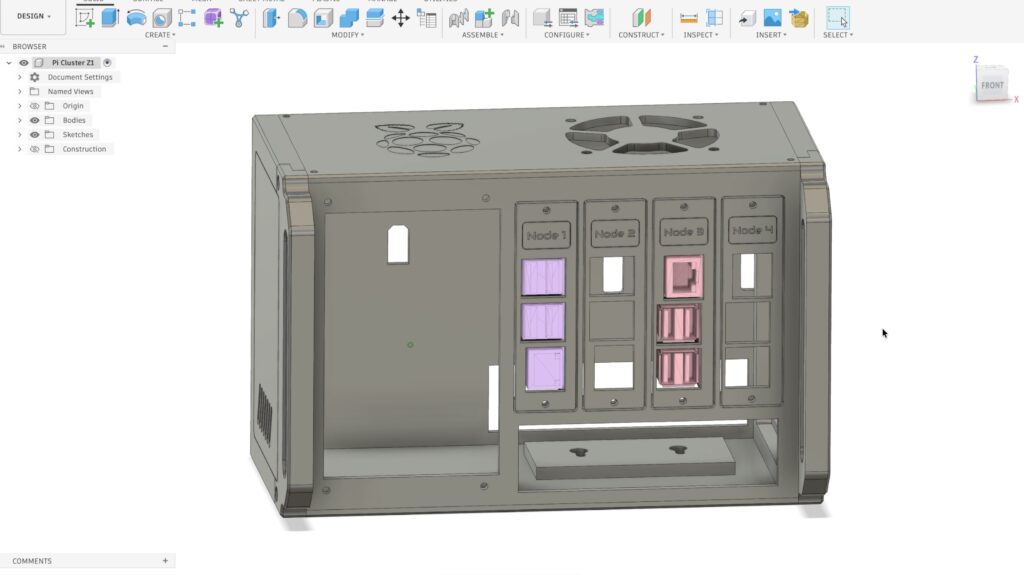
I wanted to build something that looked like a bit of thought and design had gone into it. Something that would look at home sitting on a desk. So I started by designing this.
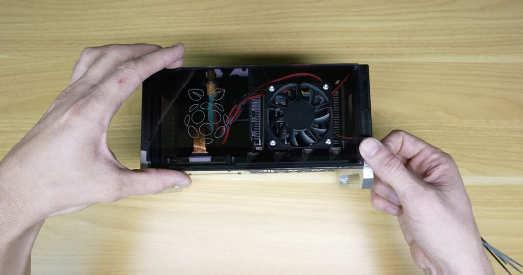
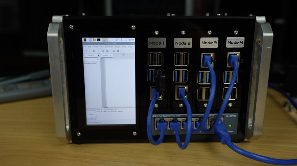
The cluster houses four Raspberry Pi’s. Two Raspberry Pi 5s and two Raspberry Pi 4s. Although the trays are swappable so you can run any combination of Pi 3, 4 and 5s. Below them is a dedicated five-port network switch, and on the left is a built-in system monitoring display.
This is all enclosed in a custom acrylic chassis with a tinted top and side panels so you can see the hardware inside it.
Node 1 is the primary Pi 5 and drives the portrait-mounted 4.3-inch DSI display alongside it. Next to it is a second Pi 5, which becomes Node 2 and so on.
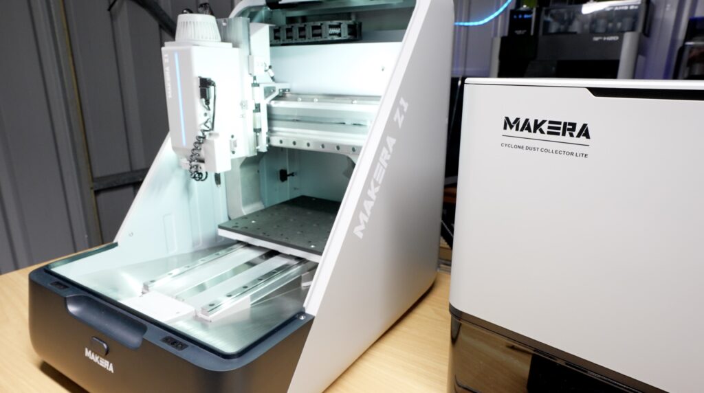
Makera Z1 Desktop CNC & Cyclone Dust Extractor Lite
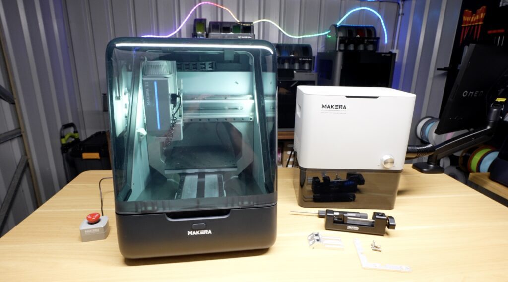
To make up the enclosure, I’m going to be using the newly launched Makera Z1 CNC machine. Makera sent over both the Z1 and their new Cyclone Dust Collector Llite system for me to try out. Unlike the last time I tested one of these, this is now a production model which they’ve made some improvements to.
One of the things I really like about it is that it’s capable of working with a wide range of materials. For this build we’re going to be cutting and engraving acrylic, cutting aluminium, engraving labels from bicolour stock and even adding chamfers to some of the edges. Normally that would require several different workshop tools.
Making Up The Acrylic Enclosure Components
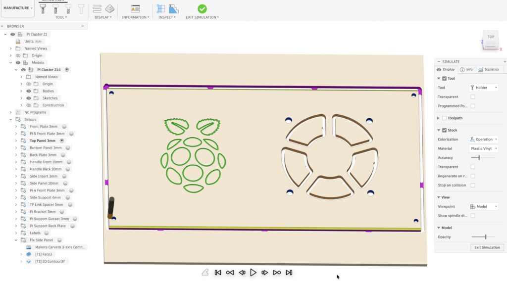
The enclosure is primarily made from acrylic, and I used Fusion360’s manufacturing workspace to create and set up the CNC files for the parts.
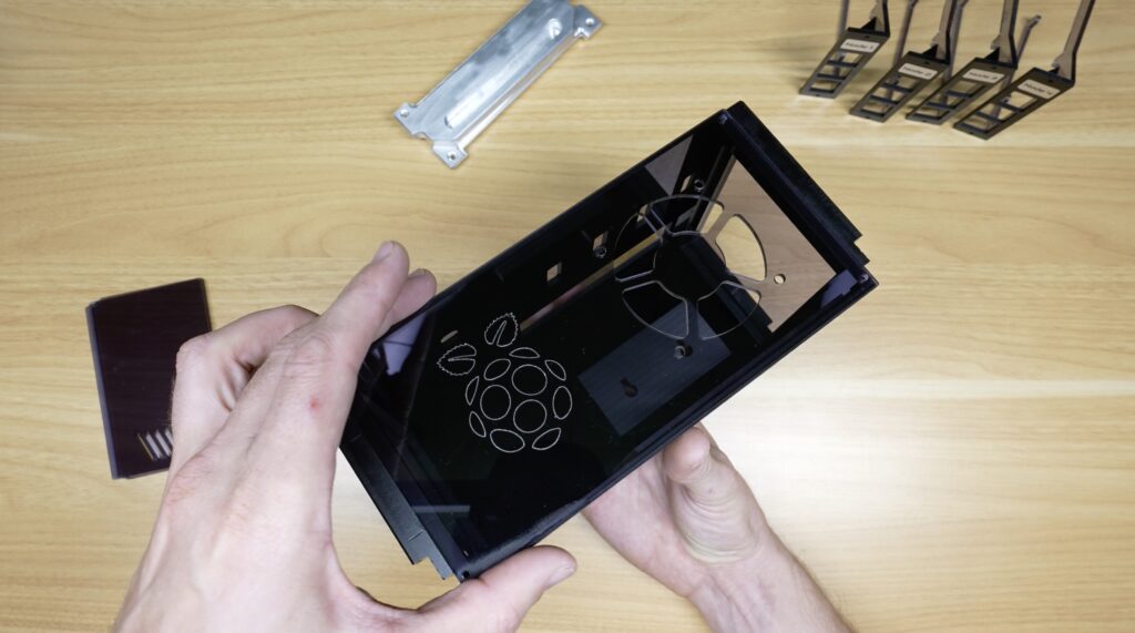
The front, rear and bottom panels are opaque black acrylic, while the top and side insert panels use a tinted grey acrylic so that the hardware remains partially visible inside.
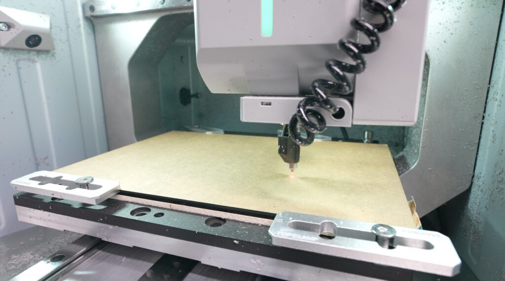
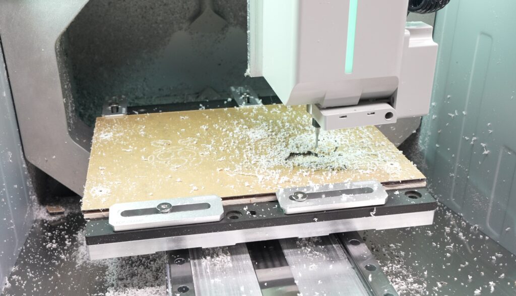
I started out by machining all of the main panel profiles. To make up these panels, I’m using Makera’s 2 millimetre diameter end mill, which leaves really clean finished edges in acrylic.
First, I made up the front panel. The Z1 has some helpful features like an outline trace to help confirm that the stock is correctly in position, and that there’s enough of it, and it also has auto levelling, which probes the bed and compensates for any gradient or warping.
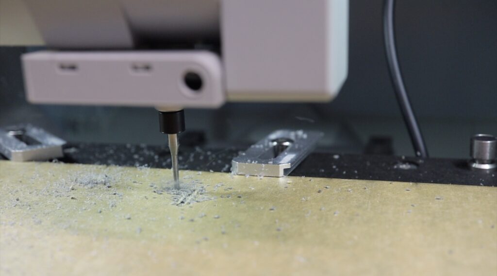
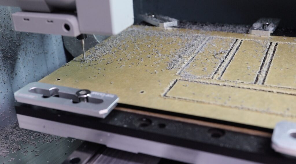
One thing I always enjoy about machining acrylic is watching the parts gradually emerge from what starts as a completely blank sheet.
One of the strengths of a CNC machine over a laser cutter is that you can precisely control the depth of cuts in materials, so you can create pockets for inlays and steps for stronger joints. I’ve used these for each node’s faceplate as well as the handles and side panels.
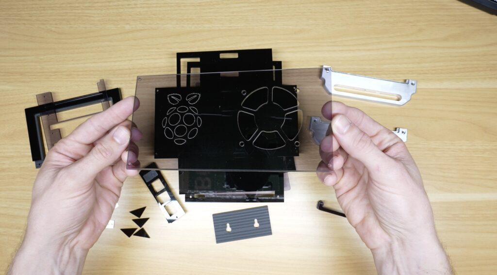
With the main profiles cut, let’s move on to the top tinted panel, which features a large Raspberry Pi logo that sits directly above the display. To do that’ we’ll switch over to an engraving bit using the Z1’s quick tool changer. The Z1 also shows you which tool to change to using the led bar on the tool head.
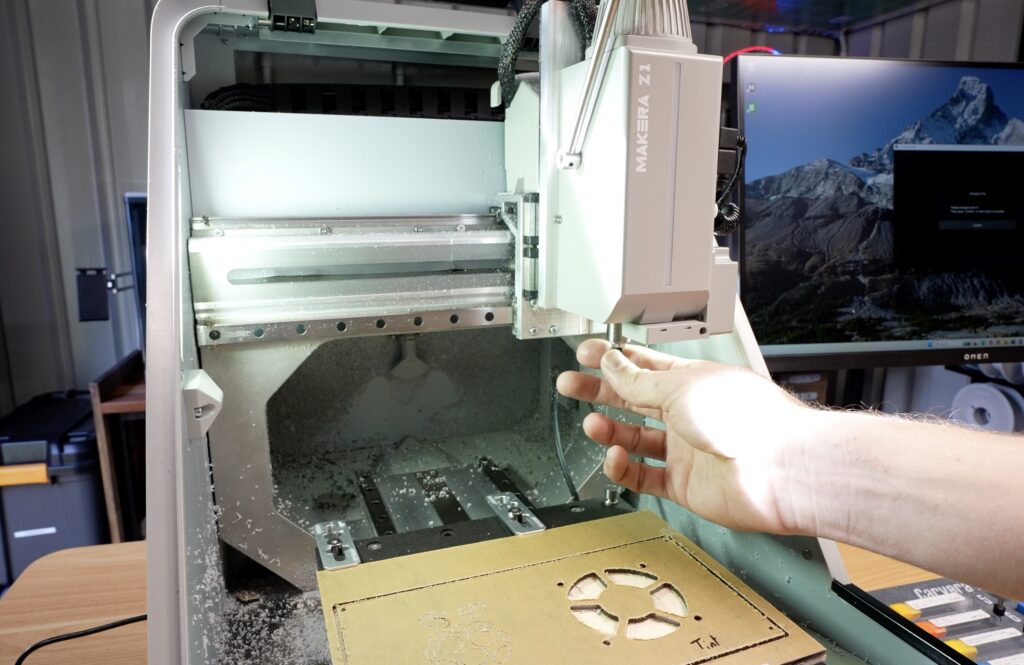
The engraving adds a nice visual detail without making the design look busy, and because it’s machined directly into the acrylic it feels a lot more premium than just adding a sticker to it.
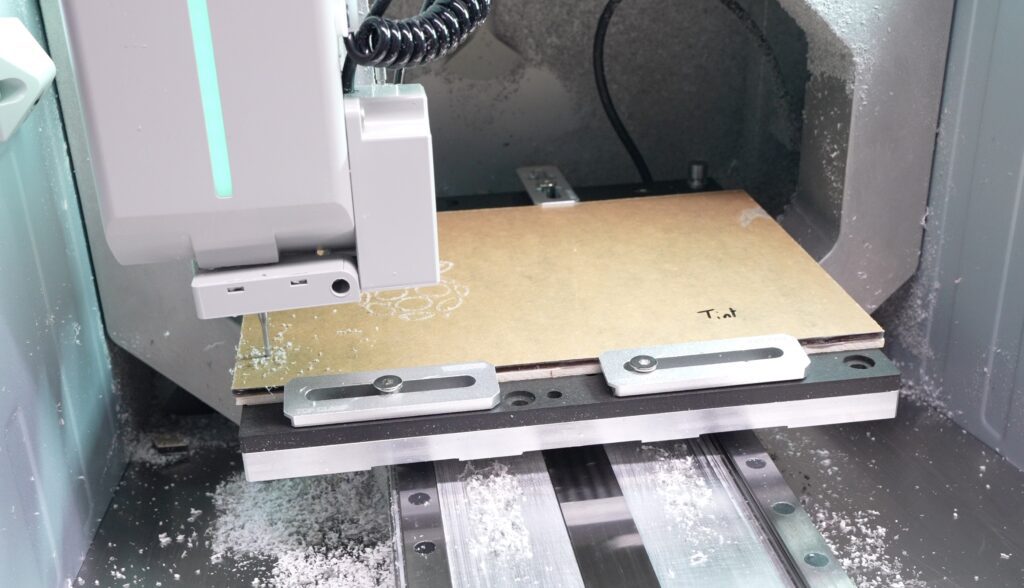
This panel also gets chamfered edges, so again we can switch tools, now over to a chamfer bit.
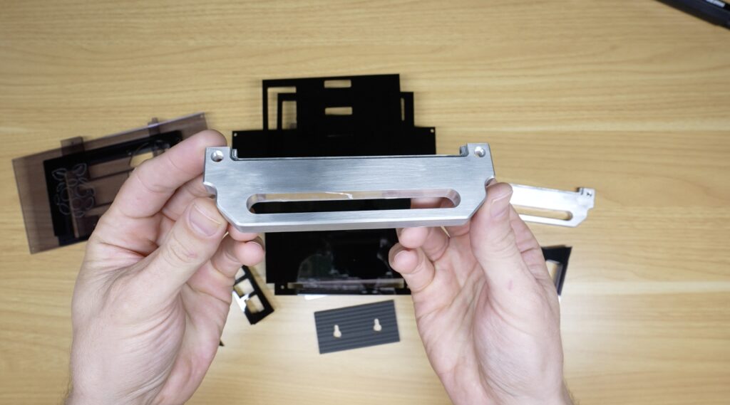
Machining The Aluminium Handles
Next, let’s make up the aluminium handles. The handles added to either side of the enclosure are decorative rather than functional, but they help reinforce a miniature rack-mount aesthetic.
To machine these, I switched over to a 1/8” metal cutting end mill. The thicker tool helps with rigidity to cut the aluminium.
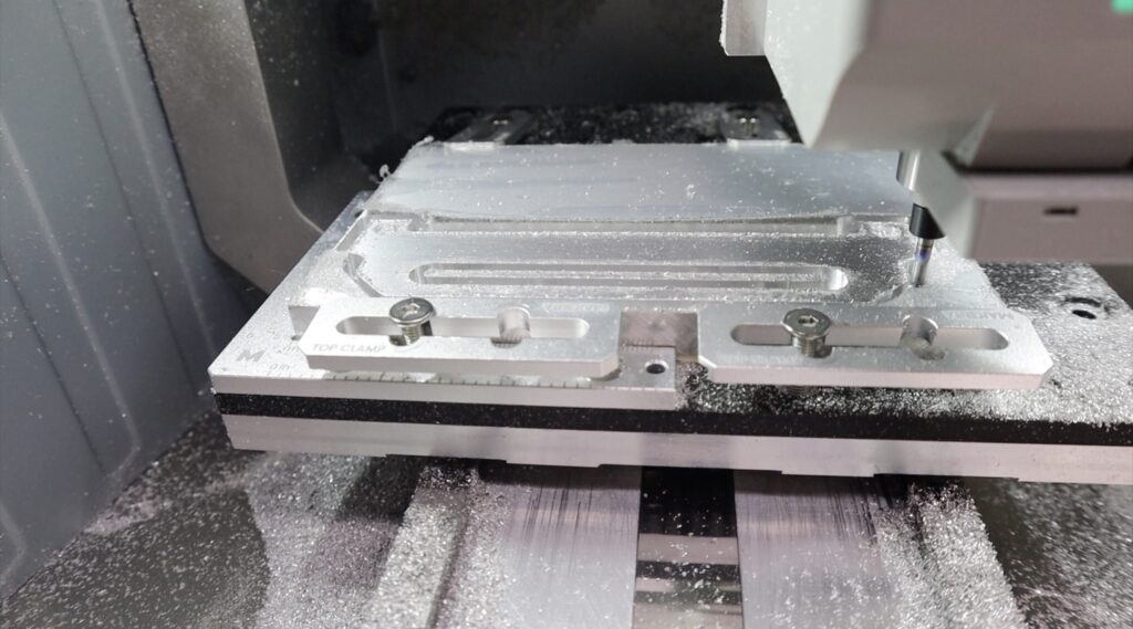
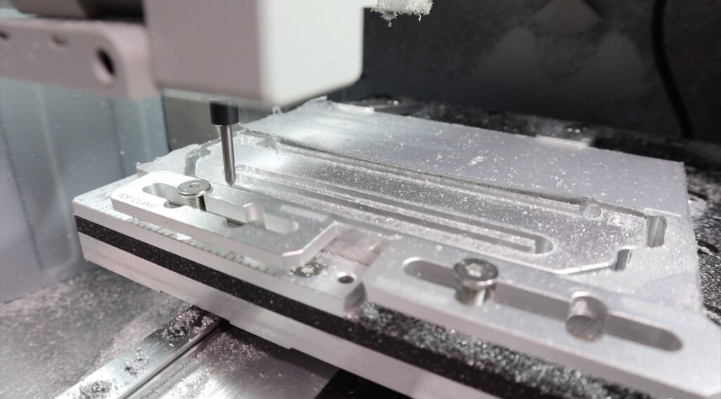
Once the outside profiles were complete, I also added chamfers to soften the edges and make them feel more like a finished product.
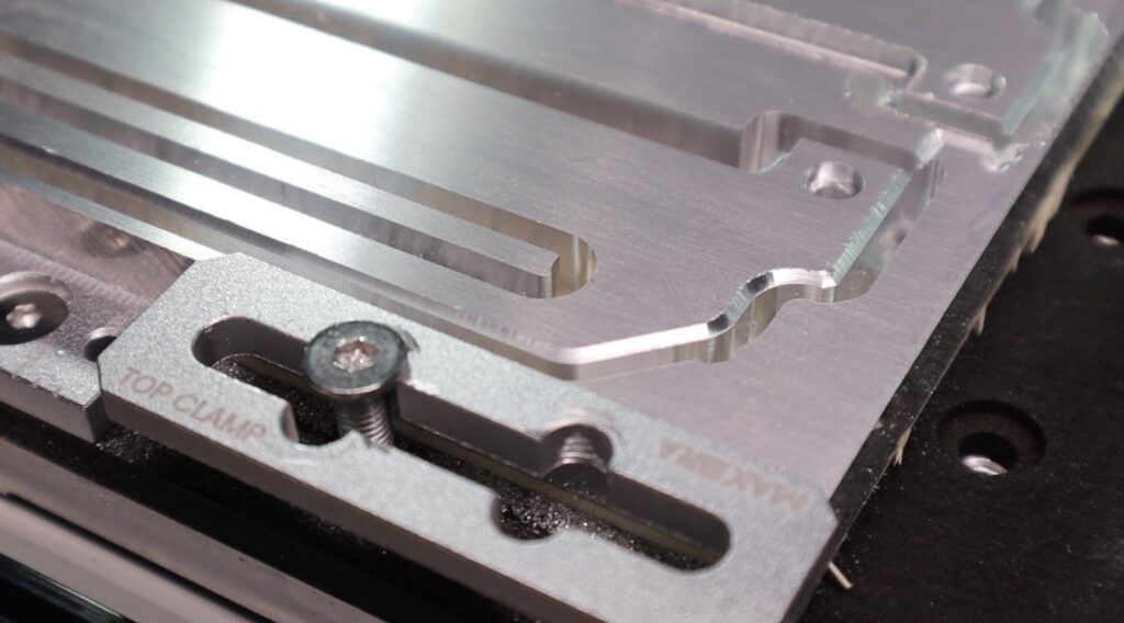
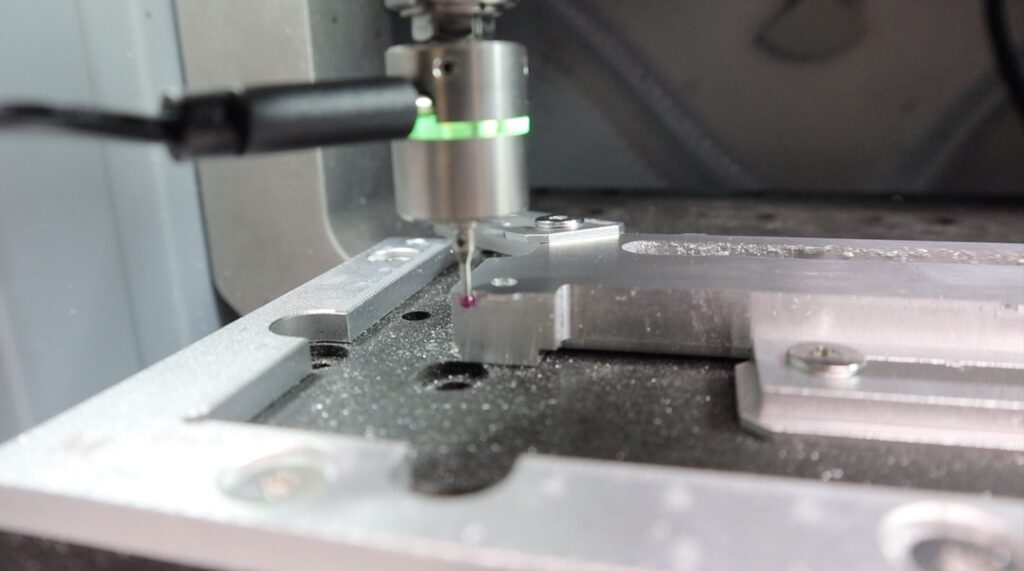
You can also get a 3D probe for the Z1, this makes it really easy to pick up a reference point for two-sided jobs or to get the centre of cylindrical work pieces. It’s load-based, so it works on both conductive and non-conductive materials. I used this to flip the handles over to machine the step on the back of the handles that interfaces with the acrylic side panels.
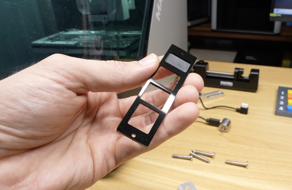
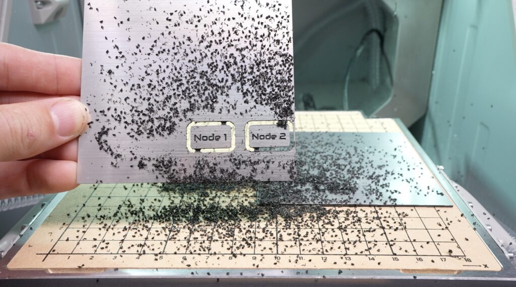
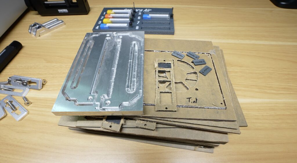
Cutting & Engraving the Node Labels
Lastly, we need to make up the aluminium labels for each node. These are cut from a piece of bi-colour stock with aluminium on the front and a black backing. To engrave and cut these, I’m going to use a cool accessory available for the Z1, a vacuum bed. This bed cleverly makes use of the cyclone dust extractor to suck the workpiece down onto the bed, allowing you to quickly and easily use thin stock without having to clamp it down each time.
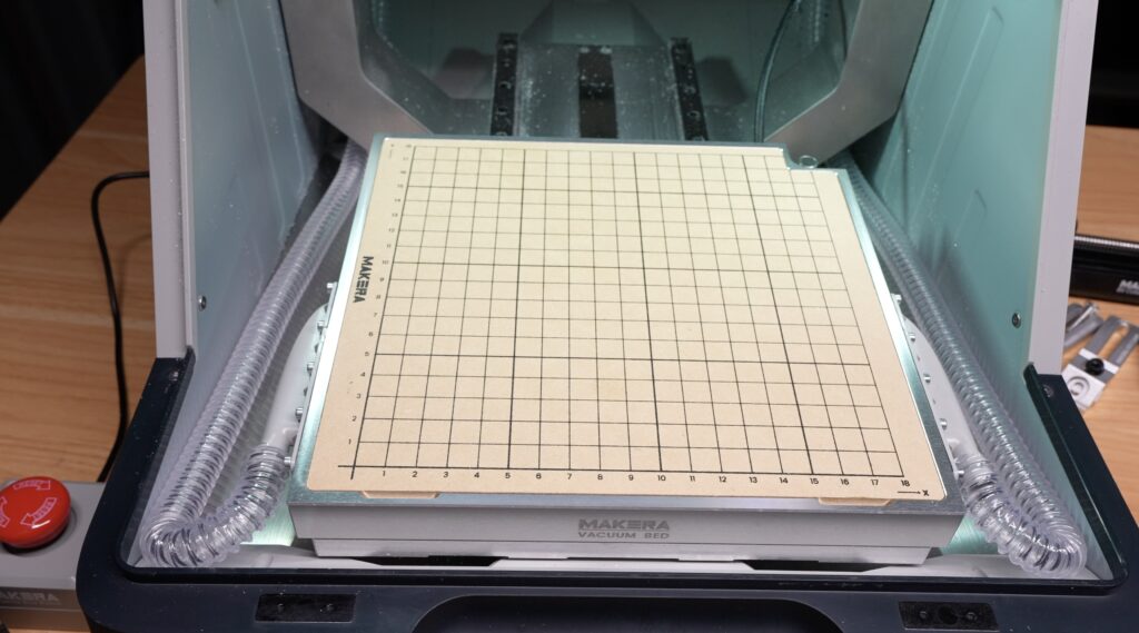
For smaller aluminium sheets like these node labels it works really well. It also means that there are no clamps getting in the way of the tool path so you can run closer to the edges.
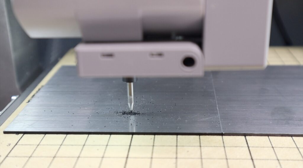
We’ll use an engraving bit to cut the label text and then an end mill to cut them out.
Finishing Off The Parts
And that’s all of the parts complete. Now, I just need to go through the usual cleanup to remove their tabs and sand the edges smooth. I did this using a combination of a Dremel rotary tool and a simple sanding block with different grit sides.
I’ve found that very fine-grit sanding blocks are great for polishing up the edges of the acrylic parts, and abrasive wheels are great in the Dremel to clean up the aluminium parts.
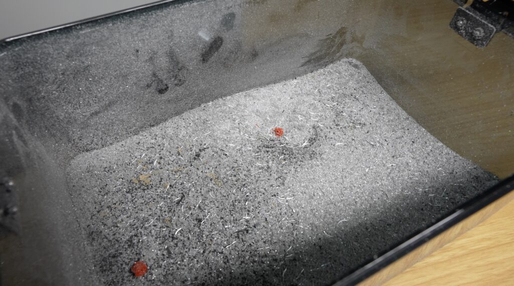
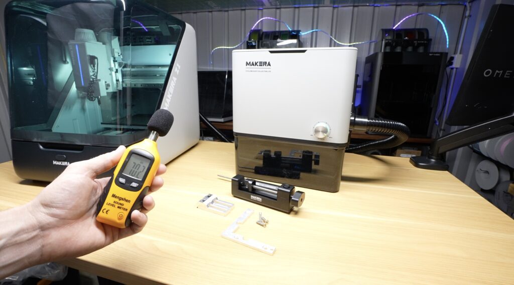
The cyclone dust collector lite works really well to collect chips during cutting and engraving and to vacuum up the inside of the Z1 after use. It’s also impressively quiet, running at just 70dB flat out, which is a lot less than a typical shop vac, which would sound about twice as loud, around 80-90dB.
Assembling The Acrylic Pi Cluster Enclosure
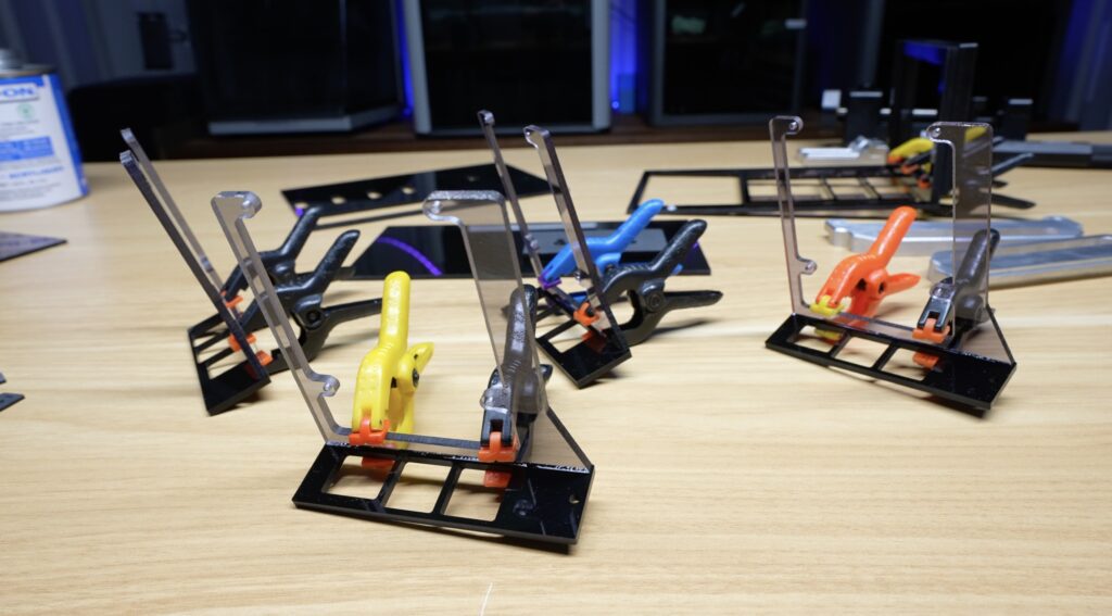
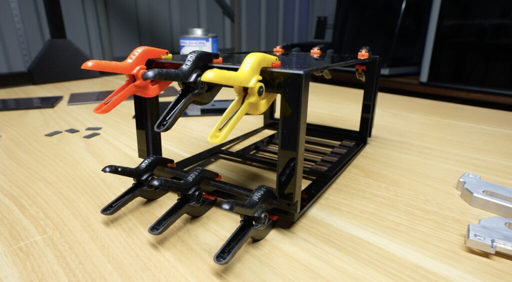
With that all done, we can then move on to assembling the acrylic compact Pi cluster enclosure.
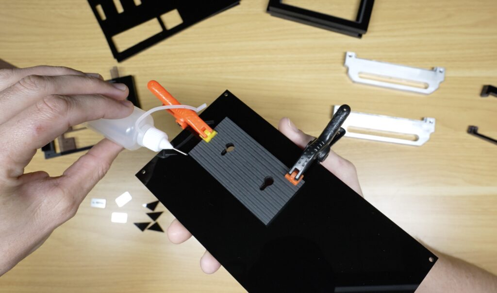
Most of the acrylic structure is bonded together using Weld-On #3 acrylic cement. This creates a really strong joint and leaves the assembly looking almost seamless. I like using this particular cement because it’s very thin, so you can set a joint using clamps and the cement wicks into the seam afterwards and creates a quick and strong bond.
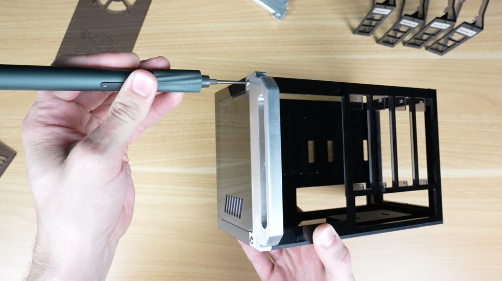
The top panel is removable and secured using four M2.5x6mm screws afterwards so that the cluster can still be serviced later.
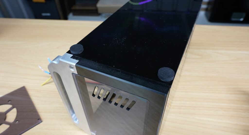
The handles are also screwed on, this time using M3x8mm screws since acrylic and aluminium don’t really like being glued together. You could use some epoxy adhesive for this but I think the two screws add some nice detail to the sides.
Lastly, I stuck some rubber feet onto the bottom so that it doesn’t slide around and has a bit of vibration dampening.
Installing The Pi’s and Electronic Components
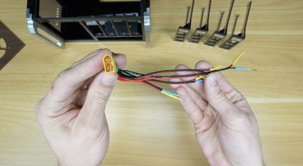
The cluster is powered from a single 5 volt power supply connected through an XT60 connector on the rear. I usually use barrel plugs for power supplies but they can’t handle the combined amperage of all four Pi nodes. Instead of having four separate USB power supplies, all four Pis are powered directly through their GPIO pins. This keeps the wiring cleaner and makes the entire system much more compact.
Each Raspberry Pi is mounted onto its own removable sled using M2.5 screws into tapped holes in the acrylic. The sleds can slide out individually if a board ever needs to be replaced or upgraded.
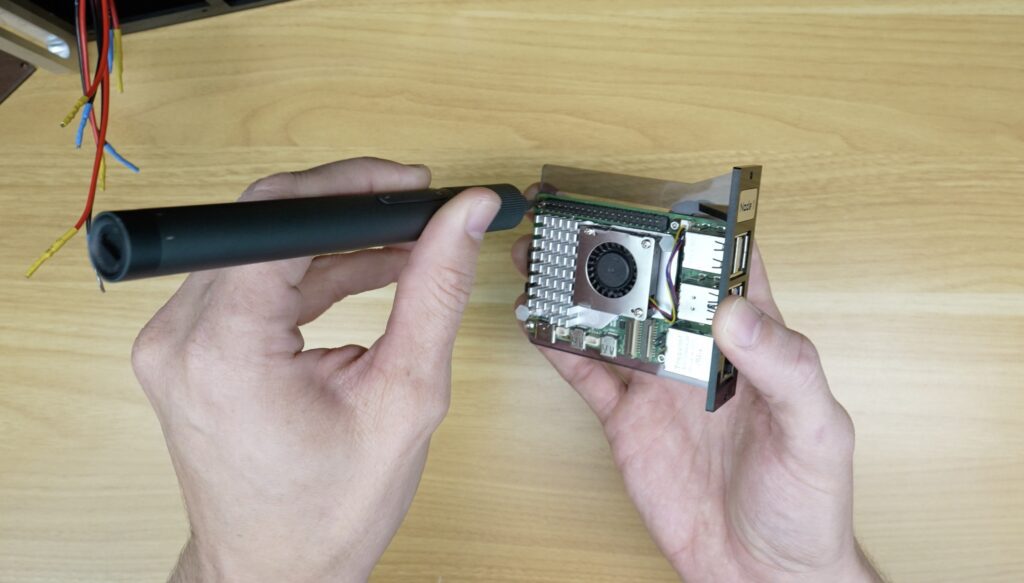
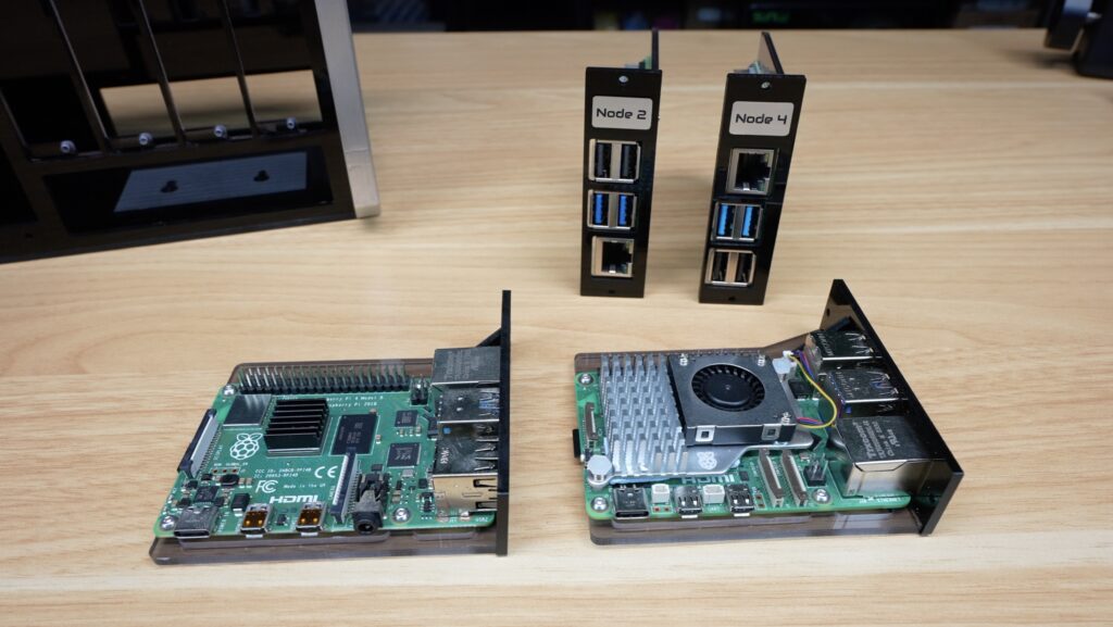
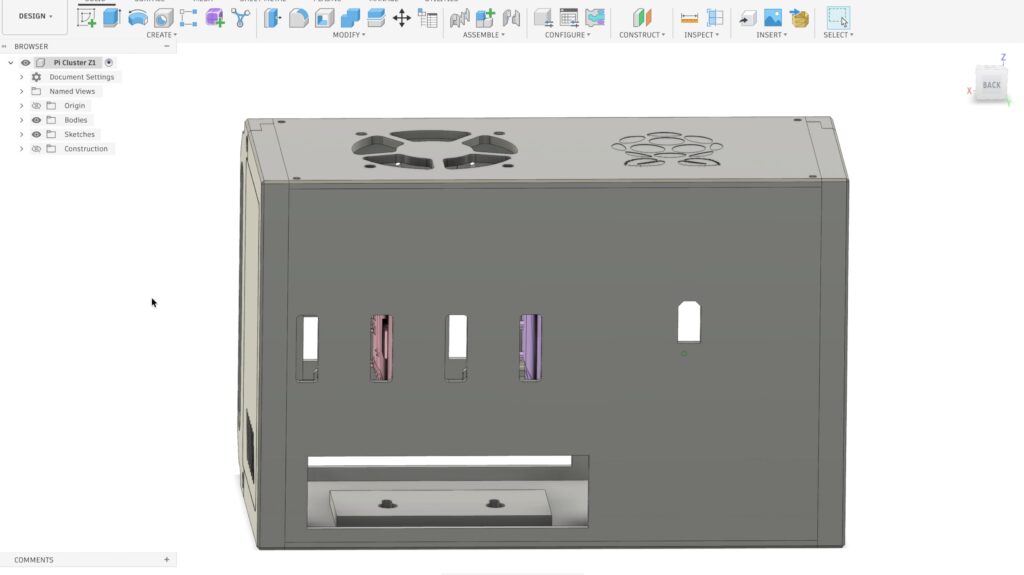
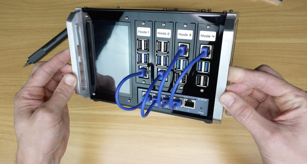
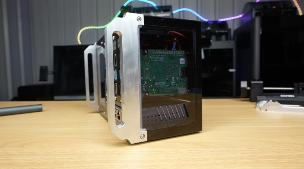
The Ethernet and USB ports all face forward to plug into the network switch, and the microSD cards remain accessible through cut-outs on the back panel. This means I can swap operating systems or update individual nodes without dismantling the cluster.
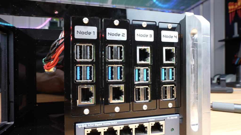
The switch mounts underneath the nodes. Four ports on the switch below connect the nodes together, and the fifth is left available so the cluster can connect to the rest of my network.
Alongside node 1 goes the IPS touch display, which is held in place with four M2.5x6mm screws. It connects to the node 1 Pi alongside it with a DSI ribbon cable.
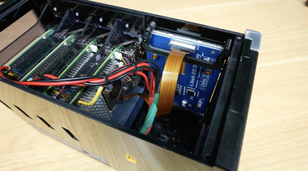
A single 5V 60mm fan on the top panel provides cooling to the four Pi’s beneath it. This is powered by one of the Pi’s beneath it through its GPIO pins. It doesn’t matter which one since the fan isn’t PWM controlled.
The top panel can then be closed up with the M2.5 screws in the corners. These holes need to be drilled and tapped into the acrylic enclosure. I’ve tried adding these during CNC cutting previously, but with mixed results. They usually land up in the wrong place due to the combination of tiny manufacturing inaccuracies and slightly misaligned glue joints.
And that’s the hardware complete.
Creating The Cyberpunk Themed Stats Display
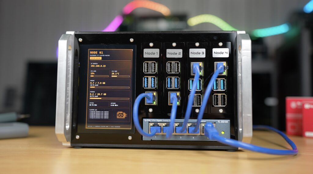
For the display, I created a custom cyberpunk-inspired dashboard running in Chromium kiosk mode which opens up automatically on startup.
The display shows information from node 1 including system load, storage usage, memory utilisation, network information and some other live statistics.
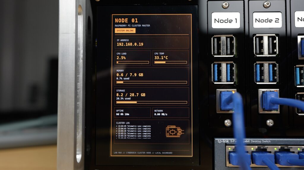
It doesn’t just make the cluster easier to monitor, it also acts as a mini control panel. It’s a full touch display than you can use to do anything you’d usually be able to do on the Pi desktop, albeit a bit small.
You can also set it up to provide summary stats for all four nodes or cycle through pages for each node if you’d like to.
Final Reveal & Thoughts On The Compact Raspberry Pi Cluster
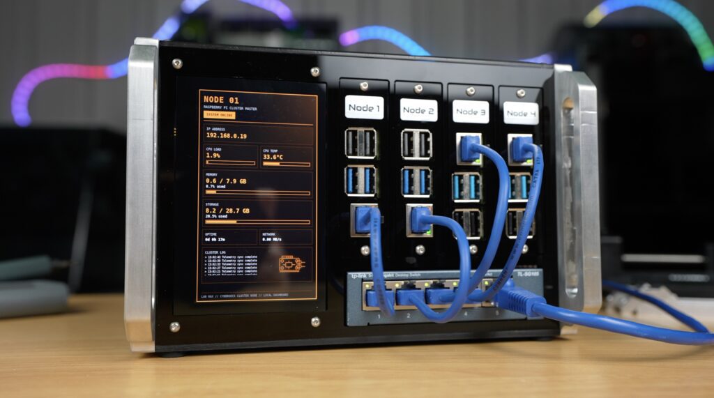
So here’s the final build. We’ve got the cluster of Raspberry Pis in a compact acrylic enclosure with networking and custom monitoring, and without a mess of cables.
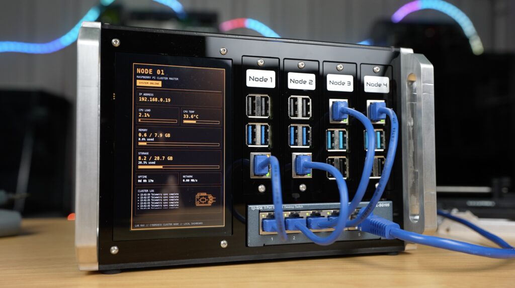
The tinted acrylic panels let you see the internal hardware, the aluminium accents add a bit of contrast to the black panels, and the display brings the whole thing to life.
A huge thank you to Makera for sending over the Z1 and the Cyclone Dust Collector Lite for this project. The Z1 has just been launched and is now available to order. Check out the product page if you’d like to learn more about them or get one for yourself.
They’re also soon launching Makerables, a CNC project sharing platform for the community to share designs and files.
If you’ve got ideas for what I should run on this Pi cluster, then let me know down in the comments. Kubernetes? Docker Swarm? Or something completely ridiculous?
This setup would be great for Kubernetes because you can use the display to run the web dashboard and see resource usage and the pods you have deployed across the cluster.
Let me know what you think of the cluster and if you’d do anything differently in the comments section below.