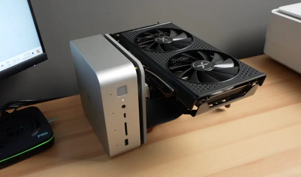
A couple of weeks ago, I tested the Beelink GTi 14 Ultra, a powerful mini PC with a full-size PCIe port underneath it. At the time Beelink said that this was for a dock that they were working on, which would allow an external GPU to be used with the PC, but it hadn’t launched yet. So I tested the interface using my own 3D printed adaptor that screwed onto the bottom of the pc along with a PCIe riser and an external power supply.
Beelink have now completed the dock, so that’s what Im going to be sharing with you in today’s video.
This is the EX Docking Station and it is compatible with the GTi14 and GTi12 series PCs at the time of writing this post.
Here’s my video of the EX Docking Station, read on for my write-up;
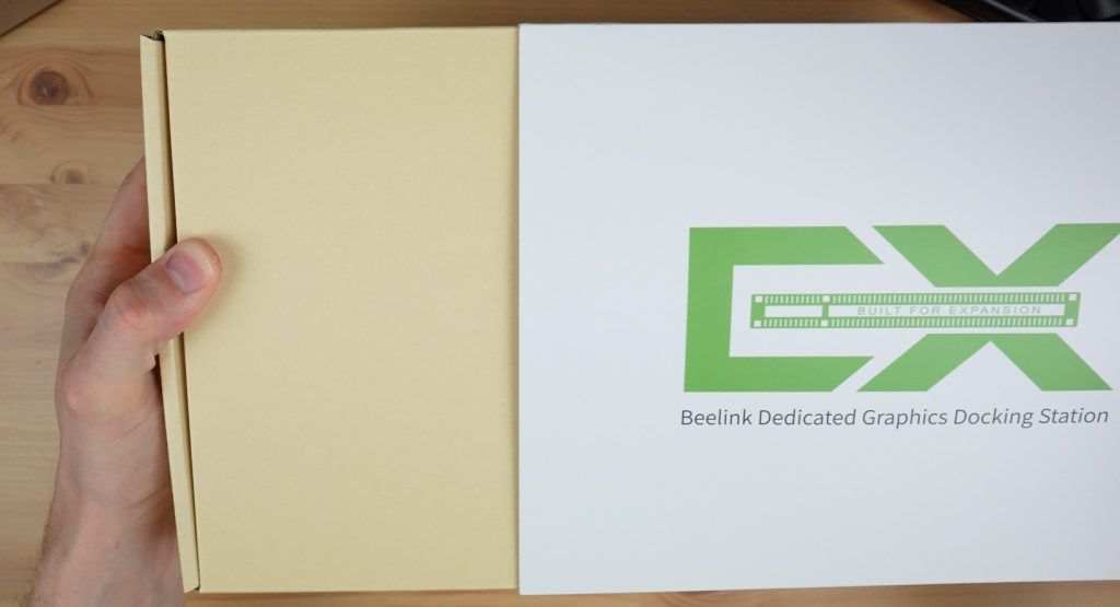
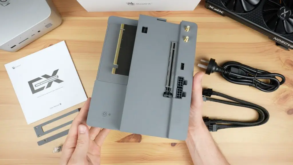
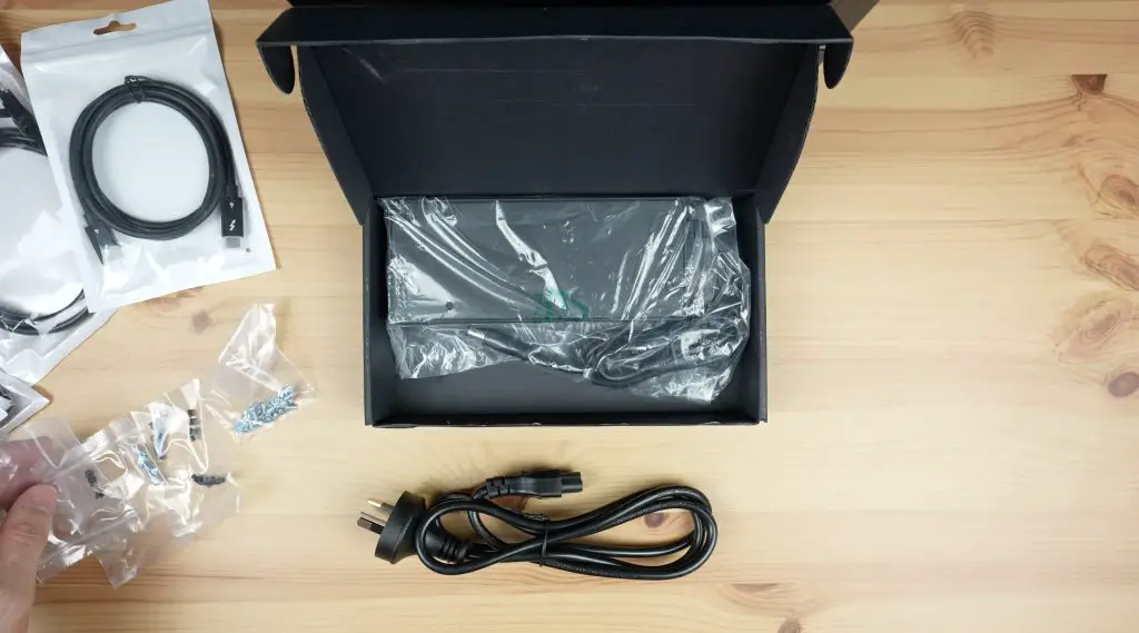
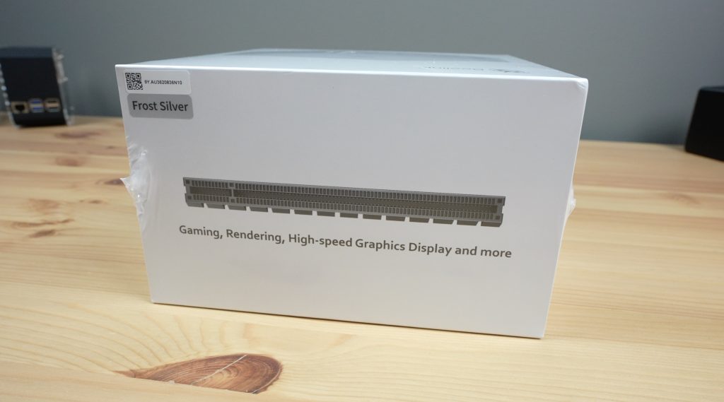
The Beelink EX Docking Station comes in a white branded-sleeved box that is a lot bigger and heavier than I was expecting it to be.
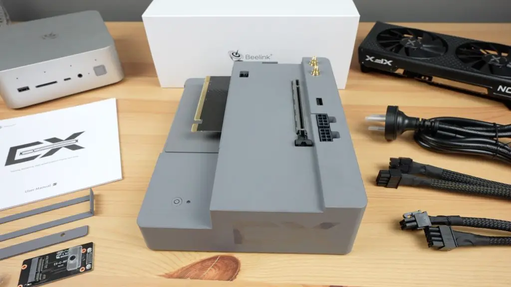
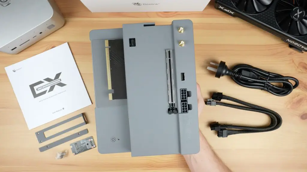
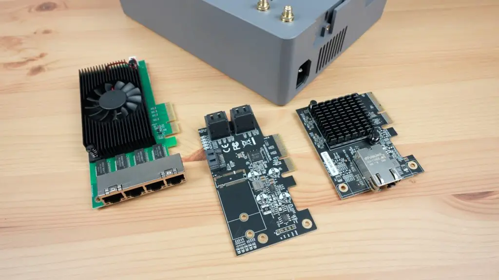
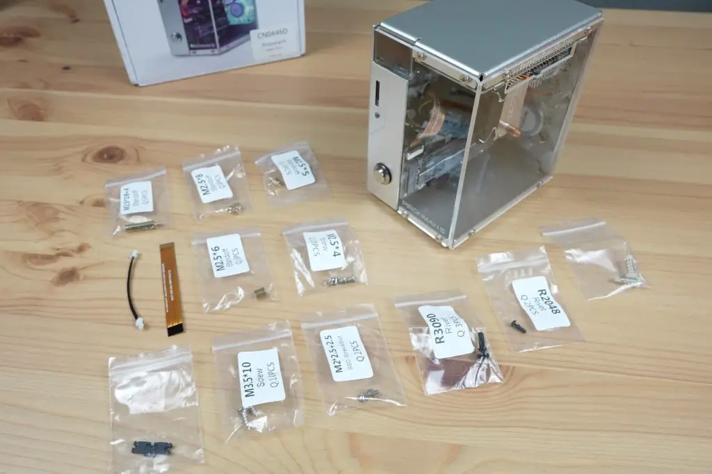
Inside the box you get some manuals, the EX Docking Station, 8-pin power connector cables, a power supply cable, brackets to hold the PC and GPU in place and then a pack of screws and a PCB that looks like an M.2 adaptor for a wifi module.
The EX Docking Station measures 179mm wide, 65mm high and 225mm long.
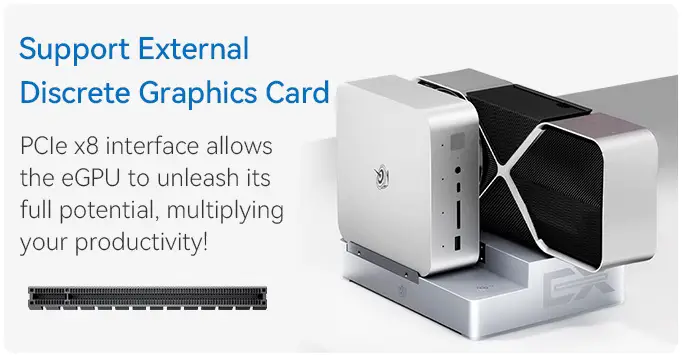
This is a bit more than just a PCIe adaptor or riser, Beelink have integrated a few other features which make it versatile and really easy to use.
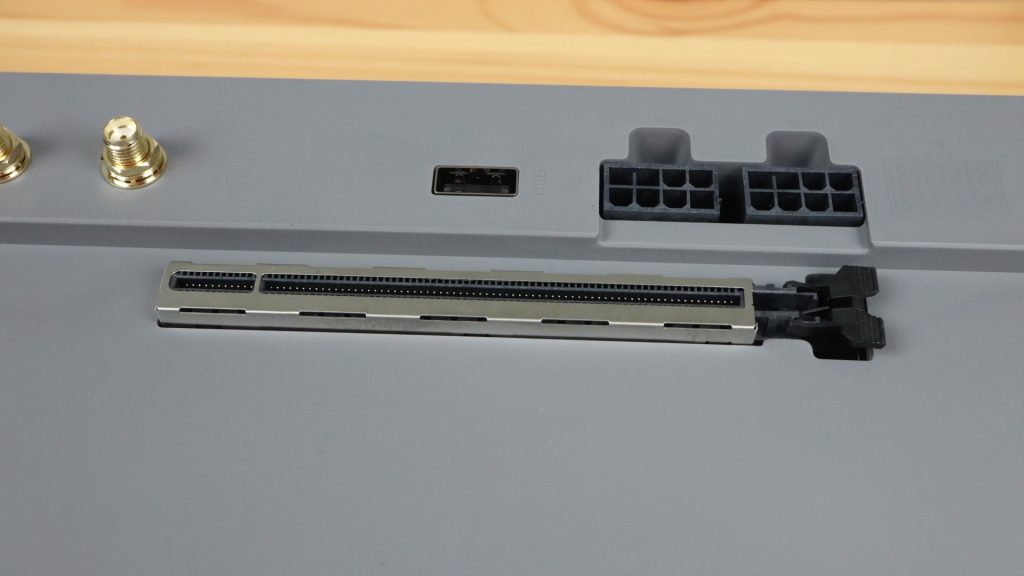
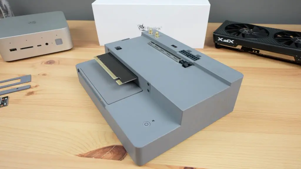
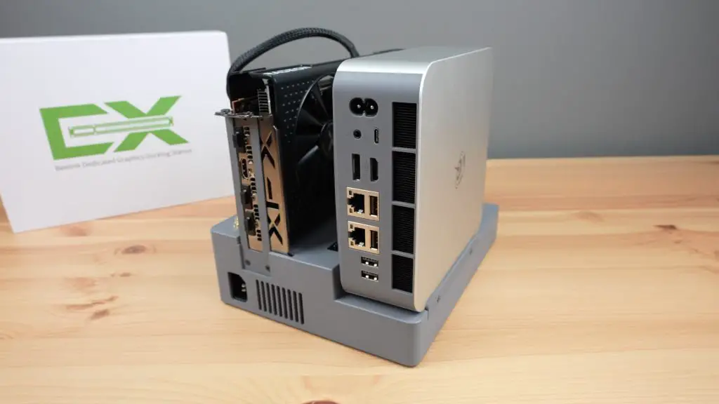
First up is the obvious main feature, the PCIe x8 port which allows you to connect an external GPU to the PC.
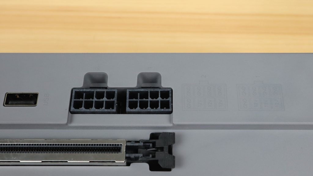
Alongside that are two 8-pin power supply ports for the GPU. These are fed from an internal 600W power supply.
There is also a separate port to power an external fan if your GPU requires this.
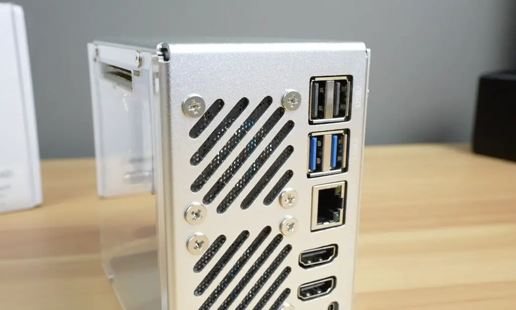
Next to those is a USB2.0 port. I think this is a bit of a strange addition, it would have been a lot more useful if it were a USB 3.0 port or USB type C port but I guess you could use this for a keyboard or mouse dongle.
Then there are two antenna ports that you can use if you add an internal WiFi adaptor.
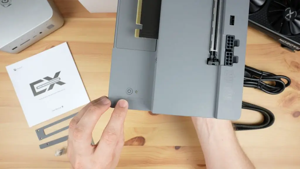
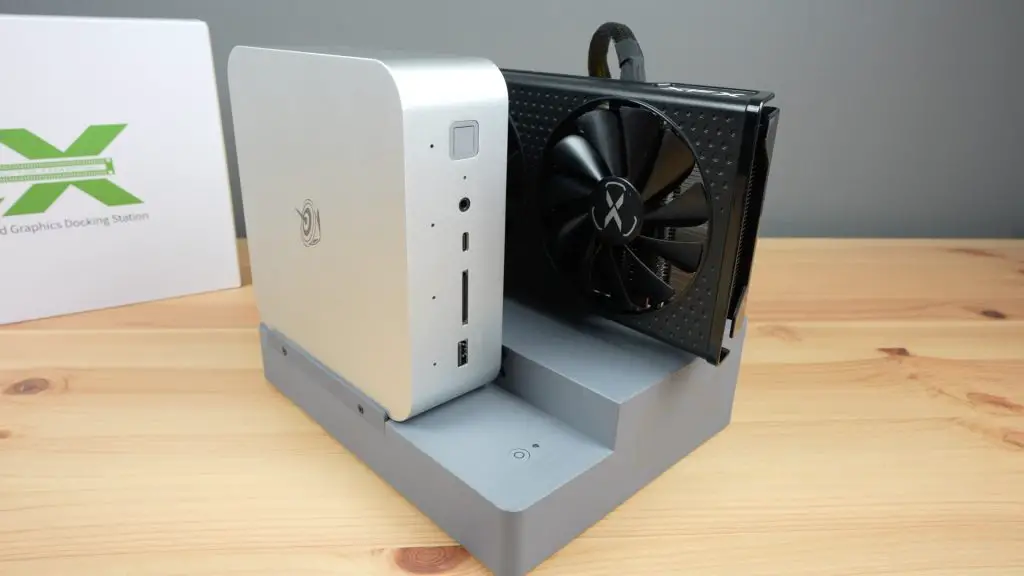
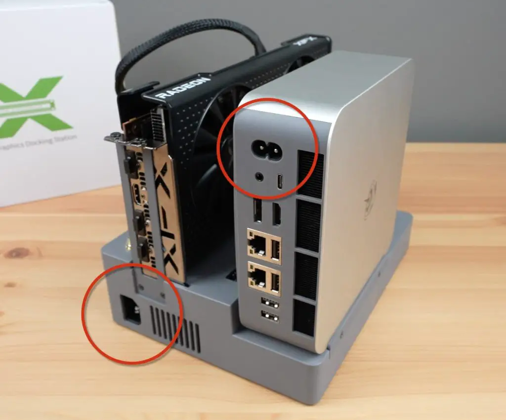
At the front is the power button and a power indicator LED alongside it.
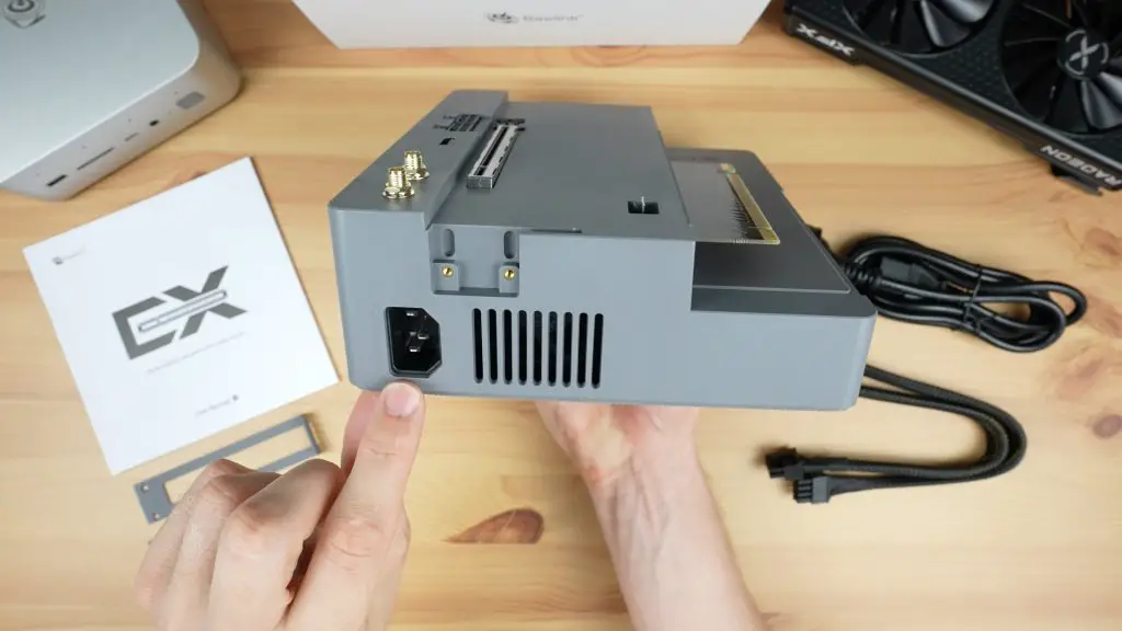
At the back, we’ve just got the power supply input and some ventilation holes.
What GPUs Can You Plug Into The EX Docking Station?
The open design and relatively powerful integrated power supply mean that you can use a high-end GPU with the docking station.
Beelink claim that you can run a GeForce RTX 4090 in it. I don’t have a 4090 to test this claim, but it seems like they have sized the power supply at 600W specifically to make sure that high-end cards like these can be used since the 4090 requires around 450W. As shown earlier, the dock only has two 8-pin power ports available though and some cards like the 4090 require 4. So you may need to use additional adaptors to supply power to your card.
Another thing to keep in mind is that the dock is designed for 2-slot cards, so you’ll probably need to remove or not use the retaining bracket to use a 3-slot card like the 4090 but there looks like there is enough room for it.
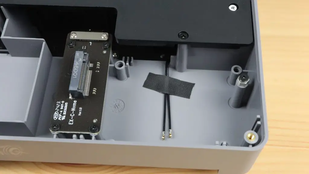
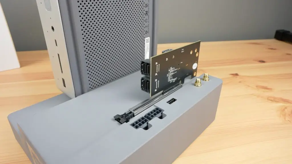
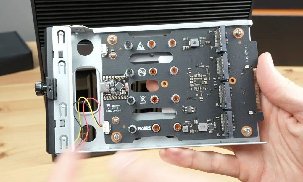
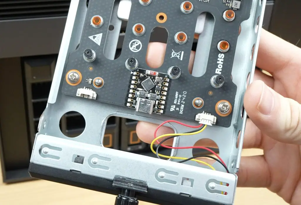
Internally, the EX Docking Station also has another PCIe 4.0 x 1 expansion port in the form of an M.2 port. You can use this port to add an NVMe SSD or use the small included adaptor board to add a WiFi module.
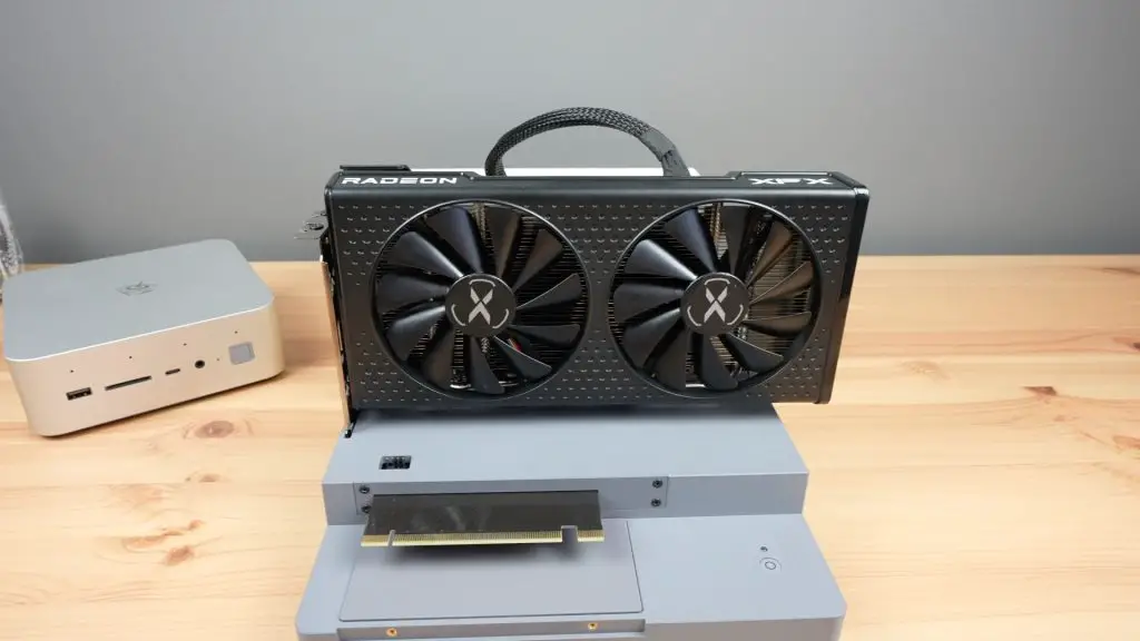
Installing A GPU On The Dock
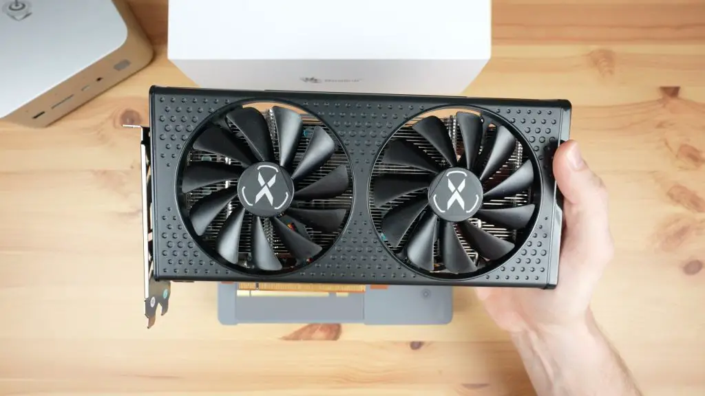
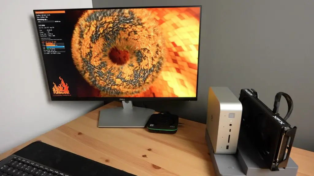
Now that we’ve had a look at what the EX Docking Station has to offer, let’s get a GPU plugged into it and try it out. I’m going to be using the same Radeon RX 6600 GPU that I used with my 3D-printed adaptor.
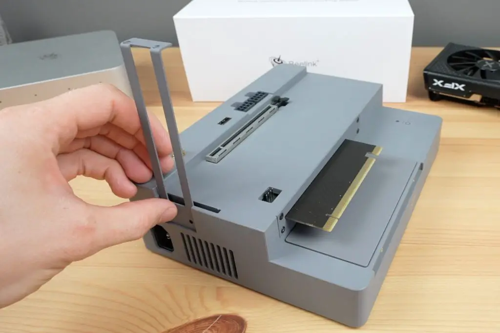
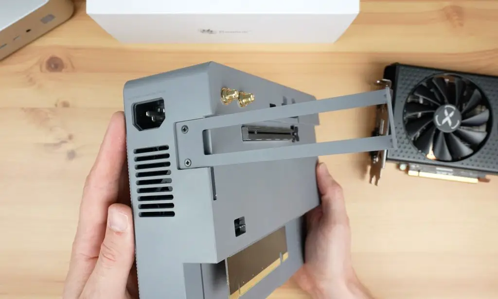
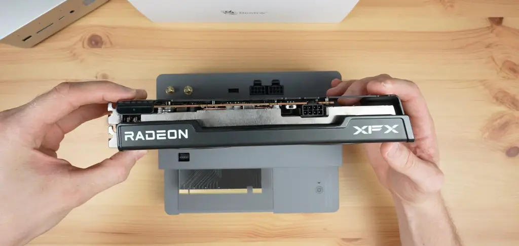
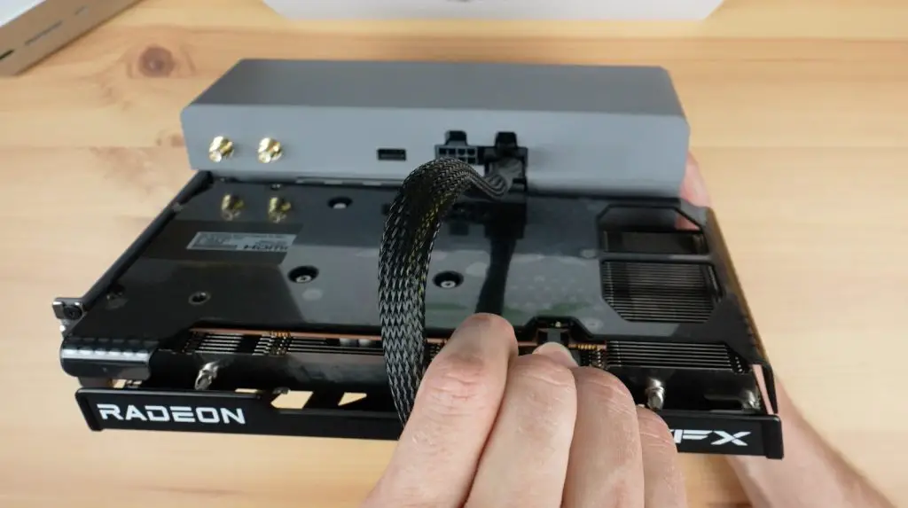
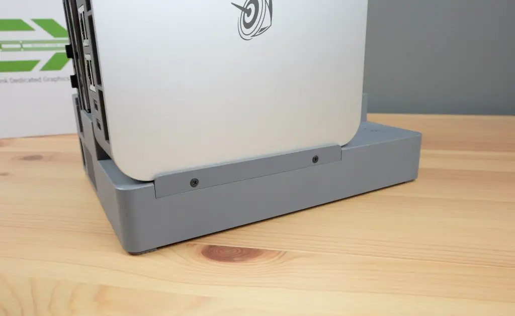
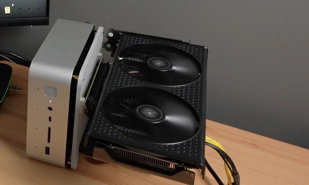
First, we need to install the mounting bracket on the back of the dock.
The GPU plugs into the PCIe port and we just need to hook a single 8-pin power cable up to it.
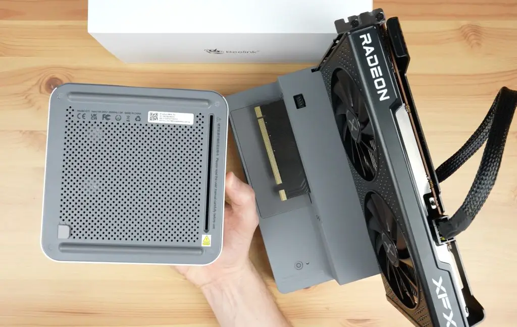
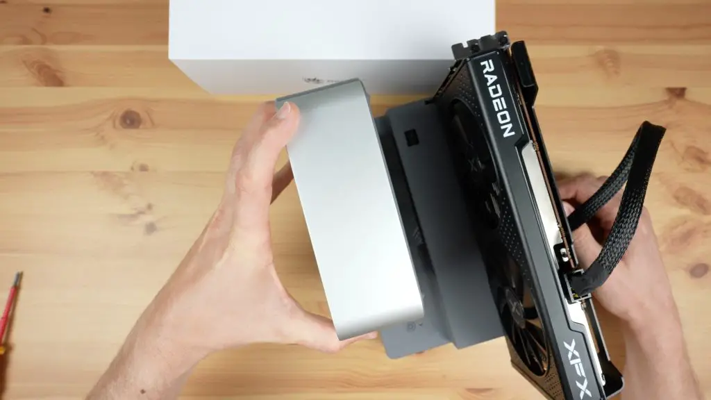
We then need to remove the cover over the PCIe slot on the bottom of the GTi 14 and then slide it onto the PCIe adaptor on the dock.
A retaining plate then holds the PC in place.
Testing The EX Docking Station
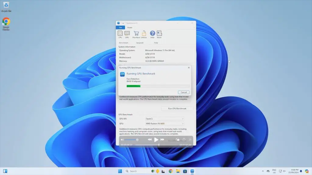
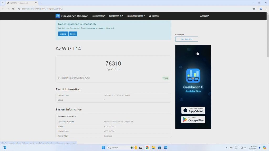
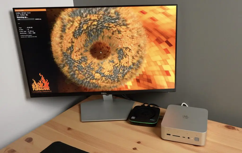
To test the EX Docking Station, I tried running two benchmarks that I ran previously on the stock GTi 14 – Geekbench GPU and Furmark.
In Geekbench we get a GPU score of 78,310, which is unsurprisingly significantly higher than the 37,460 we got on the stock setup.
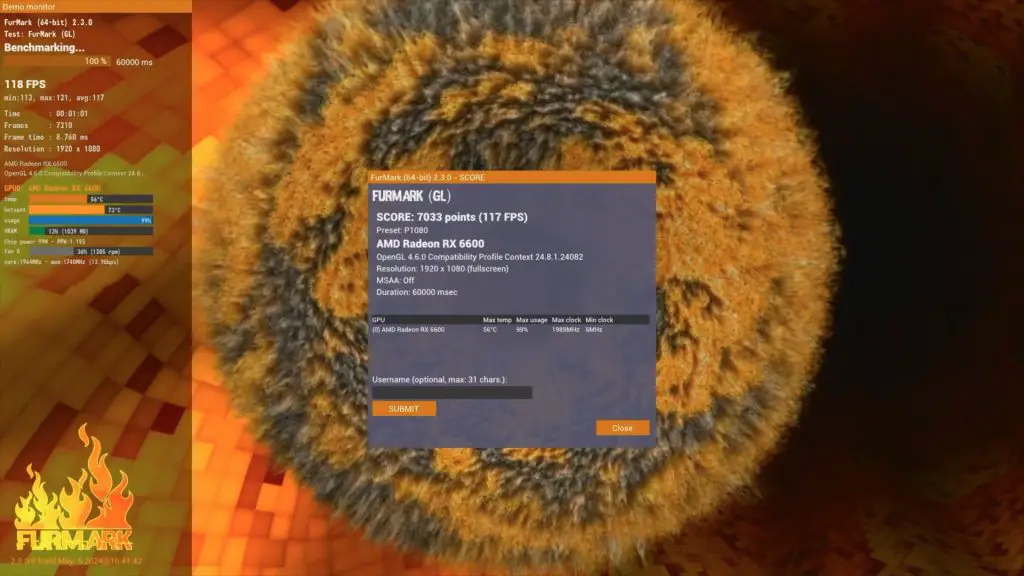
Running Furmark, we get a score of 7,033, which is also much higher than the 1,920 we got with the stock setup.
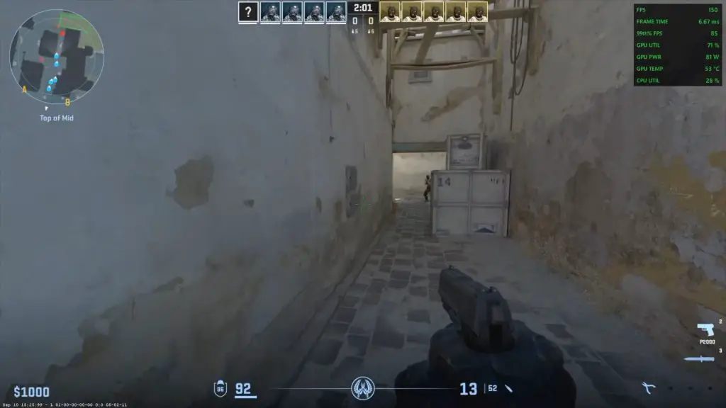
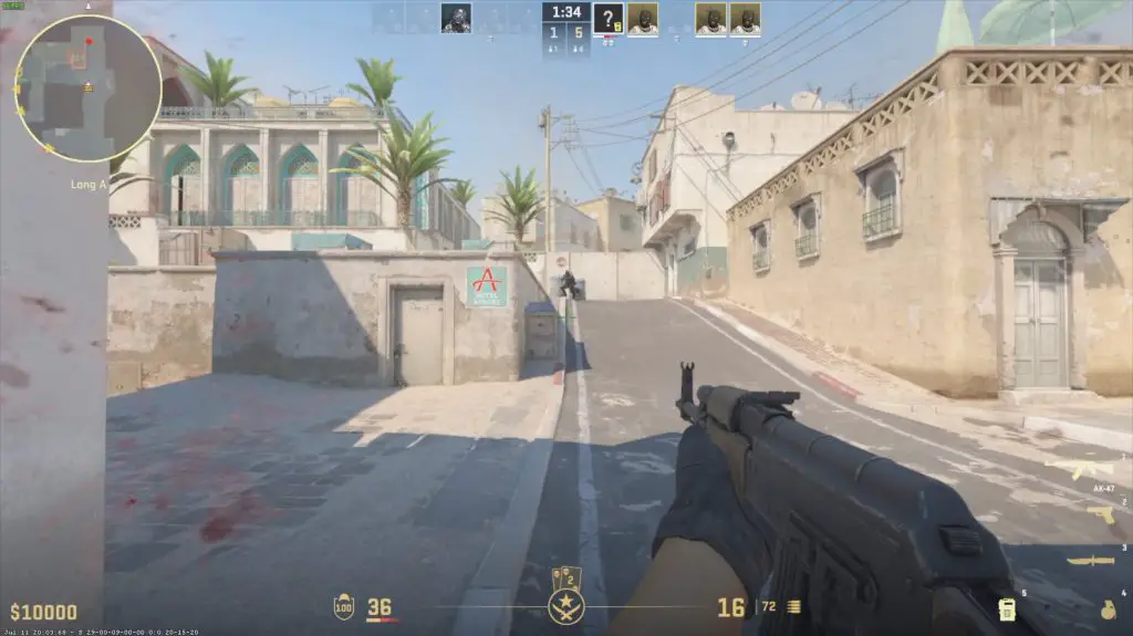
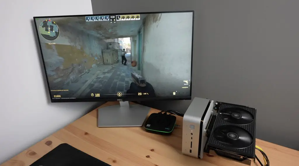
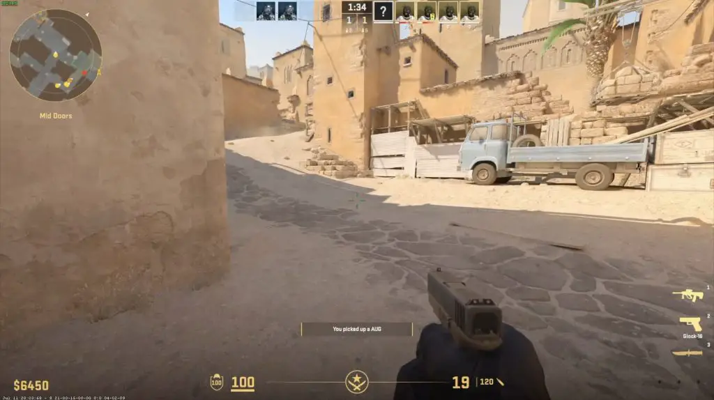
To test gameplay, I opened up Counterstrike 2 and set all of the graphics settings to Very High at 1080P.
We get around 150 fps quite consistently. This is about 2.5 times what we’d get on the integrated GPU, which is already quite powerful for a mini PC.
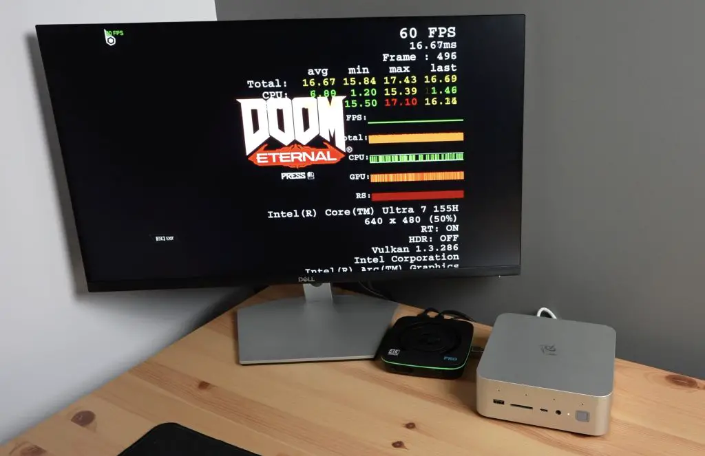
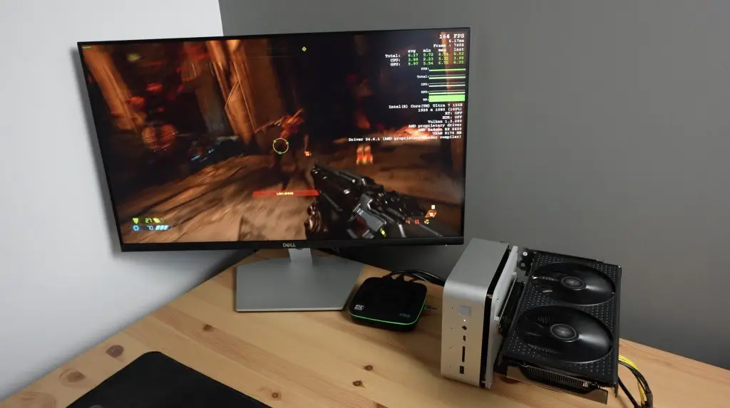
In Doom Eternal with all graphics settings on Ultra Nightmare and Ray Tracing turned off at 1080P, we get over 200fps. This is about 3 times faster than the integrated GPU and the RX 6600 is a pretty low-tier budget GPU.
Can You Use Other PCIe Cards With The Dock?
You don’t have to use this docking station to add a GPU to your PC. Since it uses a standard PCIe interface, you can use it with other PCIe cards too.
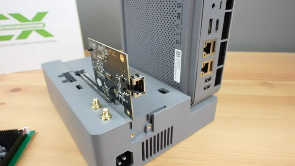
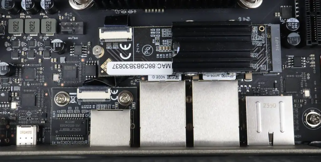
I actually used this dock to add a 10G Ethernet adaptor to the GTi 14 recently to do my testing on the Zimacube Pro and the TerraMaster F8 SSD Plus. This is obviously quite an expensive way to add 10G Ethernet to your PC, but it does give you a lot of expansion options for other cards too.
Final Thoughts On The Beelink EX Docking Station
The EX Docking Station retails for $159 on their website at the time of writing this post. You are paying a premium on what is largely a 600W power supply and a PCIe riser with some added features, but I don’t think it’s prohibitively expensive.
Being a first-gen product there are two minor drawbacks that I’d like to mention.
When you use the docking station with the GTi 14 Ultra, you still need to use a power cable for the PC as well. You’ve then got two power cables to plug in and two power buttons to press to boot the PC up. It would have been nice to have these a bit more integrated in some way.
I also would have liked to have seen an easier way to add and remove the PC from the dock. Something like a toolless lever or snap-in lock to hold the PC into place like a laptop dock would make it far easier to remove the PC, which is kinda of the point of a dock.
Other than those two drawbacks, I think this is quite an innovative product. Mini PCs have always been held back by their GPU performance and with this dock, you can add a high-end GPU to an already powerful mini PC to create a good gaming setup that also offers the flexibility to be very portable when you need it to be.
Let me know what you think of the dock in the comments section below.
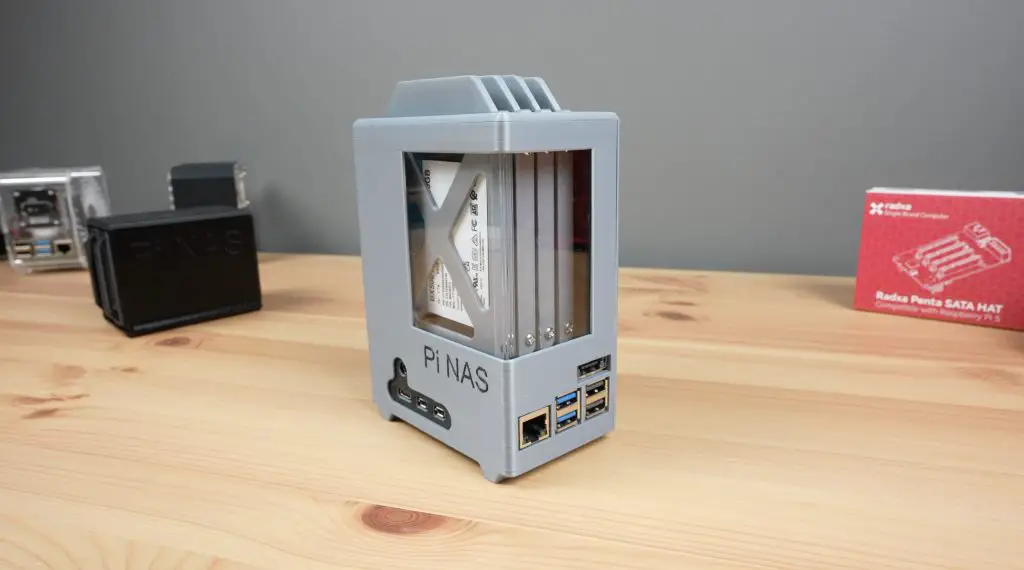
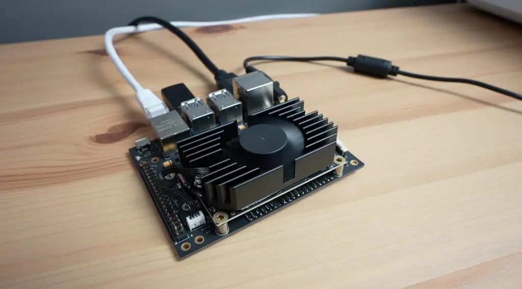
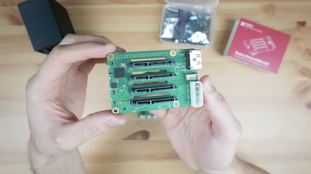
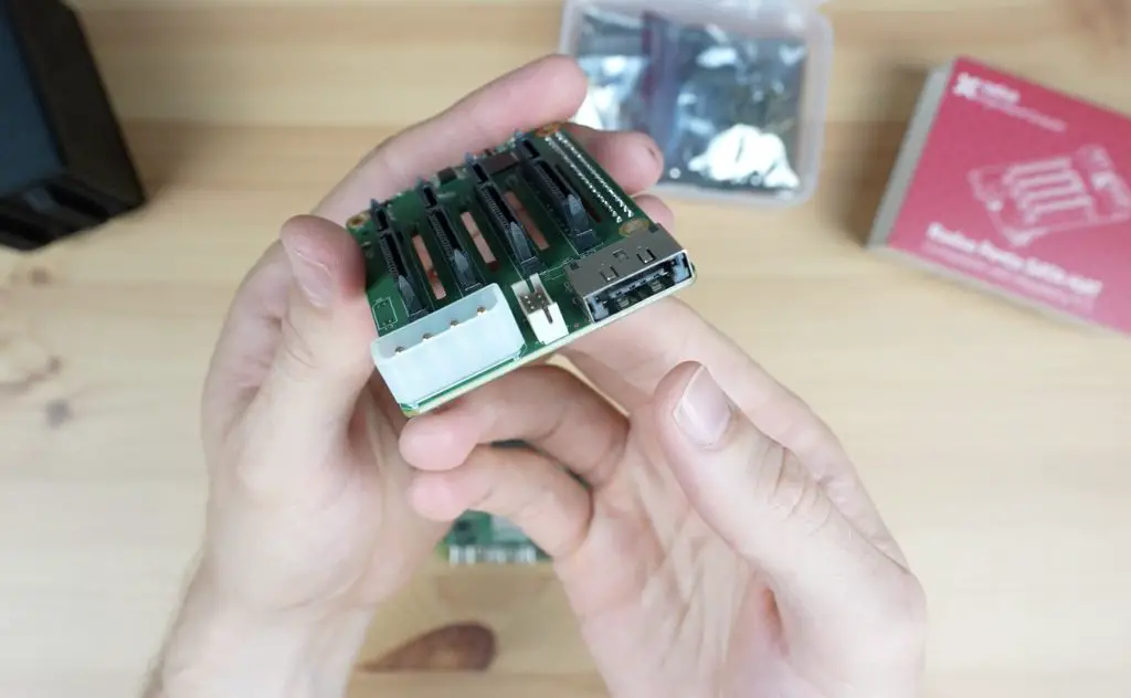
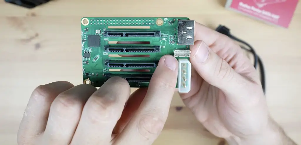
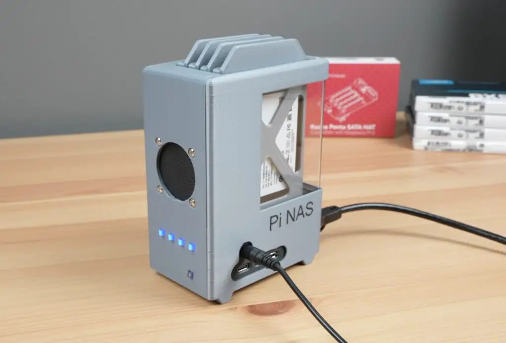
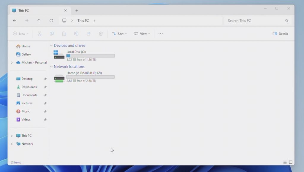
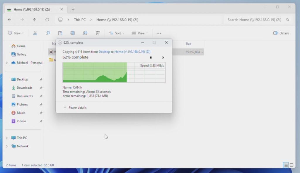
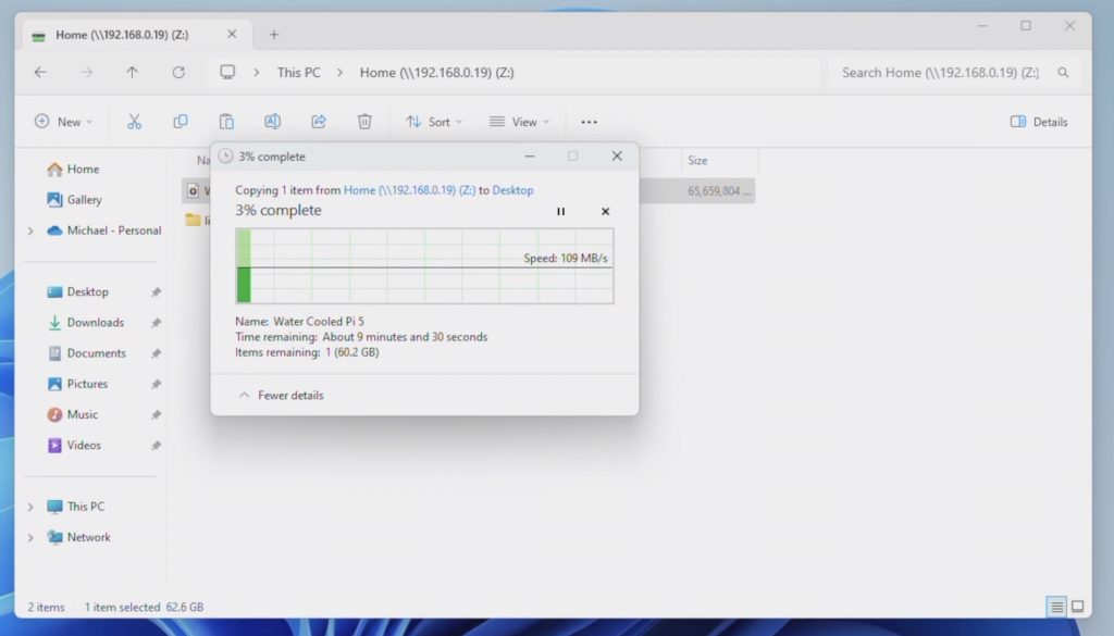
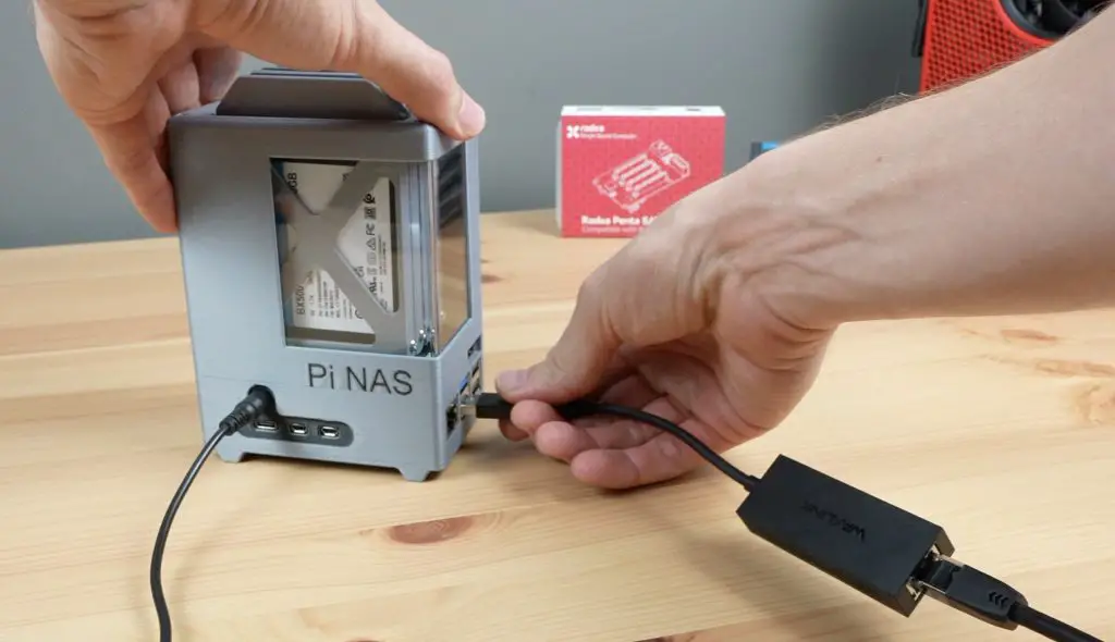
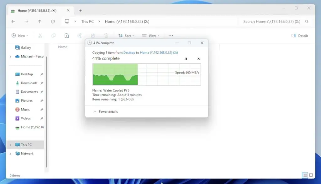
A few months ago I built an all-SSD NAS using a Raspberry Pi 5 and a quad-SATA hat from Radxa. By adding a 2.5Gb Ethernet adapter, I managed to get pretty good transfer speeds out of it. I got about 260MB/s writing files to the NAS and 200MB/s reading files from the NAS.
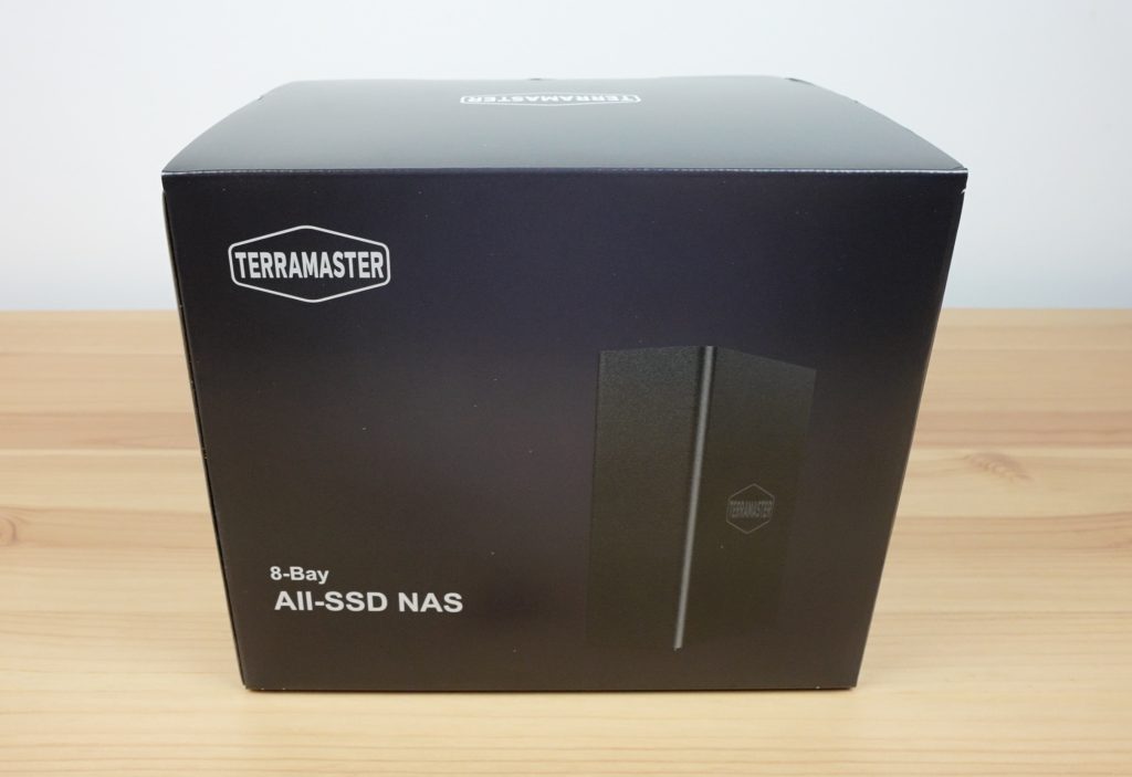
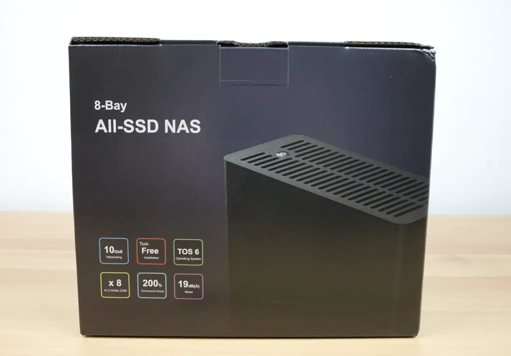
Following that video, TerraMaster reached out about a new all-SSD NAS that they’re launching this week. This is the new F8 SSD Plus. It’s their first NAS that is designed to be used with SSDs only and internally it’s got space for 8 M.2 NVMe drives.
There are two versions of this NAS. I am testing the higher-end F8 SSD Plus, which has an i3 processor and 16GB of RAM and will retail for $800. They also have a lower-spec F8 SSD with an N95 processor and 8GB of RAM for $600.
Here’s my video review and testing of the F8 SSD Plus, read on for my write-up;
Some of the above parts are affiliate links. By purchasing products through the above links, you’ll be supporting this channel, at no additional cost to you.
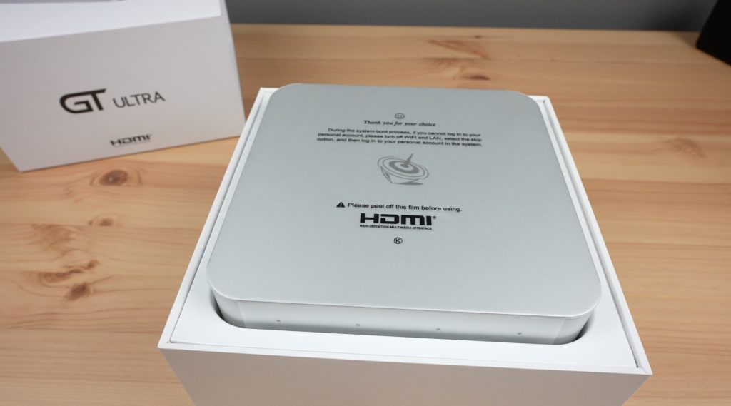
Unboxing & First Look At The F8 SSD Plus
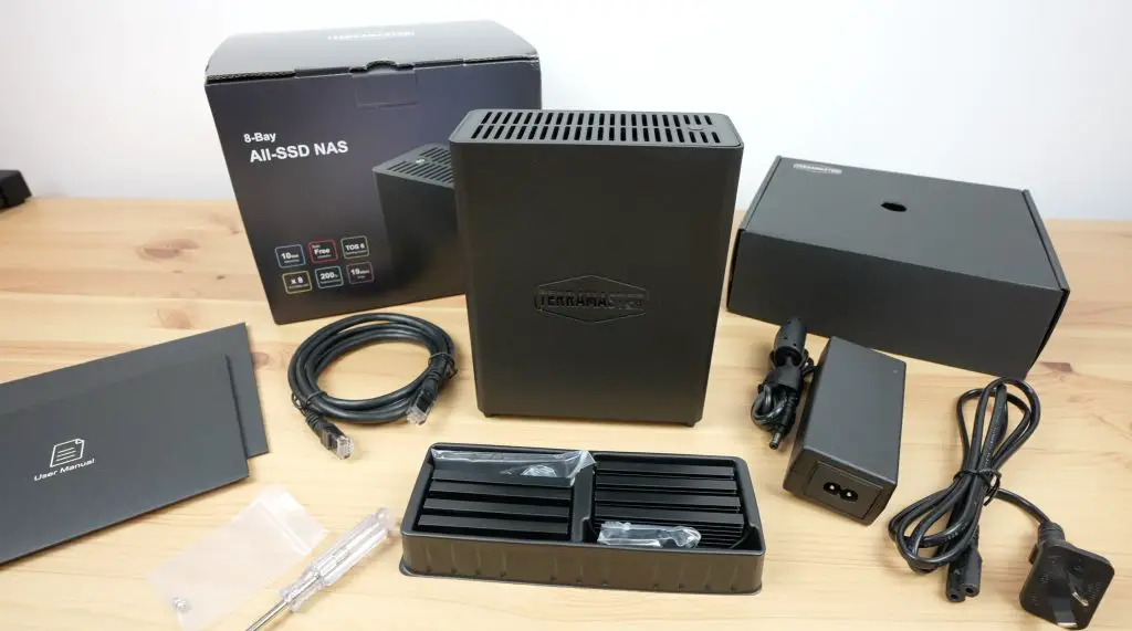
The F8 SSD Plus comes in a black branded box that already gives you the impression that this NAS is much smaller than a traditional NAS that takes physical drives.
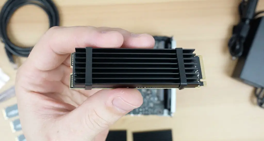
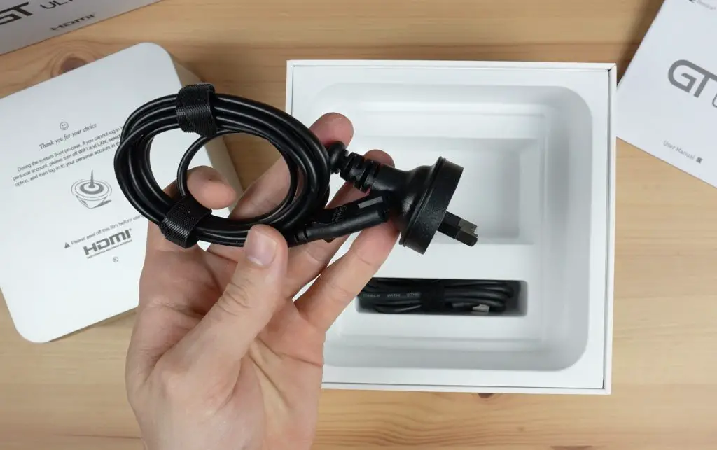
Included in the box is the F8 SSD Plus along with a Cat6e Ethernet cable, although not a particularly long one, a power cable for the power supply, a screwdriver and screws for installing the NVMe drives, the power supply and a set of 8 heat sinks for the drives. This is quite a nice inclusion which I wasn’t expecting to see.
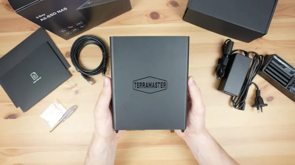
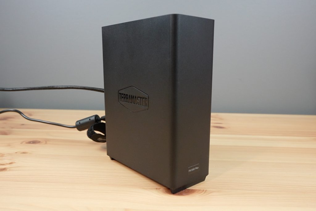
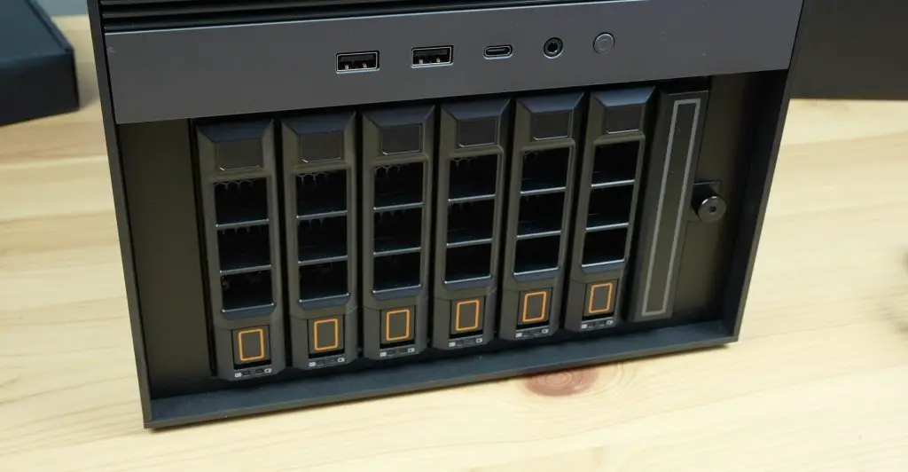
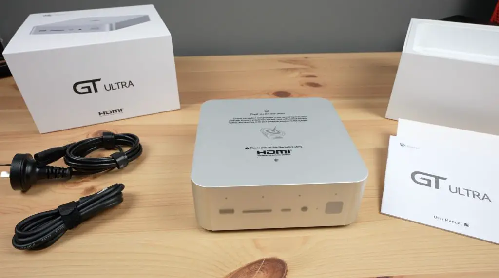
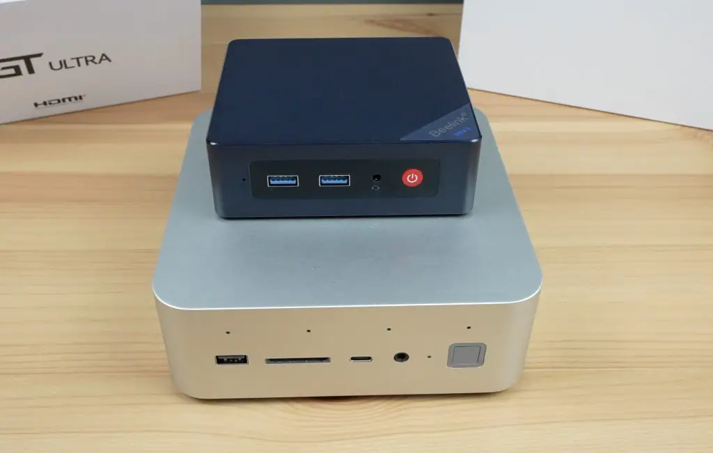
First up, this NAS is quite small. It’s not much bigger than a single physical 3.5” drive that a traditional NAS would use.
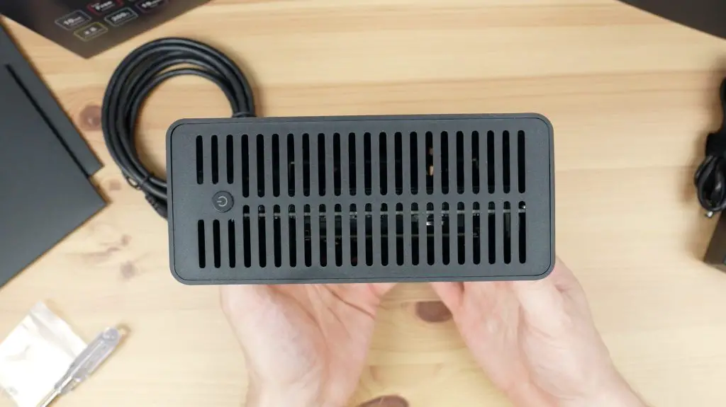
It’s a minimalistic design, which I quite like. There is nothing on the front and the two sides bear the TerraMaster logo.
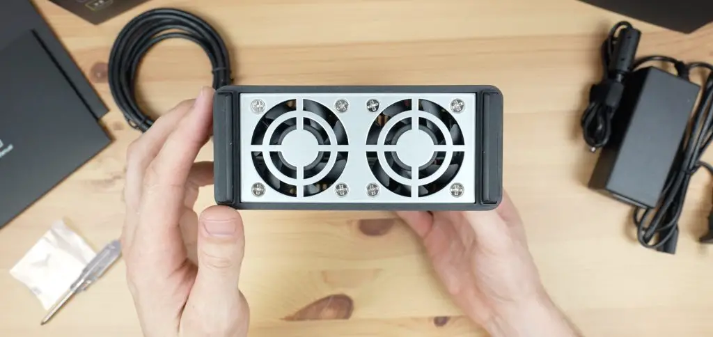
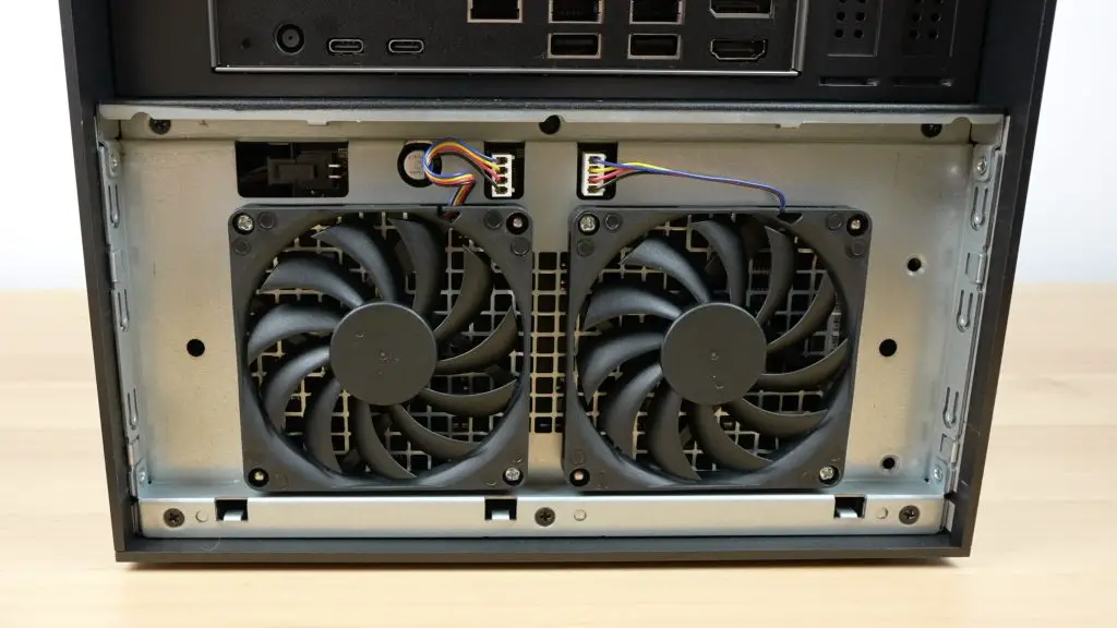
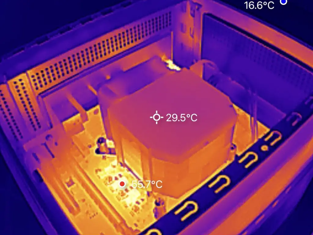
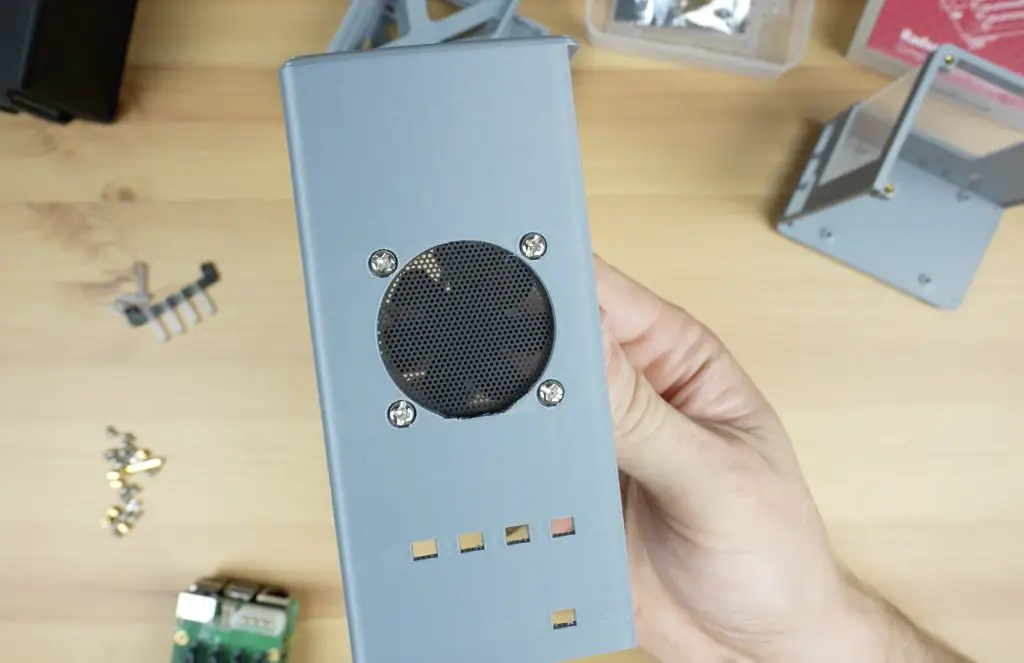
On the bottom, we’ve got two 50mm PWM fans which draw air in through the bottom and exhaust out of the top of the NAS.
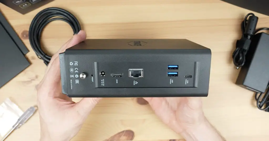
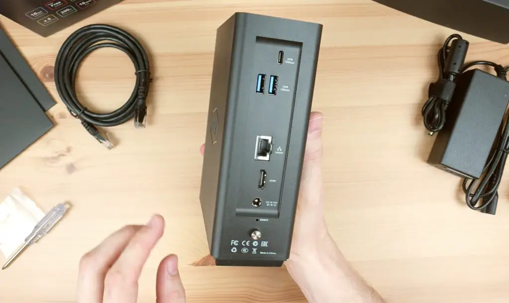
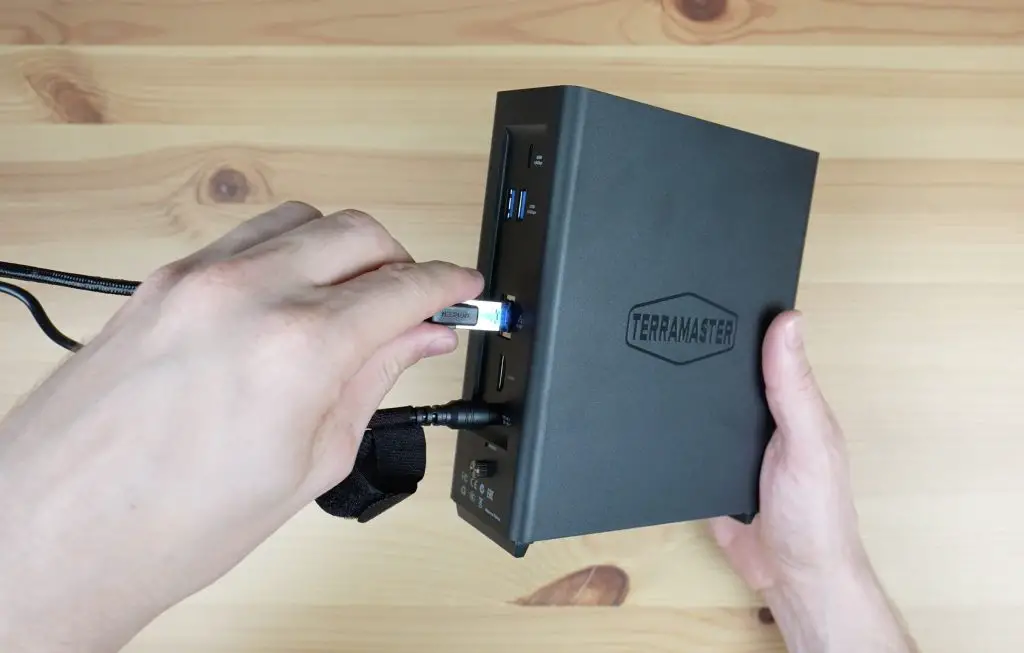
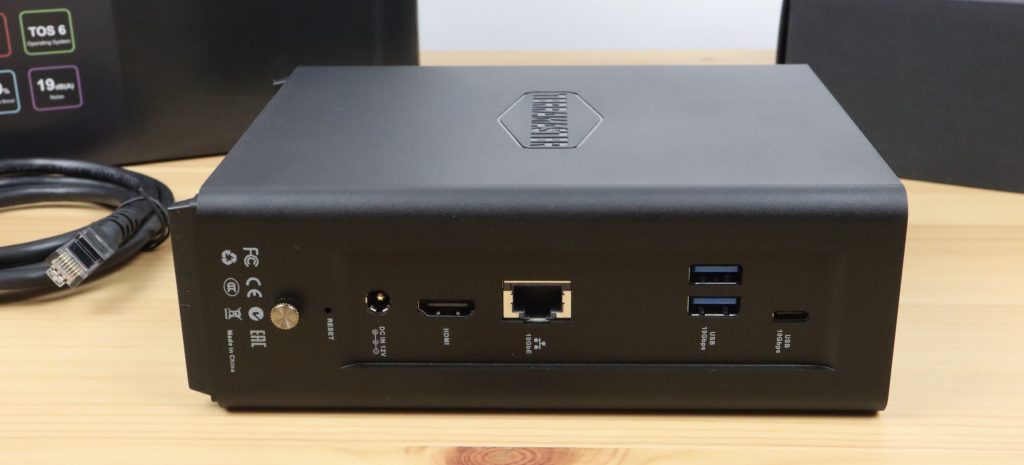
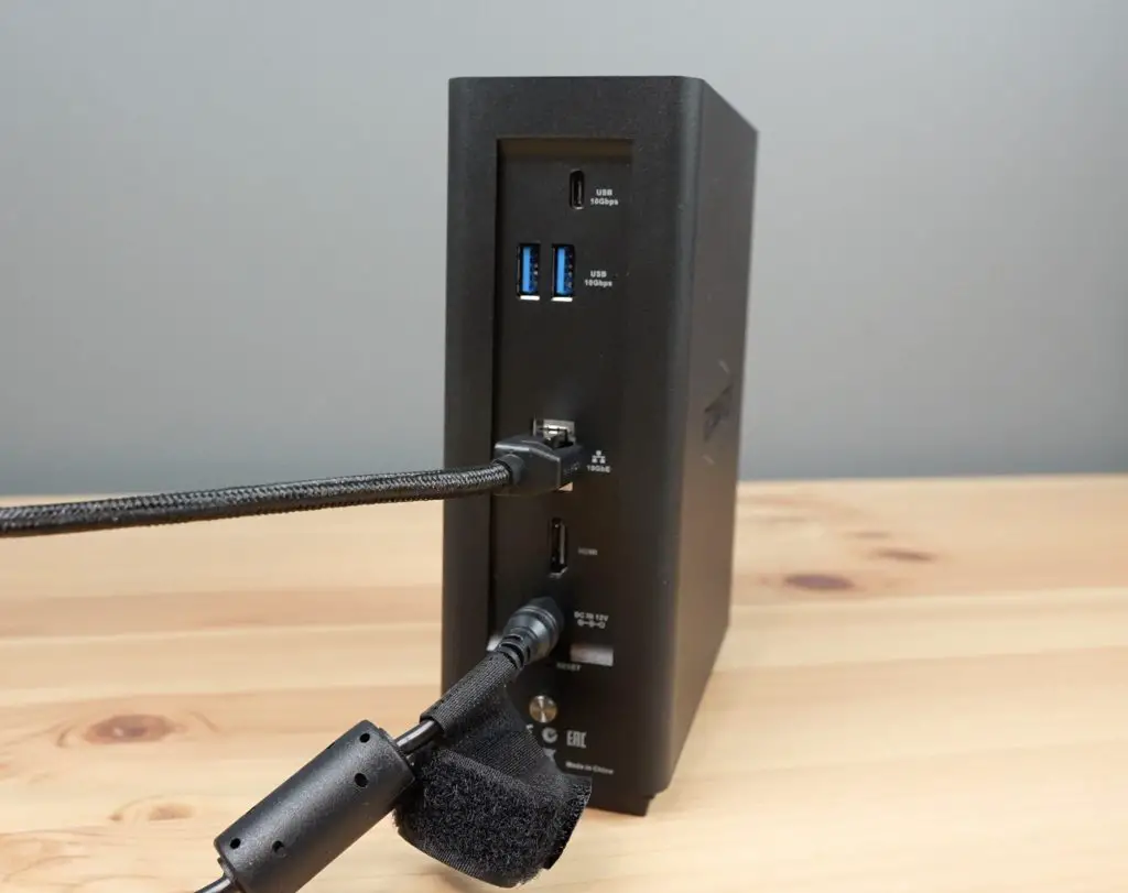
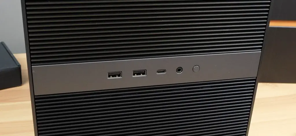
On the back, we’ve got the barrel jack power input, an HDMI 2.1 port, a 10Gb Ethernet port, two USB 3.2 ports and a USB type C port.
On the top, we’ve got some ventilation holes and the power button.
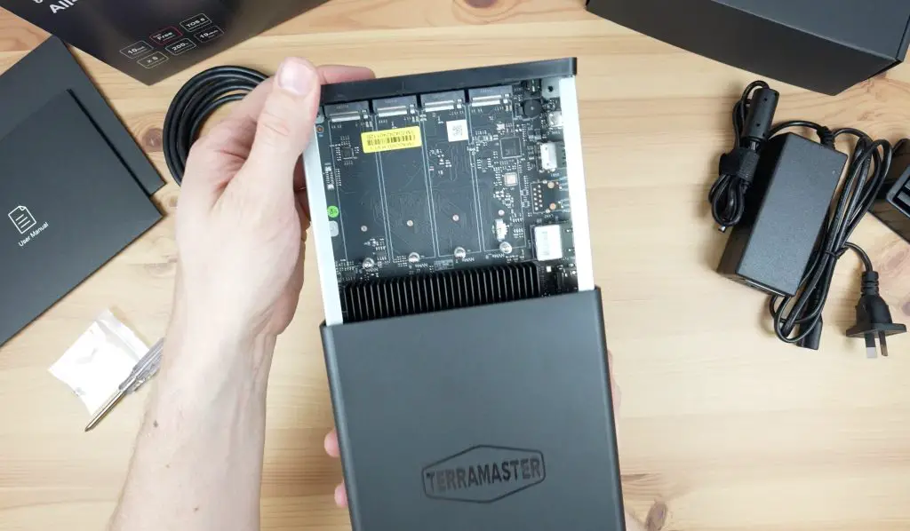
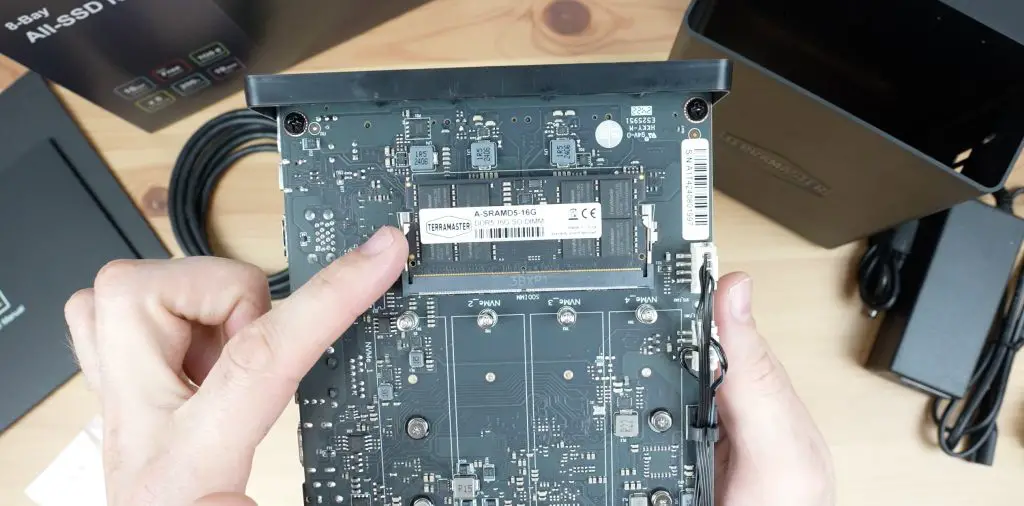
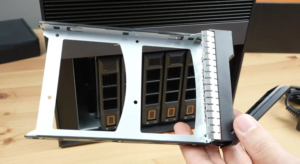
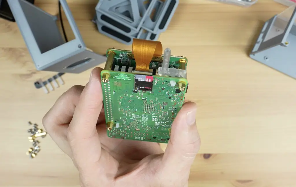
They say that this is a toolless design and it certainly is to open it up, we’ve just got a single thumb screw at the back. This allows the internal chassis to slide out to access the board and drives. I wasn’t sure whether the board slides out of the top or down and out from the bottom, but out from the top is the answer.
I think calling it a toolless design is a bit of a stretch as you need to secure your storage drives with a screw and they include a screwdriver for that. There are some ways they could have made it truly toolless but this is nitpicking, it’s not difficult to install the drives.
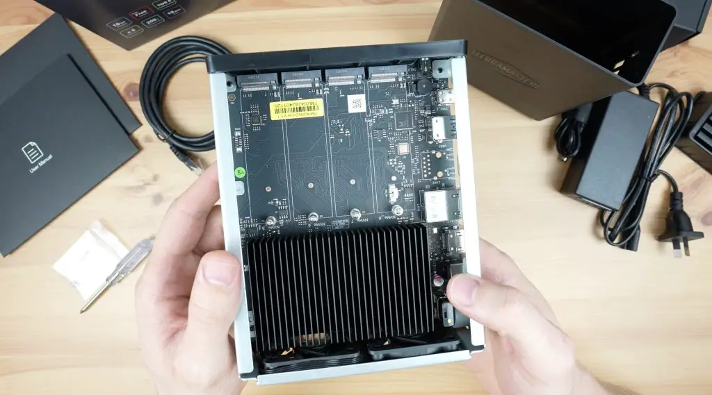
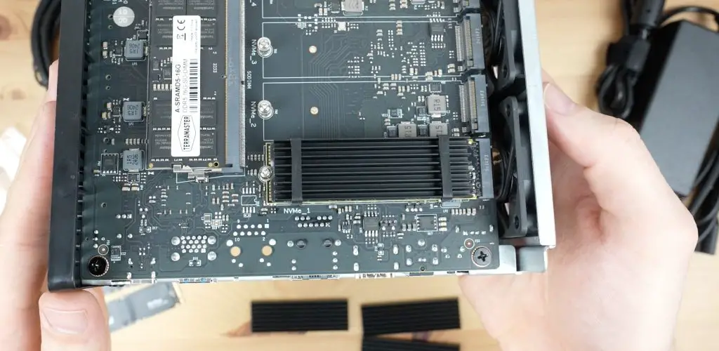
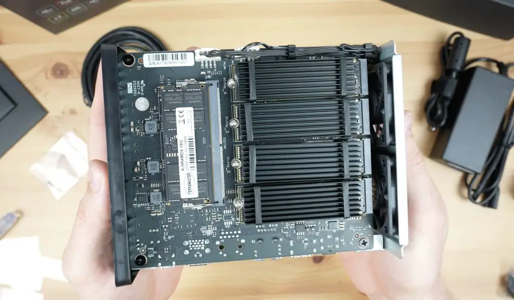
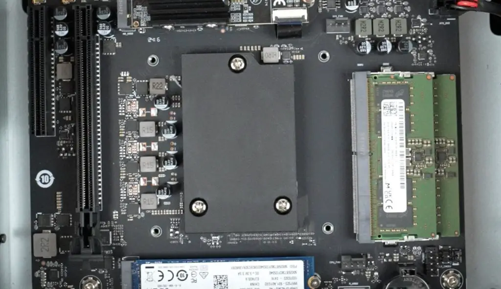
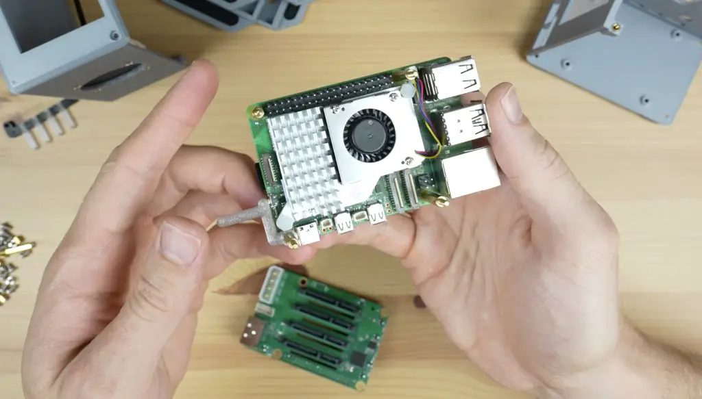
Internally we’ve got a single 16GB stick of DDR5 RAM running at 4800MHz. You can upgrade this to 32GB.
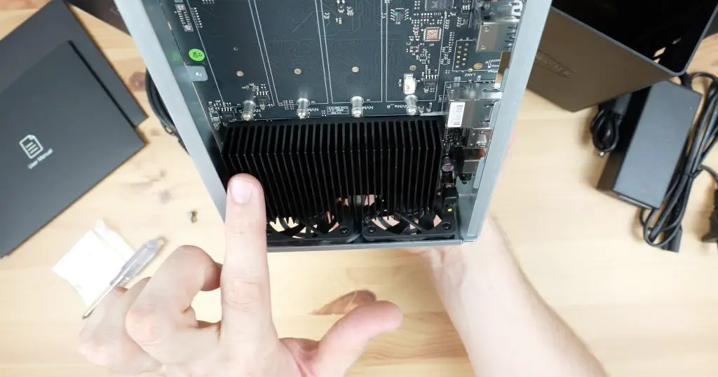
The CPU is under a large black heatsink at the bottom, directly above the fans. The F8 SSD Plus has an 8-core Intel i3 N305 processor with a maximum frequency of 3.8GHz. This is a 2023 chip which has got 6MB of cache and a TDP of 15W.
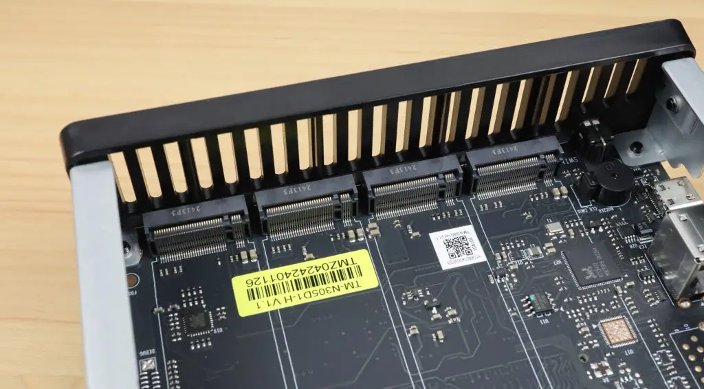
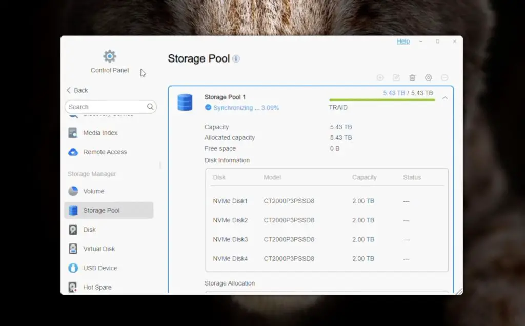
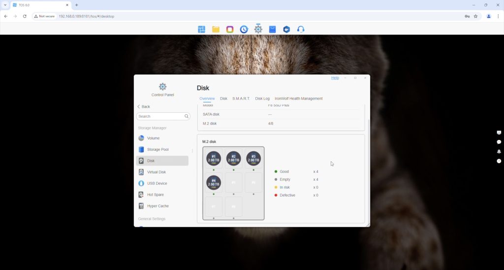
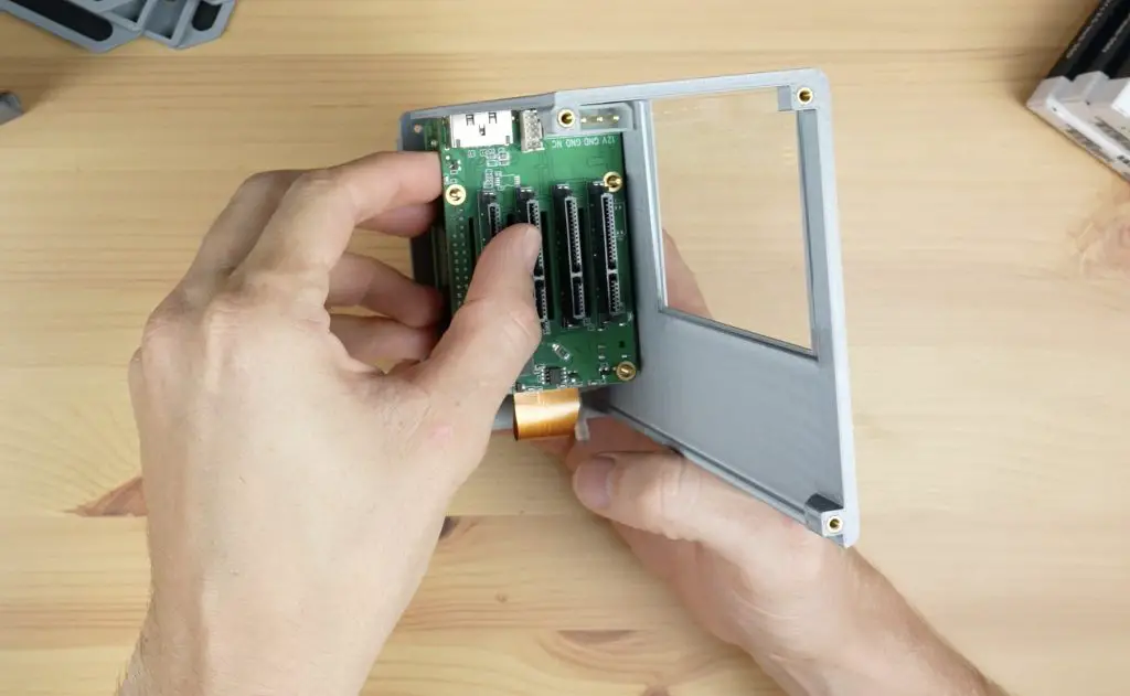
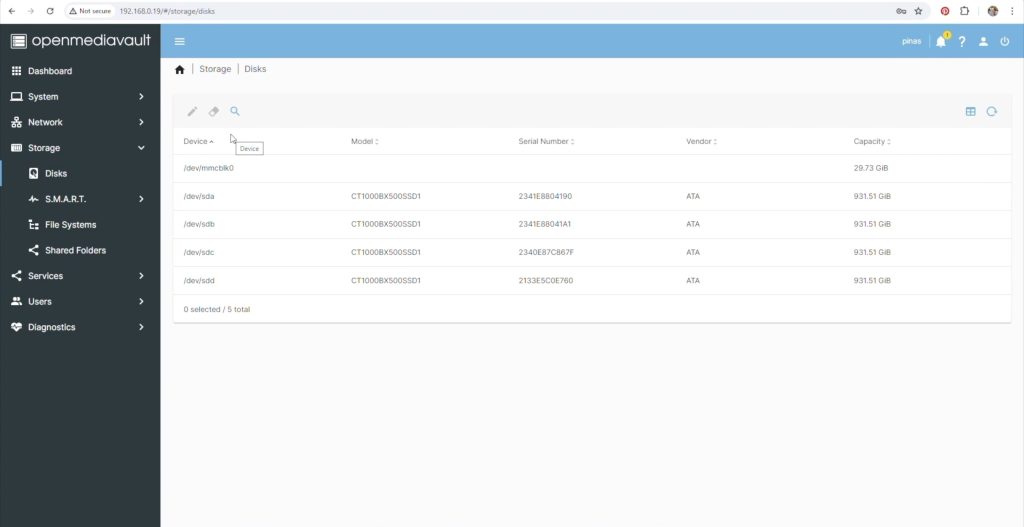
Then we’ve got our 8 M.2 NVMe ports. These are all PCIe gen 3 x 1 ports. This may sound disappointing at first glance, but each of these ports are individually capable of saturating the 10Gb network connection, so there shouldn’t be any issues with this speed. Through these 8 ports, we can connect up to 64TB of storage.
Installing NVMe Drives In The NAS
Now that we’ve taken a look at the internals, let’s get the drives installed.
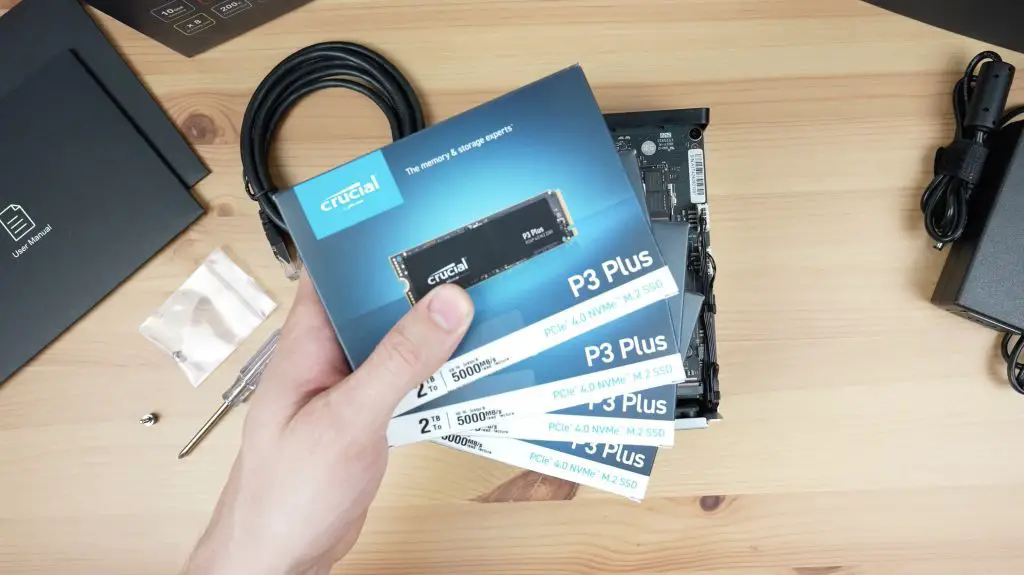
I’m using four Crucial P3 Plus drives. These are just for testing, if you’re going to be using drives in a NAS long term then you should get NAS-grade drives that have better endurance.
First, we need to fit a heatsink to each drive. They’re held in place with an included band on each end. I don’t particularly like this solution as I’m not sure how long these bands will last, but I do like that they’re fitted directly to the drive and the heatsinks look like they’re good quality.
Installing the drives is easy, they plug into the M.2 port and a single screw holds each drive in place.
With all four drives installed, we can slide the board back into the enclosure, plug in our power and network cable and boot it up.
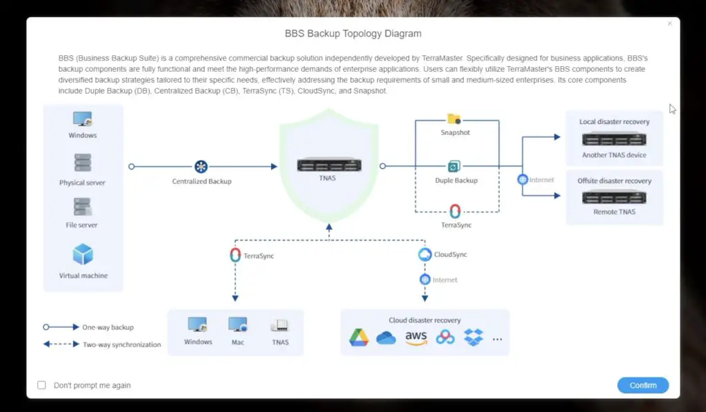
TerraMaster’s Lastest Operating System TOS 6
By default, the F8 SSD Plus is set up to install and run Terramaster’s latest operating system called TOS 6. It’s based on Linux but they’ve given the web interface a Windows 11 look and feel.
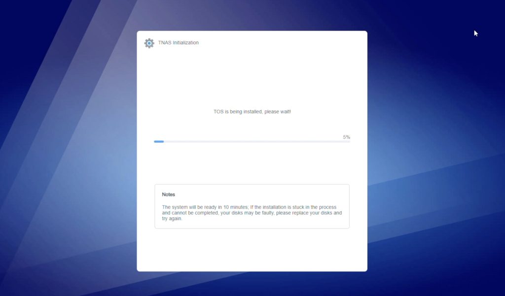
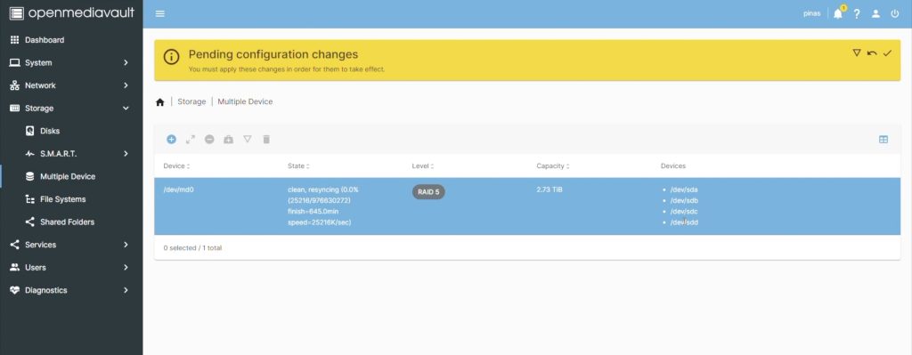
On the first boot, you’ll be guided through a setup process that will set up a drive pool and install TOS 6 onto the available drives. The drives are set up using their TRAID system. There is a bit to go through in understanding how this works but it’s essentially quite similar to RAID 5, providing a good balance of redundancy and storage capacity but it also allows for the flexibility to use different capacity drives within the array.
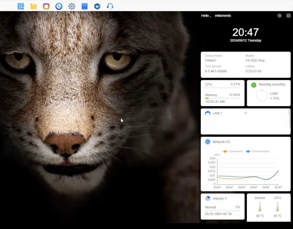
TOS has done away with a traditional dashboard-style layout with desktop icons and have instead added a taskbar along the top with little tooltips that come up to guide you around.
It feels fairly intuitive to use. It’s even got a sidebar to monitor system stats, which can be modified by dragging and dropping modules, and it includes a notification bar.
I really like their drive management and backup options. You have a lot of options for local and cloud backup. You can also set up an email address to automatically send notifications to if errors with drives or processes are detected.
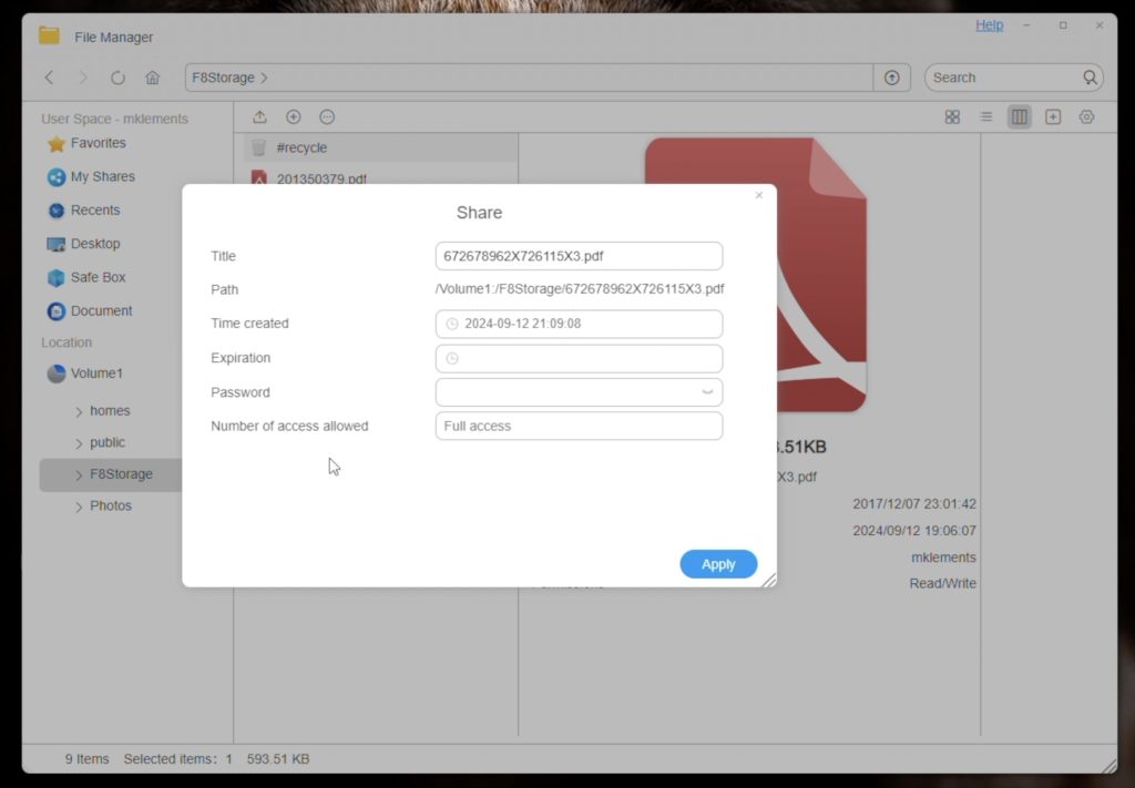
I also like their file management windows. Again, this interface has a Windows 11 look and feel, but that makes it intuitive. You’ve got right-click options for files and folders, you can create shares directly from this interface.
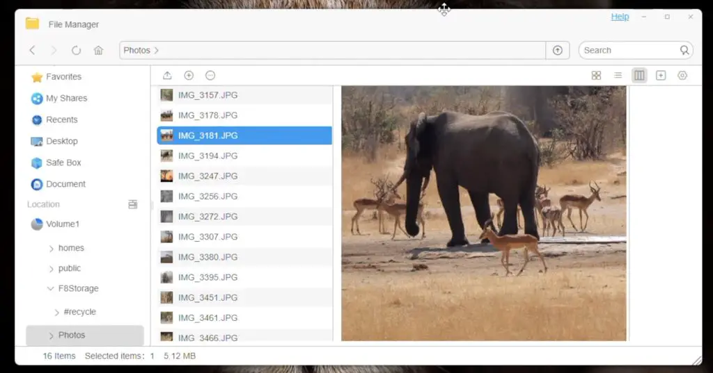
You can even preview some files like photos directly from the file management window.
You can quickly search for settings or features from the settings window, so you don’t have to waste time looking through menus.
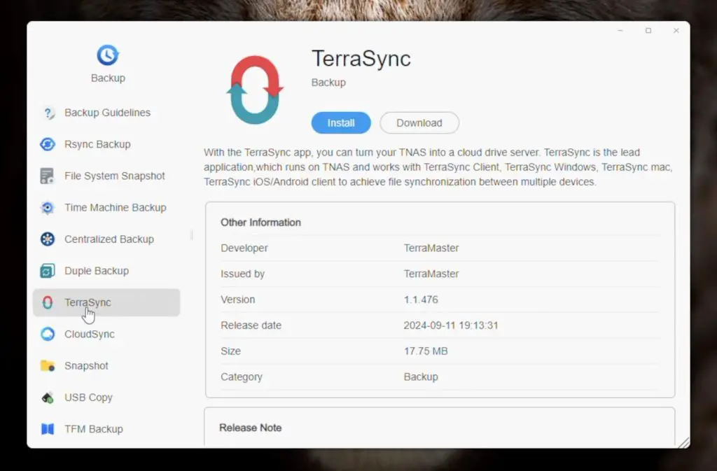
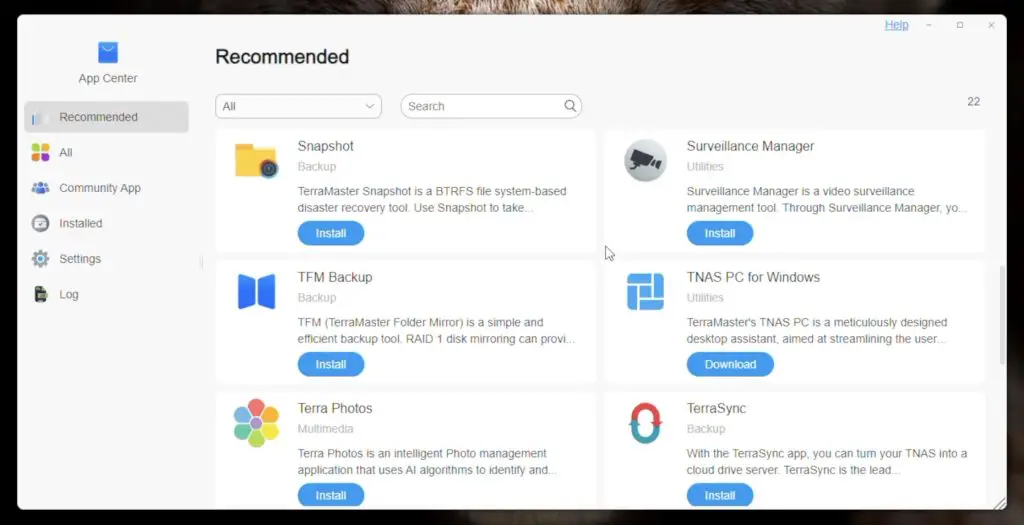
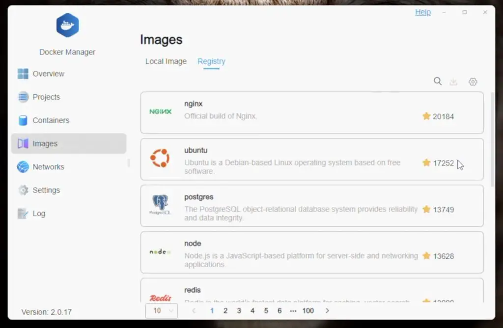
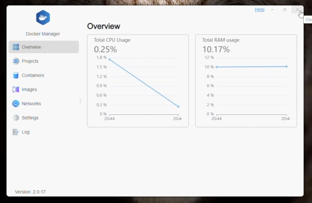
TerraMaster have also included a nice array of apps that you can install to add functionality to your NAS.
If you can’t find what you need with these apps, you can also quite easily install docker to deploy your own containerised apps. The CPU in this NAS has a fair amount of headroom to run these, so the F8 SSD Plus will work well as a small home lab.
That’s a brief overview of TOS 6. If you don’t like their software you can also install your own operating system like TrueNAS or Unraid on the NAS if you’d prefer.
Testing The F8 SSD Plus’ File Transfer Speed
Next, let’s do some transfer speed tests. I first used AJA System Test to automatically test the transfer speeds and then I did a real-world test on Windows 11.
AJA System Test
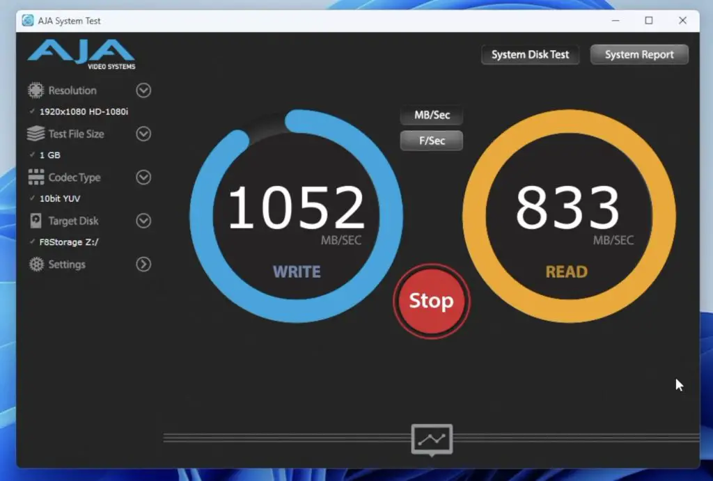
Transferring a small 256MB file, I got fairly consistent writes a little over 1000MB/s and reads around 850MB/s.
Going up to a 1GB file, we get very similar results – writes a little over 1000MB/s and reads around 850MB/s.
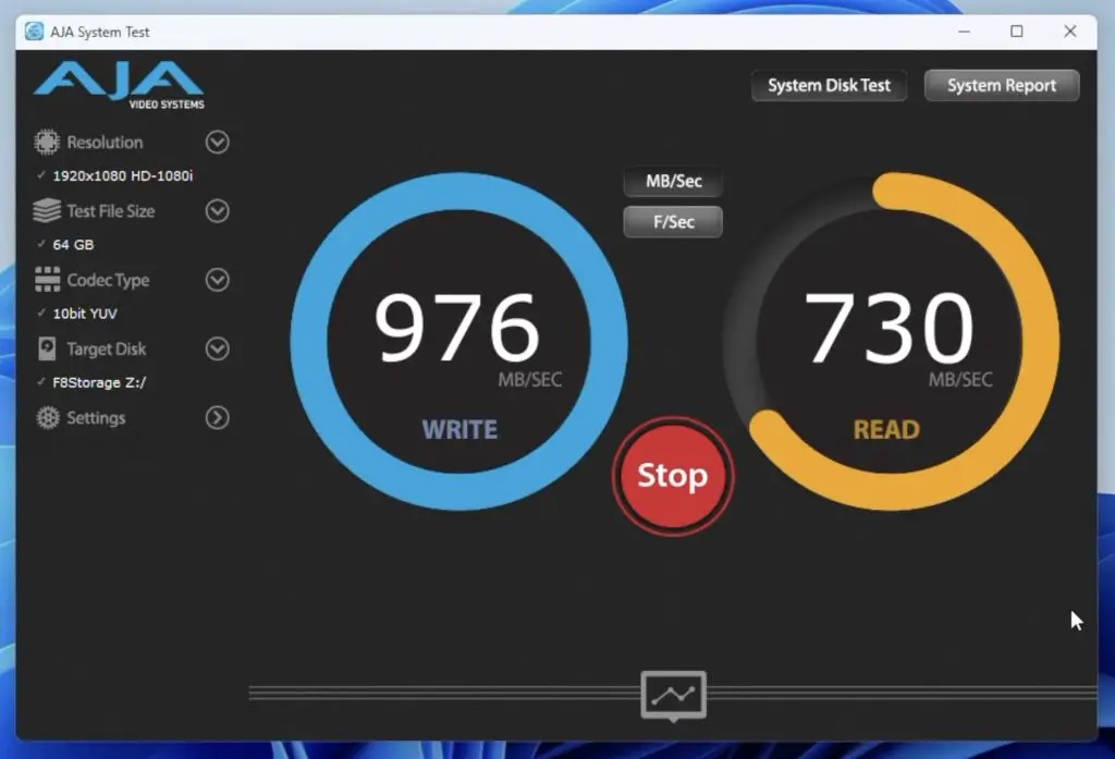
Transferring a 64GB file started off much slower than the previous two tests. Writing started off 500MB/s but then ramped up during the first half of the transfer and eventually settled at a little under 1000MB/s for the remainder of the write. Reading the 64GB file was stable but was again slower than with the smaller files. Reading remained at a bit under 750MB/s. So both reads and writes were about 100MB/s slower with the large 64GB file.
Windows 11 File Transfer Test
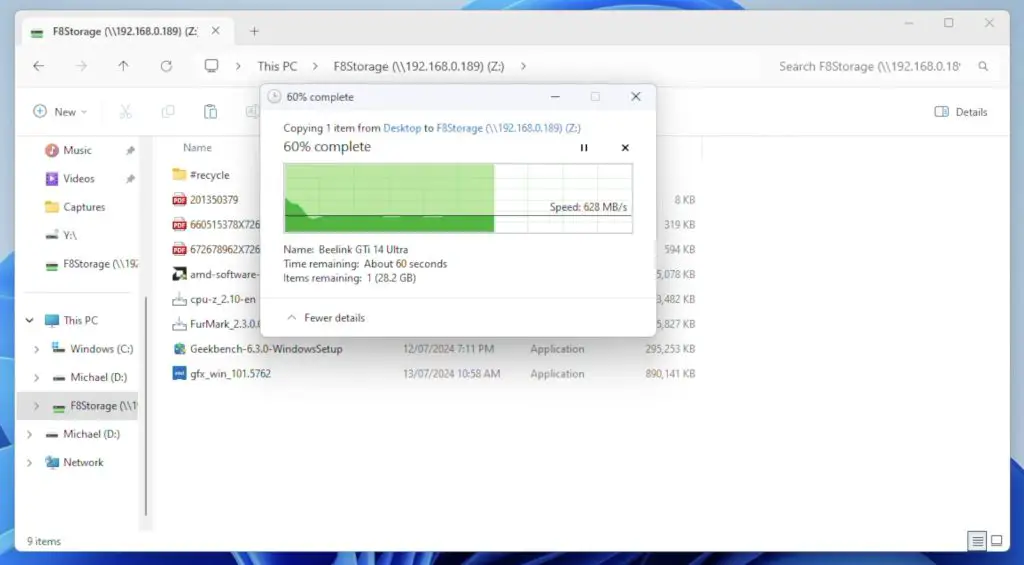
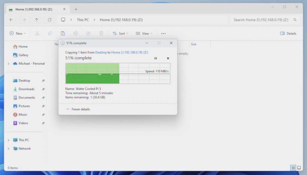
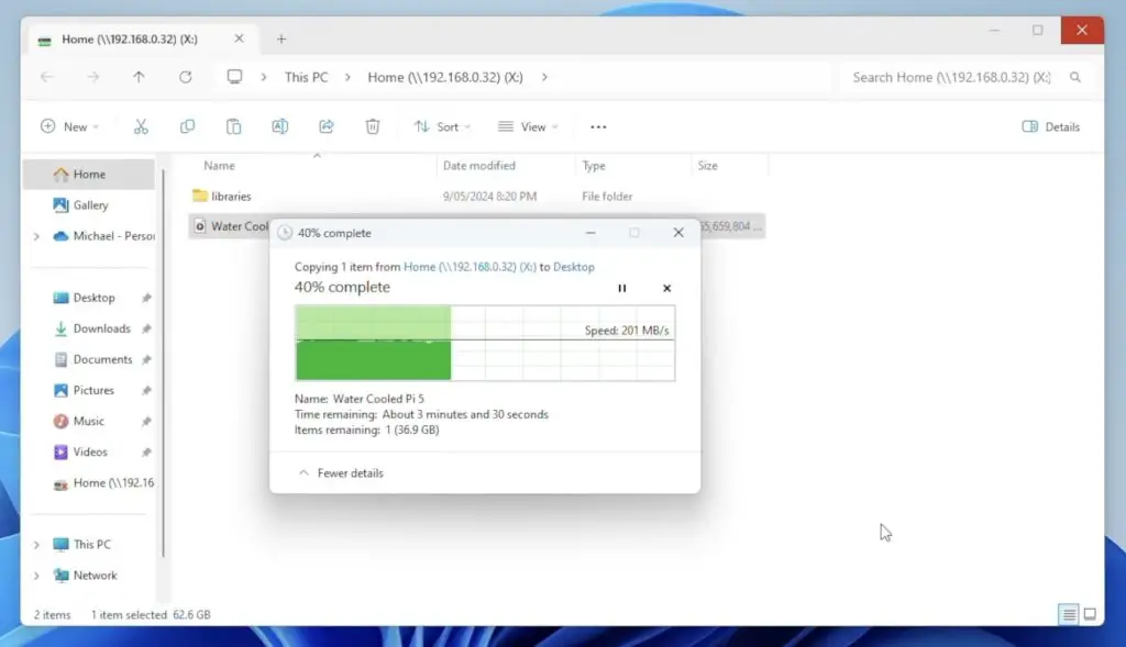
Running a real-world transfer test in Window 11, copying a large 70GB video file to the NAS, writes started off saturating the 10Gb Ethernet connection at 1.1GB/s. This dropped off quite quickly though and eventually settled at a little under 650MB/s for the remainder of the transfer.
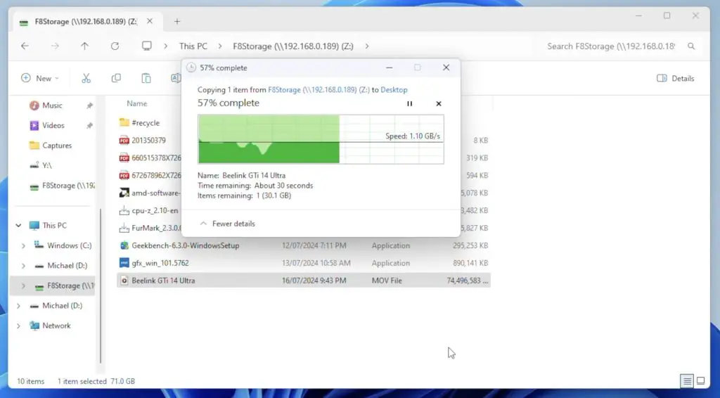
Reading the same 70GB video file from the NAS was much faster. Reading stayed at 1.1GB/s for most of the transfer, with just a couple of short dips.
So, overall my testing proved pretty good performance for file transfers. Like with my other NAS reviews, this is straight out of the box with the default setup. I haven’t done any tweaking or optimising of settings.
Fan Noise On The F8 SSD Plus
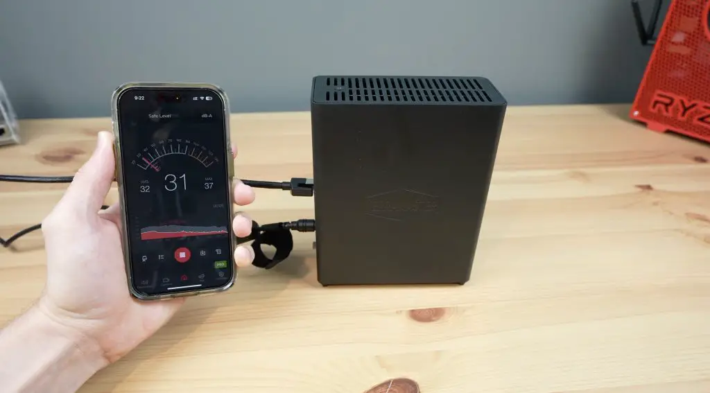
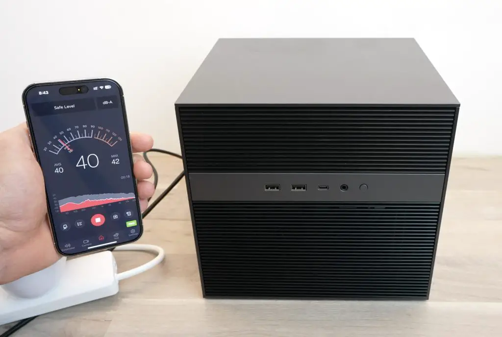
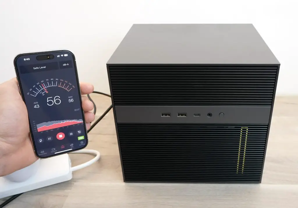
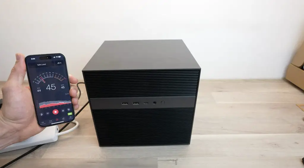
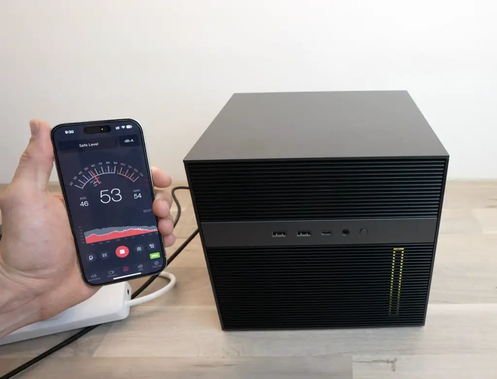
The F8 SSD Plus is very quiet as it doesn’t emit any physical drive noise. Fan noise is also minimal, you can hardly hear the fans running when at idle. The ambient sound level in my testing room is about 32 decibels, so the fans running at low speed barely register.
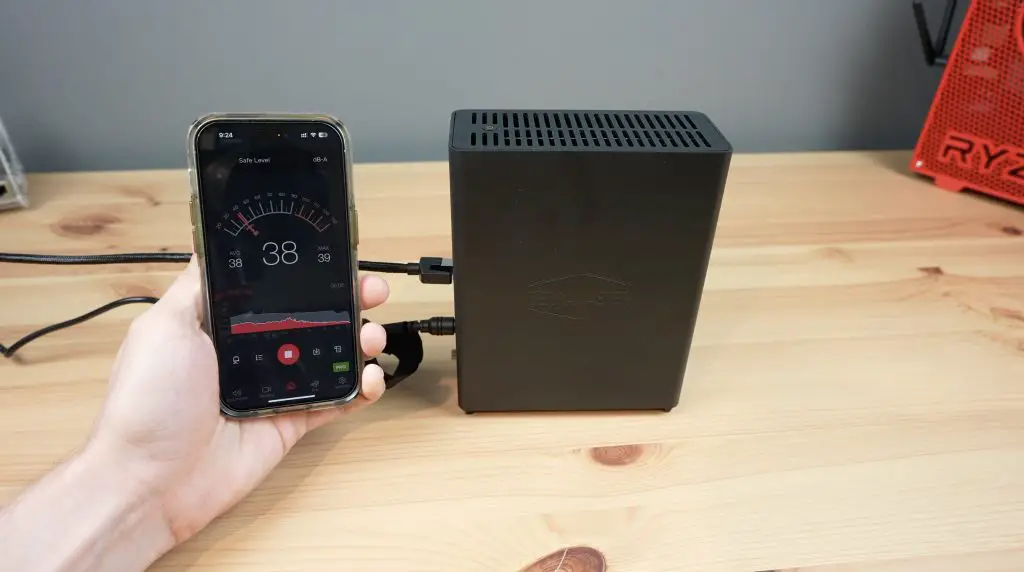
When writing to the drives or doing CPU-intensive tasks, you can hear the fans spin up but they’re not much louder. The sound level goes up to about 39-40 decibels.
So this NAS is ideal for a home or small office where you’d have the NAS in the same room that you’re working in.
F8 SSD Plus Power Consumption
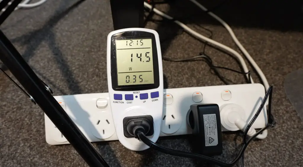
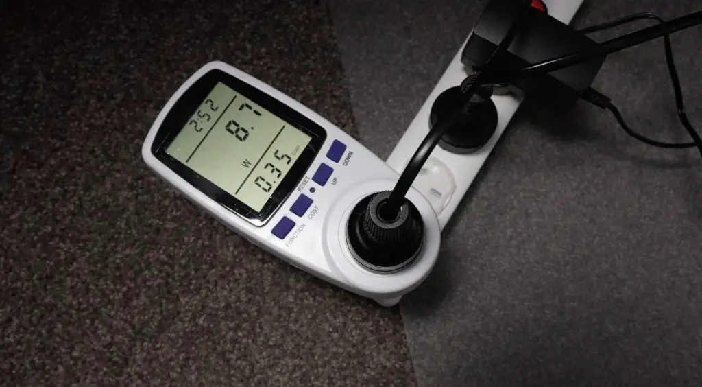
Keep in mind that power consumption will obviously vary with the type and quantity of drives installed, so you may get slightly different results. With my 4-drive setup and with the CPU under no load, we get a power consumption of 14W.
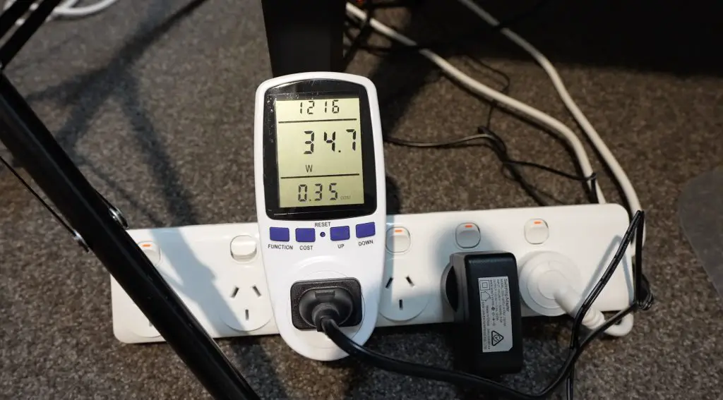
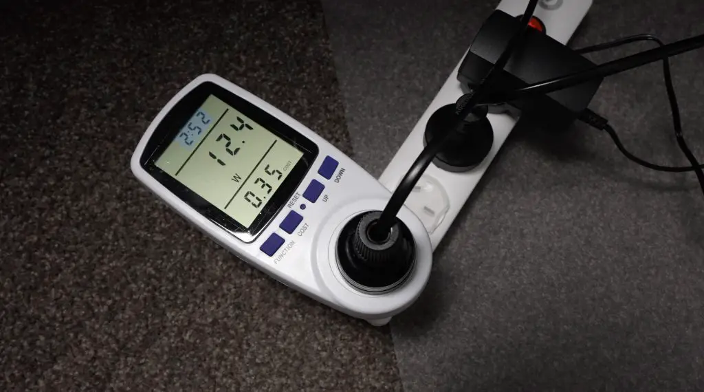
This goes up to 35W when writing to all four drives and saturating the network connection.
TOS 6 does have an option to put the drives to sleep if there is no activity for a period of time and this should further decrease the idle power consumption. In their documentation, they say that this will bring power consumption down to 9W. This seems reasonable from my test results.
Limitations of the F8 SSD Plus
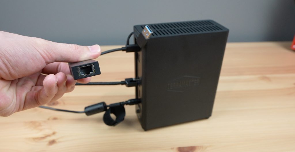
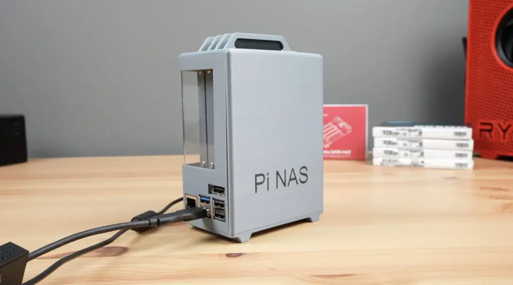
Most NAS products in this sort of price point would come with a secondary network connection, so it would have been nice to see a 2.5Gb network port alongside the 10Gb port as a secondary port or failover. You could add an external network adaptor to one of the available USB ports like I did with my Pi NAS, so this is not a major issue.
Each M.2 port also only supports PCIe gen 3 x 1 drive speeds. This sounds slow, but the limitation has to do with the available PCIe lanes on the processor. The i3 N305 processor has only got 9 PCIe lanes available. TerraMaster have distributed these over the 8 drives and the 10G Ethernet port, providing one lane each. I think they’ve made a fair choice here as the drives would individually saturate the 10G port in any case. So you’re not actually losing drive speed. This is worth keeping in mind when choosing drives though as you can save some money by buying older and/or slower drives that work well with the available interface.
The only other limitations I could find are that the F8 SSD Plus doesn’t have ECC memory and is missing native support for ZFS. Neither of these are particularly big concerns, they’re just worth noting.
Final Thoughts On The F8 SSD Plus
Overall I think this is a great product and I haven’t found any significant issues with it. There are a few features that would have been nice to have had included since it is quite pricey, but once you add an NVMe adaptor and 10Gb Ethernet adaptor to a mini PC of a similar size and performance, you’ll probably be around this price point too.
Let me know in the comments section below if you think I should have a go at building my own single board computer based NAS with similar functionality to see how it compares. Also, let me know what you think of the F8 SSD Plus.
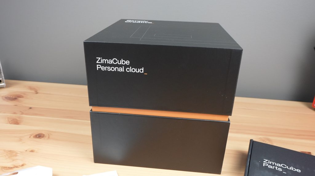
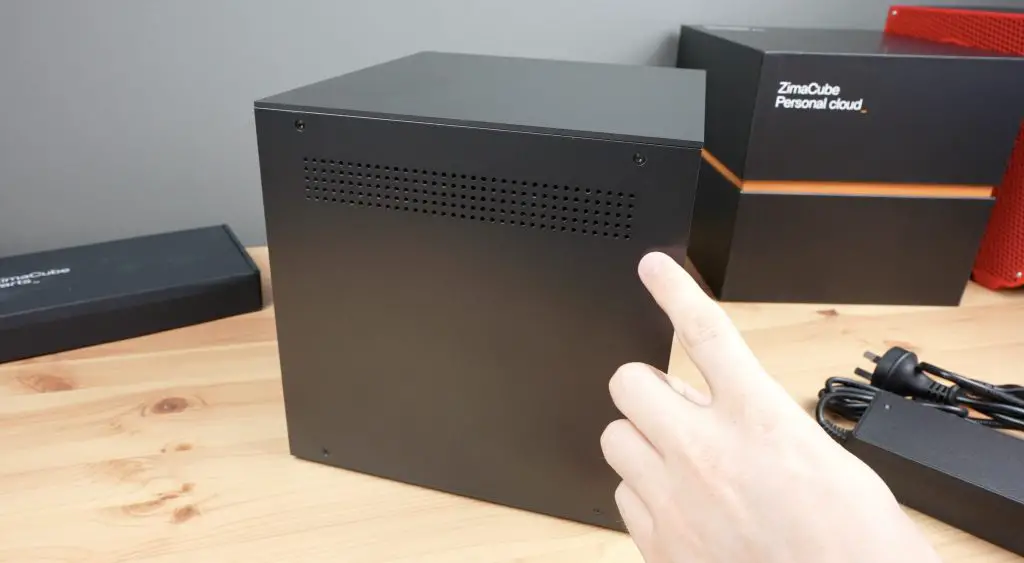
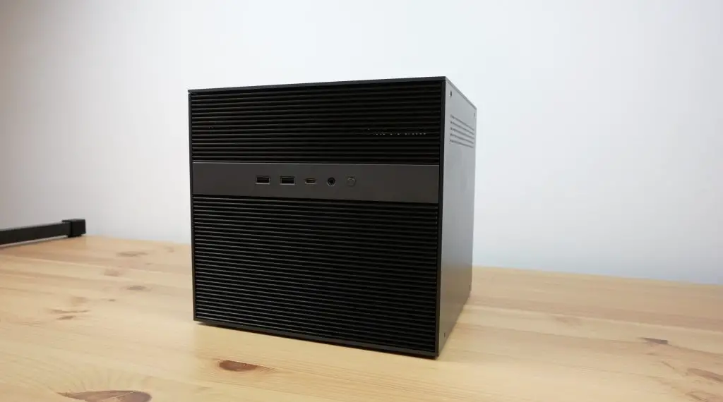
Today we’re going to be taking a look at the ZimaCube Pro. This is a new device from IceWhale, the company that have already brought us the Zimaboard and Zimablade that I’ve reviewed previously.
The Zimacube Pro is the second device from their Kickstarter crowdfunding campaign that was successfully funded in December last year. It is marketed as being a personal cloud server with easy-to-use software and has more powerful hardware than the standard Zimacube from the same campaign.
Here’s my video review of the ZimaCube Pro, read on for the written review;
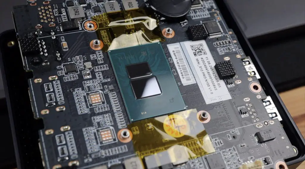
The ZimaCube Pro has a 12th generation Intel i5 processor instead of the Intel N100 processor in the standard cube. This allows for faster RAM, better PCIe expansion, faster M.2 ports and significantly better connectivity. It comes a price though, the Pro version currently retails for $1099.00, which is a significant step up of $450 from the standard version that retails for $649.00.
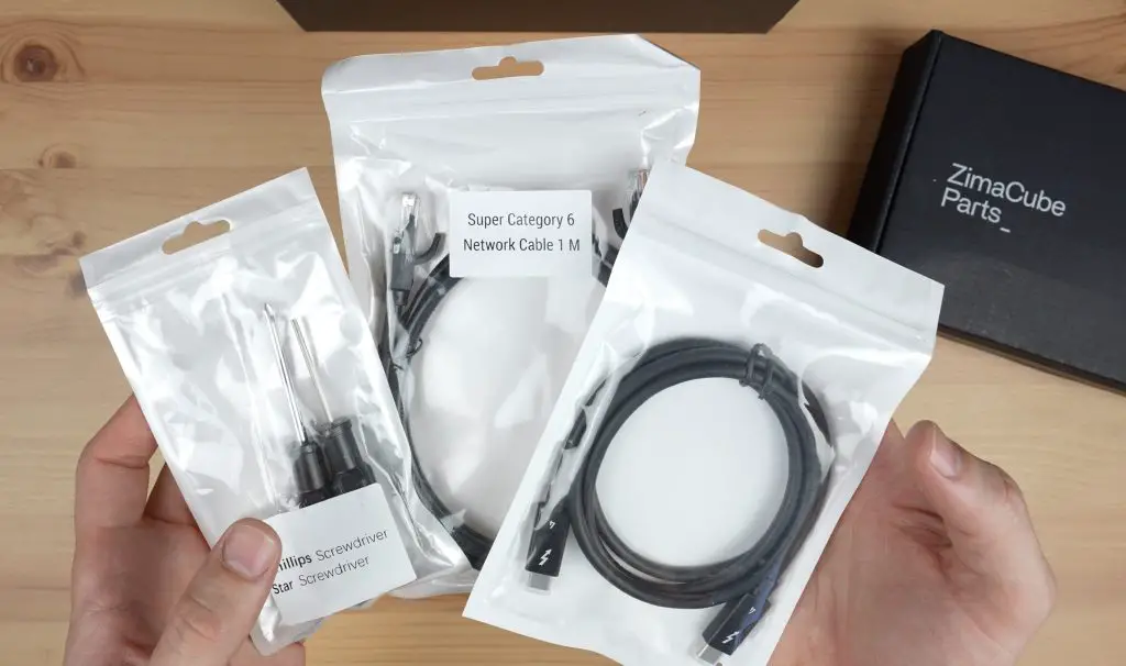
Included in the box are some basic tools, a Cat6a network cable, a Thunderbolt 4 cable, a power adaptor and some screws for mounting the drives into the drive bays.
Ports and Interfaces on the ZimaCube Pro
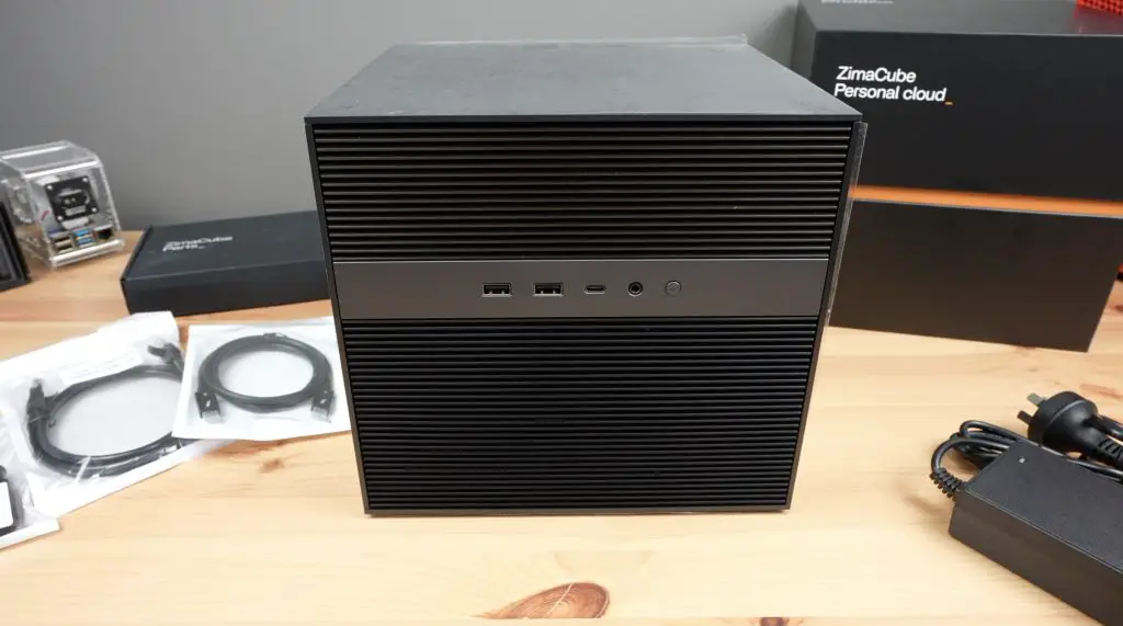
Taking a look around the Zimacube Pro. On the front, we’ve got two USB 3.0 ports, a USB type C port, a 3.5mm audio jack and the power button.
Below that, under the ventilation grill, it’s got six SATA drive bays which can take 2.5” or 3.5” drives and a 7th tray that has four M.2 ports for NVMe drives.
The 7th tray also has customisable and programmable RGB lighting with an onboard controller that you can load custom firmware onto.
The ZimaCube Pro also has two internal M.2 ports – one of these being for the OS storage drive. So that’s a total of 6 SATA ports and 6 M.2 ports, which allow up to 164TB of connected storage.
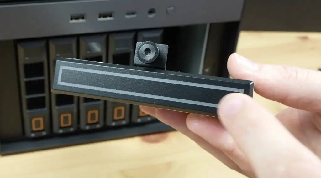
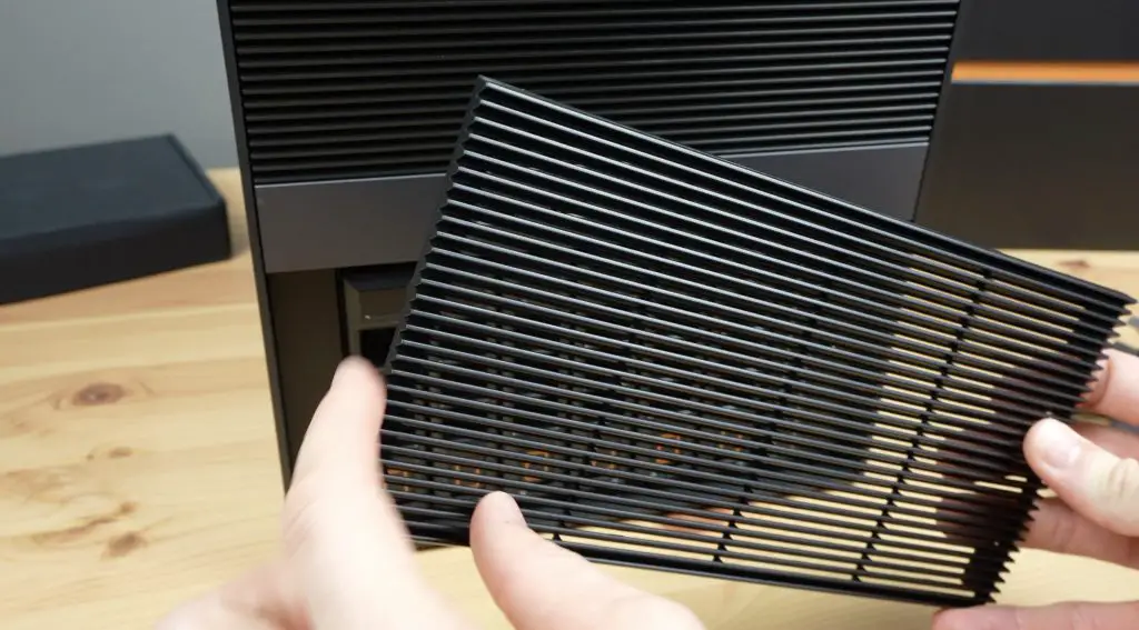
This ventilation screen that covers the bays looks great when it’s installed but could really do with a small tab or recess on the edges to make it easier to remove.
The sides each have ventilation holes at the top and four screws holding the top and bottom covers in place.
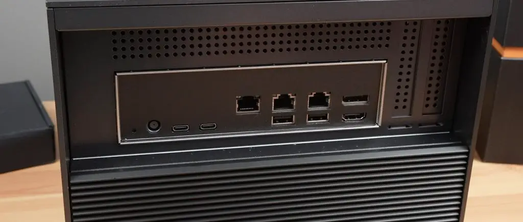
On the back of the ZimaCube Pro, we’ve got a reset button, the power input, two Thunderbolt 4 ports, a 10Gb Ethernet port, two 2.5Gb Ethernet ports, two more USB 3.0 ports, a DisplayPort 1.4 and an HDMI port.
The Thunderbolt 4 ports allow the Zimacube to be used as a DAS (Direct Attached Storage) device. This is a feature that is not commonly found on consumer-level products, so I’m interested to see how well this works. They claim that you can get up to 2GB/s transfer speeds through this port, so we’ll definitely be testing that out!
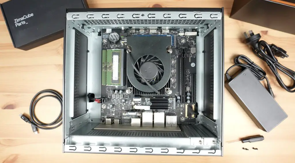
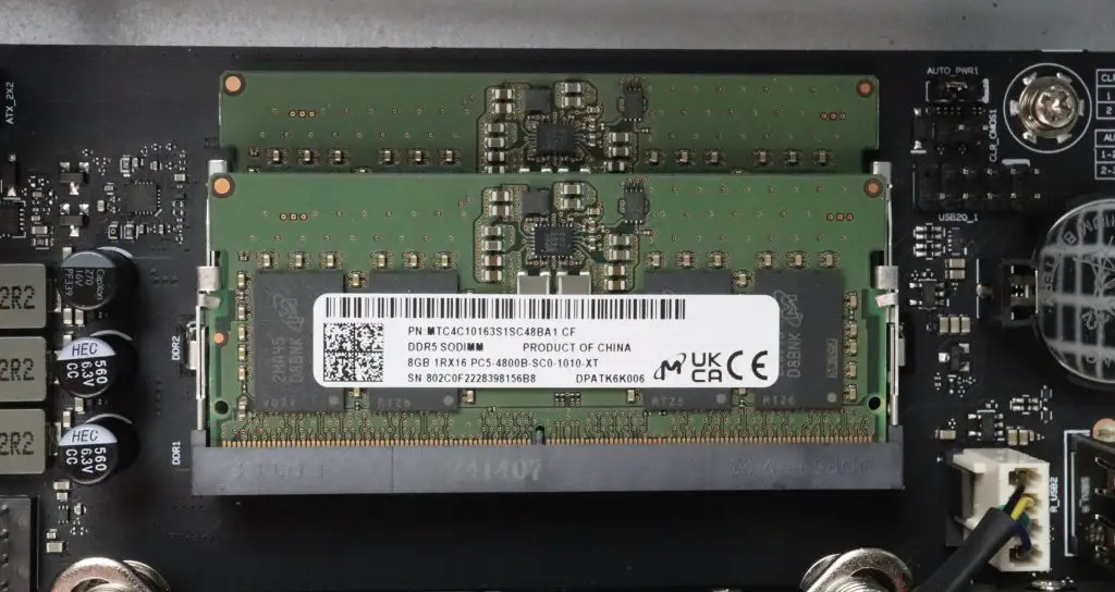
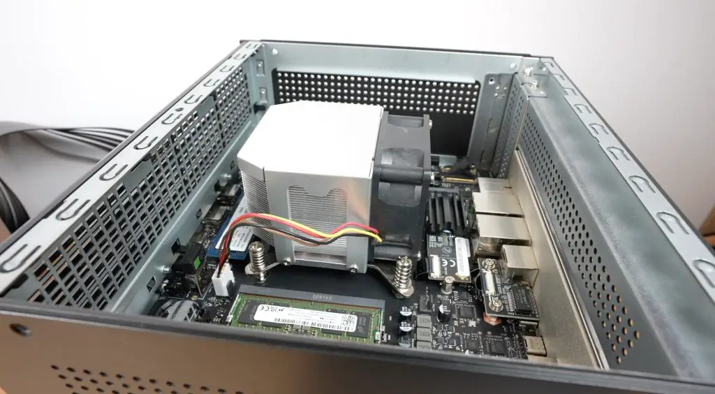
Internally, as mentioned earlier, powering the Zimacube Pro is a 12th gen Intel Core i5 processor, it is the 1235U version with 10 cores running up to 4.4GHz. This particular one has 16GB of DDR5 RAM, but this can be expanded up to 64GB.
We’ve got dual PCIe slots, one being PCIe 4.0 x 4 and the other PCIe 3.0 x 2. These allow you to add expansion cards like a GPU, an AI acceleration card or a transcoding card to improve the Zimacube’s performance for your particular workflow.
Our 256GB M.2 NVMe OS drive is partially hidden by the cooler.
The M.2 port near the back is populated with the 10GB Ethernet adaptor and a short tail to a daughterboard with the physical port on it.
One of the main complaints early users have had is with the ZimaCube Pro’s cooling solution. It is claimed to be quite loud and not very effective. IceWhale have responded to concerns by providing a free issue improved cooling solution for backers – which is supposedly quite easy to swap out. We’ll test this against the currently installed cooler to compare the results.
ZimaOS – The Intended Operating System
As with other IceWhale products, it is intended to be used with their own operating system. In this case, it comes preloaded with ZimaOS. This is very similar to CasaOS which is loaded onto the ZimaBoard and ZimaBlade, with a few features tailored to the ZimaCube like RAID support and remote access functionality.
You’re not locked into using their software though. You can fairly easily install other operating systems like OpenWRT, pfSense, TrueNAS or Unraid.
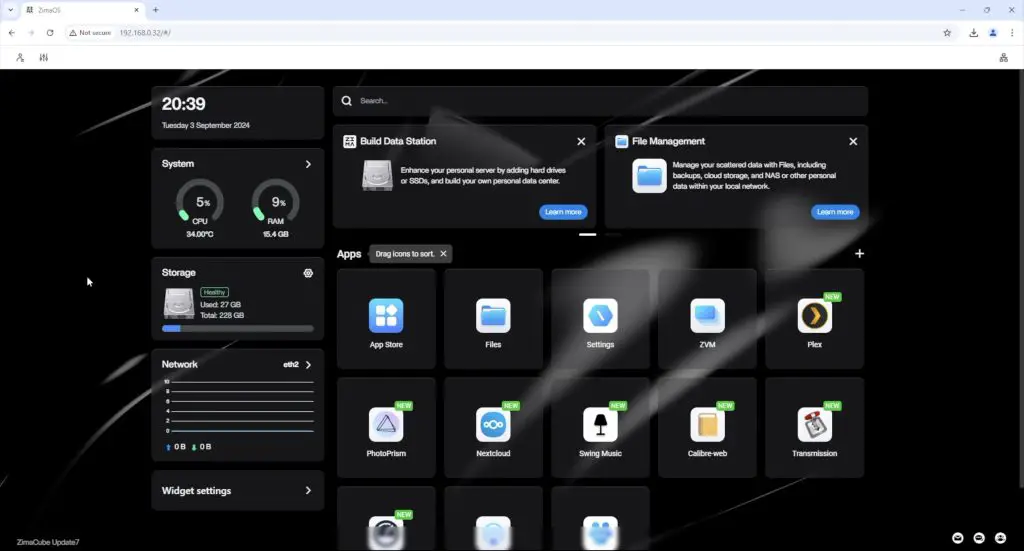
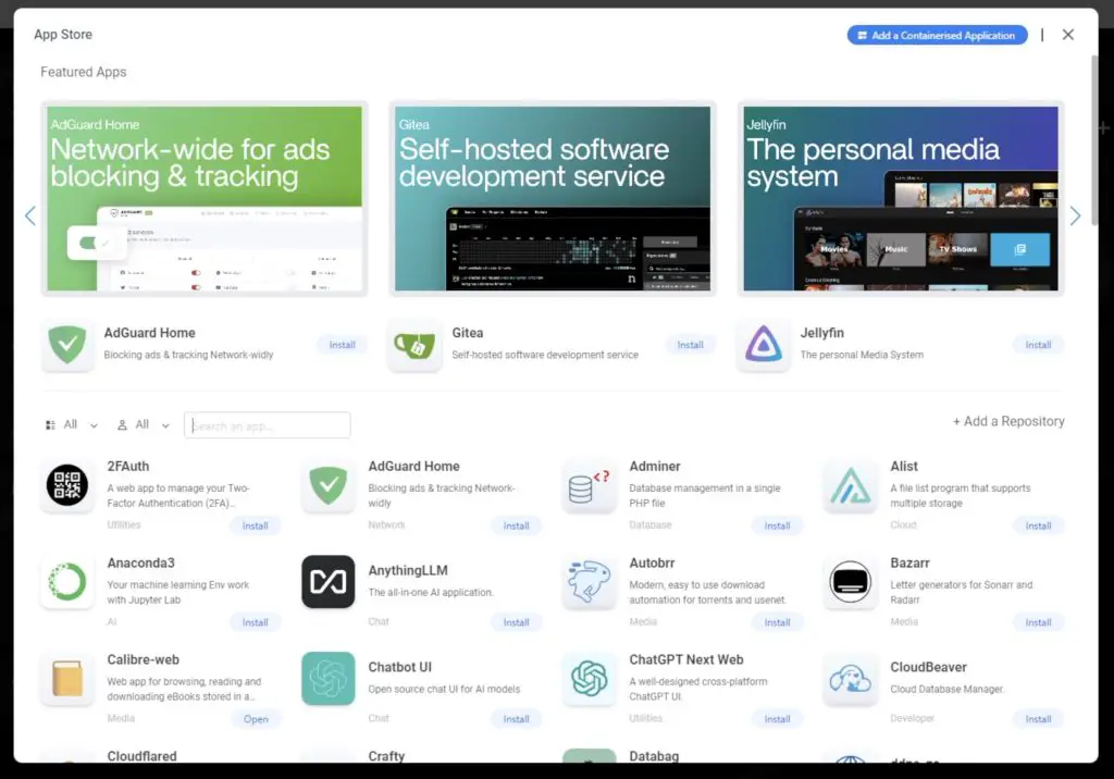
ZimaOS is effectively a skin for docker with a bit of additional functionality and a good support community. It’s got a range of preconfigured apps that are very easy to set up and you can configure your own apps through the web dashboard or by loading your own .yaml files.
Testing The Cooling Solution
Let’s start by testing the old and new CPU cooling solutions. I haven’t done anything to the stock cooler, I’ve left it as it arrived. Some users reported having their CPU cooler installed with the plastic protector left in place on the contact surface. To test the thermals, I’m going to first try a 50% load on the CPU and see what the does to the CPU temperature and then I’ll try a 100% load.
Old Cooling Solution
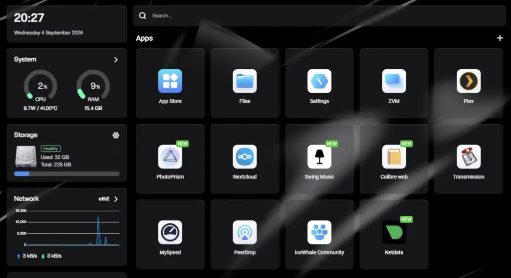
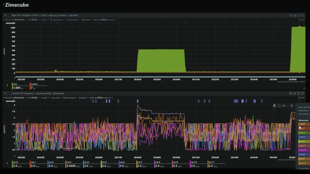
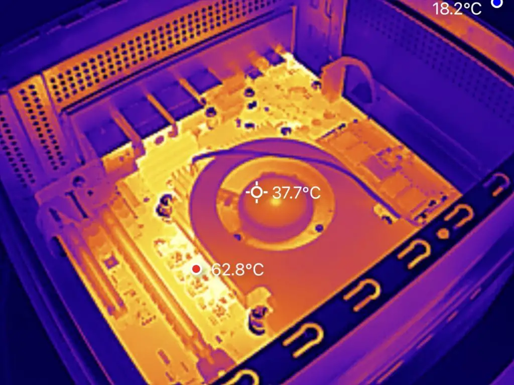
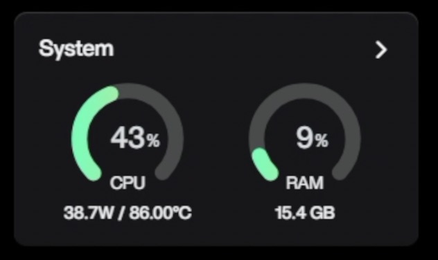
The temperature is already sitting quite high at idle. We’re at 2% CPU utilisation and are already running at over 40°C in a 20°C room.
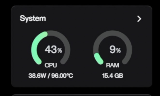
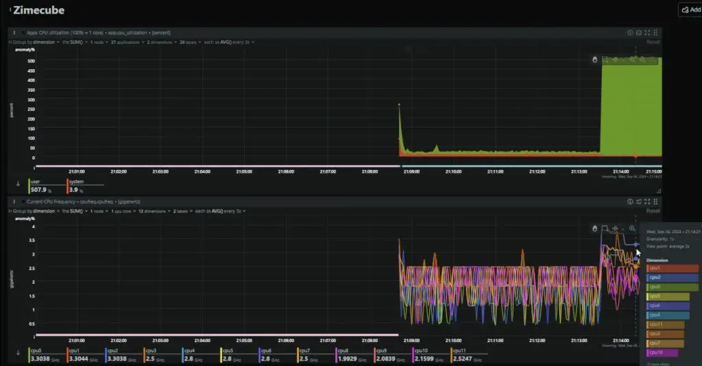
At 50% load, the temperature spikes to over 90°C in about 2 seconds, which is really quite poor. The CPU starts thermal throttling almost instantly, dropping the clock frequency down to 3.5GHz and then further to 3.3GHz about 45 seconds later. This brings the temperature down a bit but obviously comes at the expense of performance.
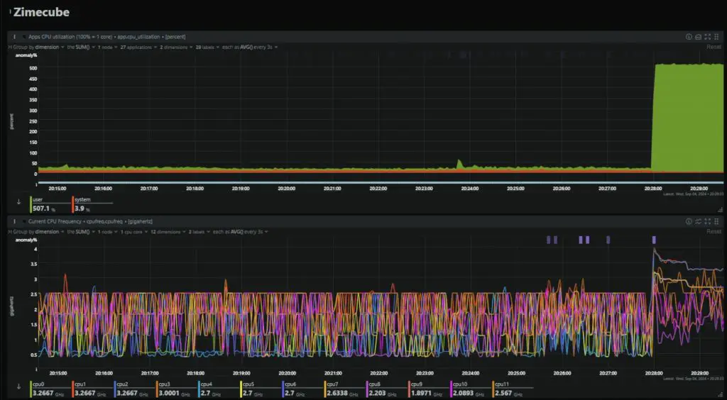
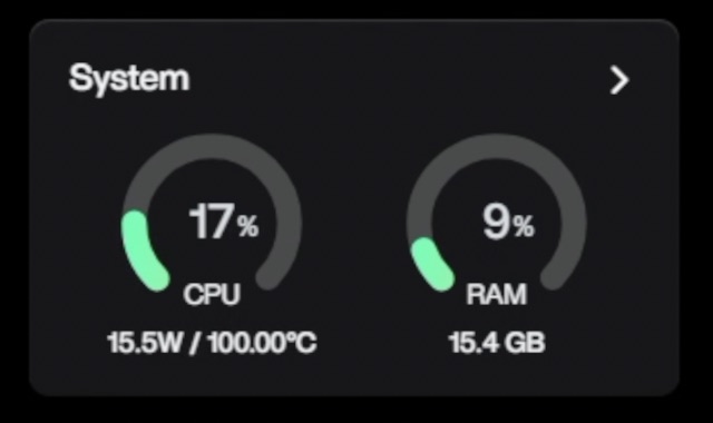
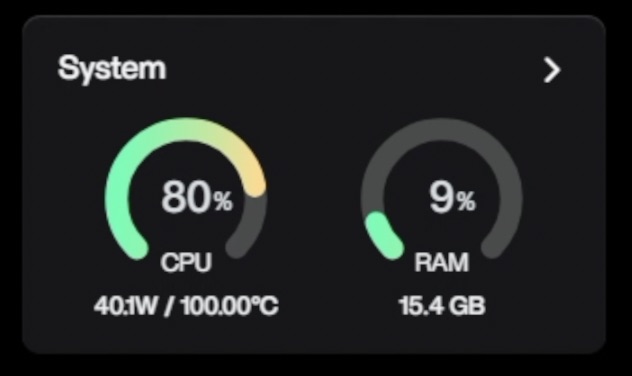
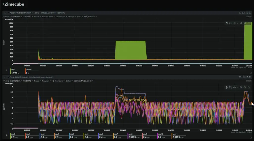
At 100% load, it’s practically useless for sustained use. The CPU temperature spikes to 100°C before the utilisation gauge can even increase and again is significantly thermally throttling, this time down to just 2.4GHz.
So this cooler is really undersized or just doesn’t work effectively – confirming other users concerns.
I have to also mention that the fans for the drive bay of the Zimacube are quite loud. I haven’t installed any drives into the bays, and I’m in an air-conditioned room, and the drive bay fans already spin up occasionally. So their curves must be set very low. That’s not necessarily a bad thing and you can adjust them in the BIOS. It’s just not great if you’re going to have the ZimaCube Pro near where you’re working.
The CPU cooler is audible but isn’t that loud when idle. When it spins up under any sort of load then it is quite load.
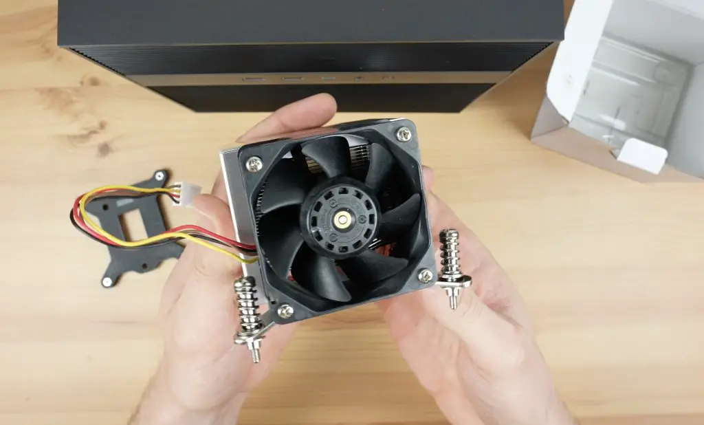
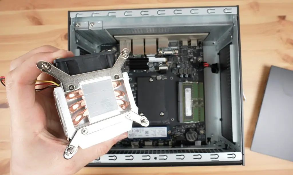
New Cooling Solution
Now let’s get the new cooler fitted. The cooler comes with a bracket for the underside of the motherboard but I believe it uses the same pattern and screws so we shouldn’t need to use this.
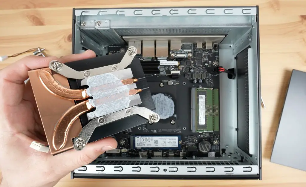
The old cooler is quite easy to remove. You just need to remove the four screws holding it in place and unplug the fan.
The new cooler has a preapplied phase change thermal pad on it so we don’t need to reapply the thermal paste. I cleaned the old thermal past off of the heat spreader to give it the best chance of success.
They say that it should be installed with the fan at the back of the Zimacube, directed towards the front, which I’ve done.
Now let’s boot it up and see if it performs any better.
At idle after booting up, we’re now running about 8-9°C cooler at 33-34°C.
Again starting with a 50% load, it now takes about 10 seconds to run over 90°C. This is a significant improvement over the previous cooler, but it still starts thermal throttling under sustained load.
With a 100% load, we again hit 100°C and started thermal throttling almost instantly. It sustains a slightly higher CPU frequency for a short while longer, but not that significantly.
In terms of fan noise. The new cooler runs a little louder at idle but is a little quieter under full load. So not a significant difference.
The new cooling solution makes some improvements to the thermals but if you plan on doing CPU intensive tasks for long periods of time then you’ll probably still want to upgrade the cooling solution.
Given how quickly the temperature spikes under full load, I think some of the limitation might actually be with the heat spreader as it’s a painted surface. There may also be issues with the way the heat spreader is interfaced to the CPU.
Testing NAS Transfer Speeds
Now let’s get some drives installed into the ZimaCube Pro and do some transfer speed tests on it.
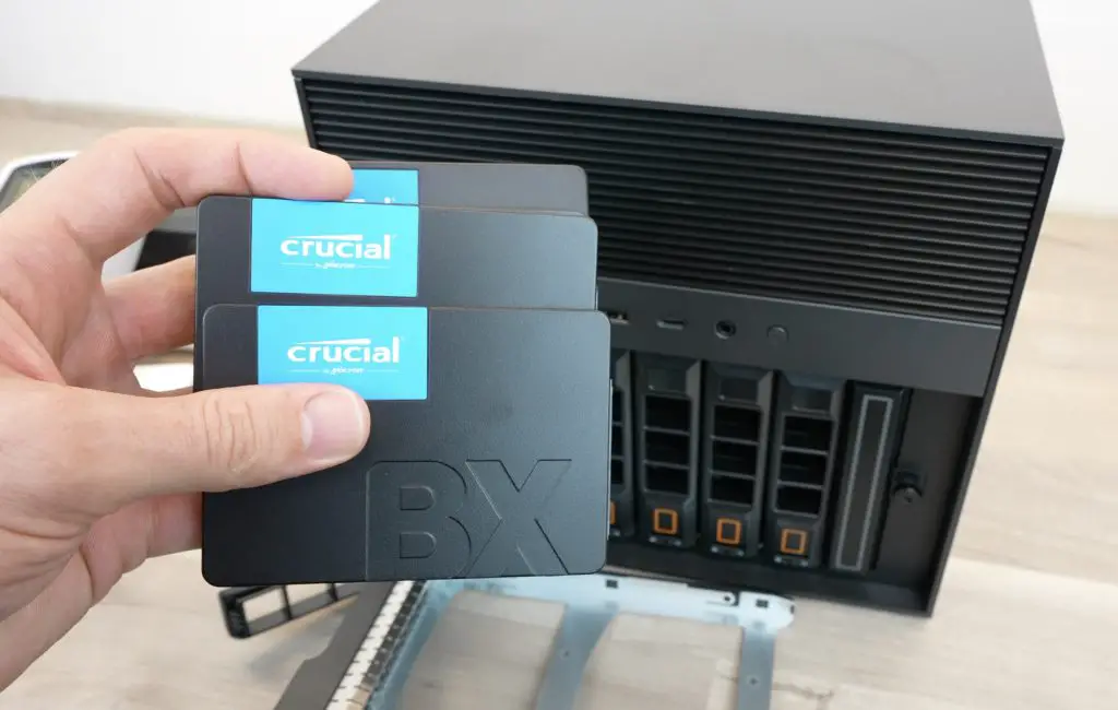
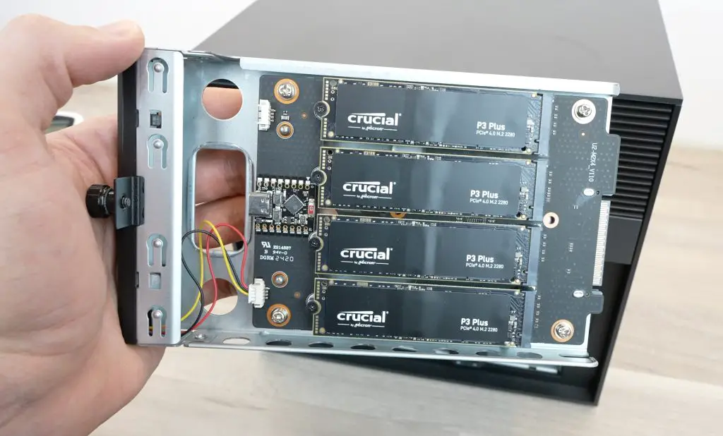
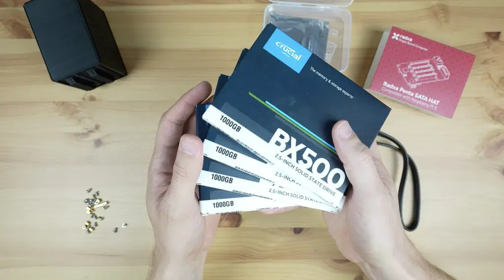
I’m going to install four 2.5” Crucial BX500 SSDs in the main bays and four Crucial P3 Plus NVMe drives in the M.2 bay.
These aren’t ideal for a NAS but they’re what I have available for testing. If you’re going to be using drives in a NAS long term then make sure that you use NAS grade drives and preferably ones with DRAM cache.
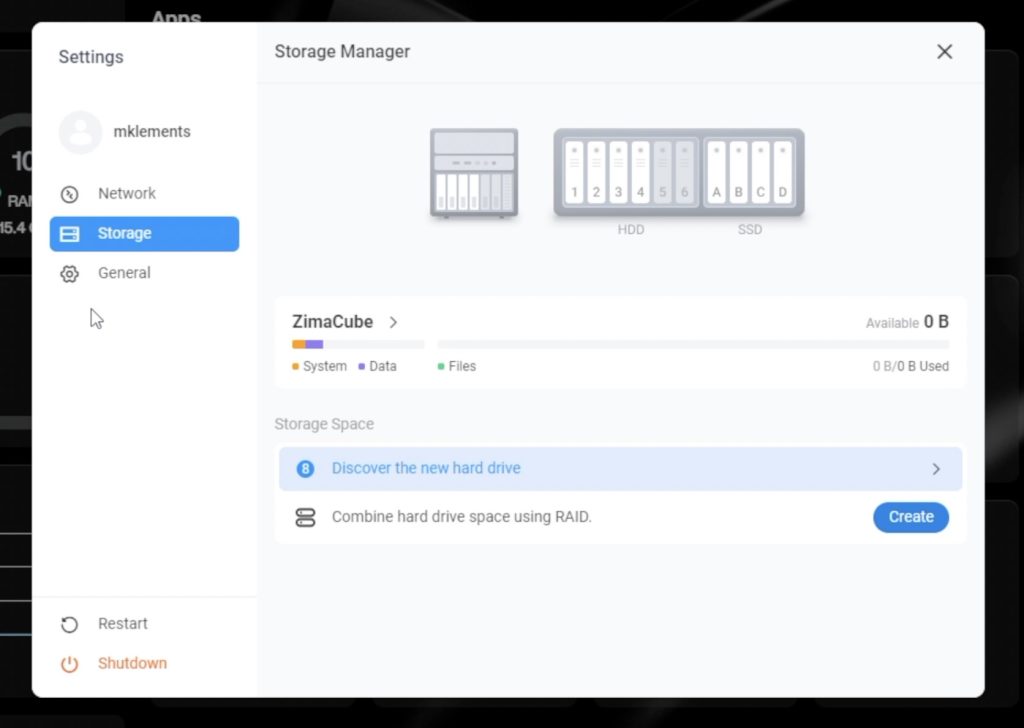
Our drives now show up in our dashboard and we can set them up as individual drives or in a RAID configuration.
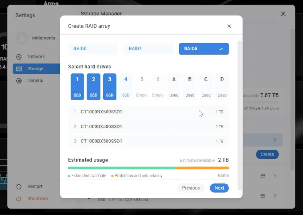
I’m going to go with RAID 5 and I’ll set up the NVMe drives in one pool and the SATA drives in a second pool.
I had to reformat the SATA drives as I used them for my Pi NAS and they were already in a RAID configuration that the ZimaCube Pro didn’t like.
NVMe Storage Volume Test
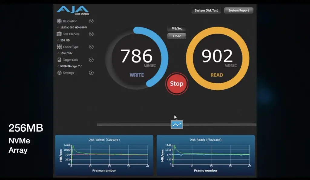
Using AJA System Test, and starting with a small 256MB file on the NVMe storage volume. We get writes of around 700MB/s and reads around 900MB/s. So writes are a little under saturating the 10Gb Ethernet connection but reads are very close. I haven’t done any optimisation or tweaked any settings on the NAS so this is straight out of the box with very little setup. With a 1GB test file we get similar results.
Going up to a large 64Gb test file, we get a similar write speeds but our read speed drop off quite a bit, down to 750MB/s.
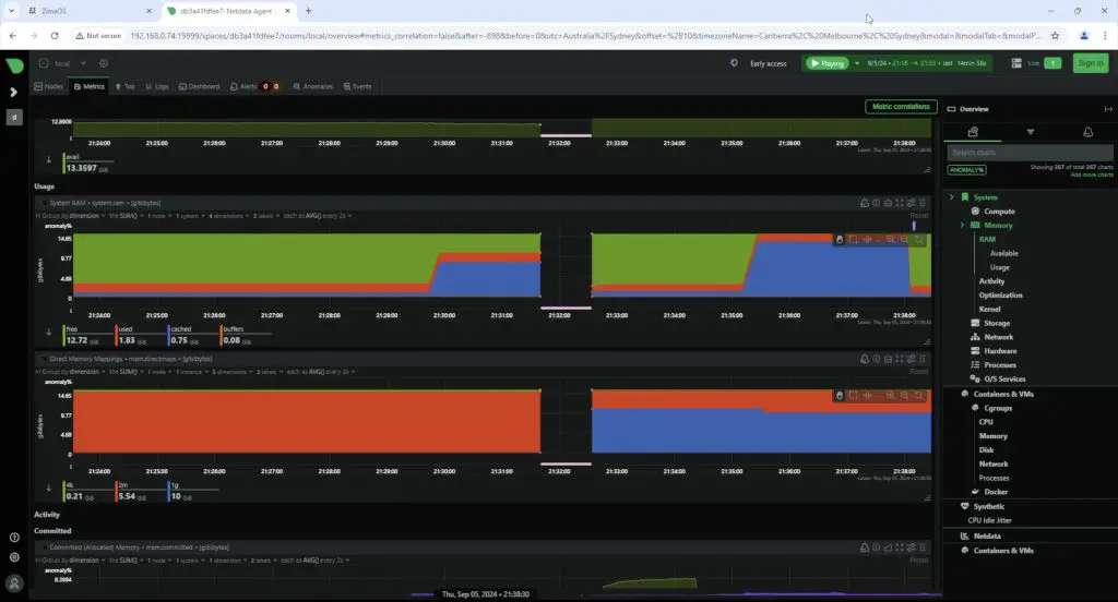
I’ll have to do some digging to figure out why, but it seems like it likely has to do with the ZimaCubes Pro’s available RAM. The ZimaCube Pro is probably not able to write to the NVMe drives fast enough to keep up with the network adaptor, so the RAM fills up and then the drive’s write speed becomes the bottleneck.
NVME Volume Results Summary:
256MB: 700MB/s Writes, 900MB/s Reads
1GB: 700MB/s Writes, 900MB/s Reads
64GB: 700MB/s Writes, 750MB/s Reads
SATA Storage Volume Test
Switching over to the SATA storage volume.
For the 256MB and 1GB test files we get very similar results to the NVMe drives.
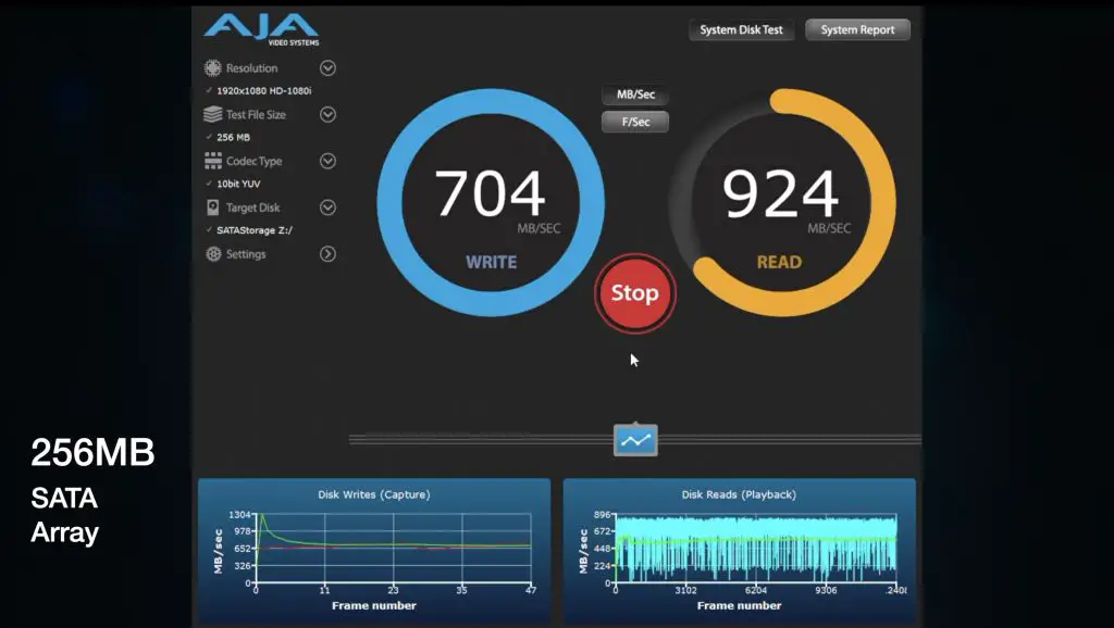
When we go up to the 64GB test file, writes start off well but then drop quite considerably. We get about a third of what we got with the NVMe volume. Again this seems to be related to RAM filling up because the drives can’t keep up with the write speed.
Reading the 64GB test file from the SATA volume we get similar results to the smaller files so there are no issues here.
SATA Volume Results Summary:
256MB: 700MB/s Writes, 900MB/s Reads
1GB: 700MB/s Writes, 900MB/s Reads
64GB: 250MB/s Writes, 750MB/s Reads
Real-world Window’s 11 File Transfer Test
Running some real world file transfer tests in Windows 11, we get good results.
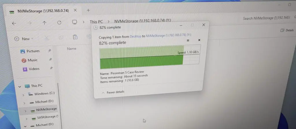
Copying a 60GB video file to the NVMe storage volume, we get a very stable sustained 1.1GB/s.
Copying the same file from the NVMe storage volume, we again get a fairly stable 1.1GB/s. There were two occasions where the transfer speed dipped significantly, but it picked up again fairly quickly.
Thunderbolt 4 Transfer Test
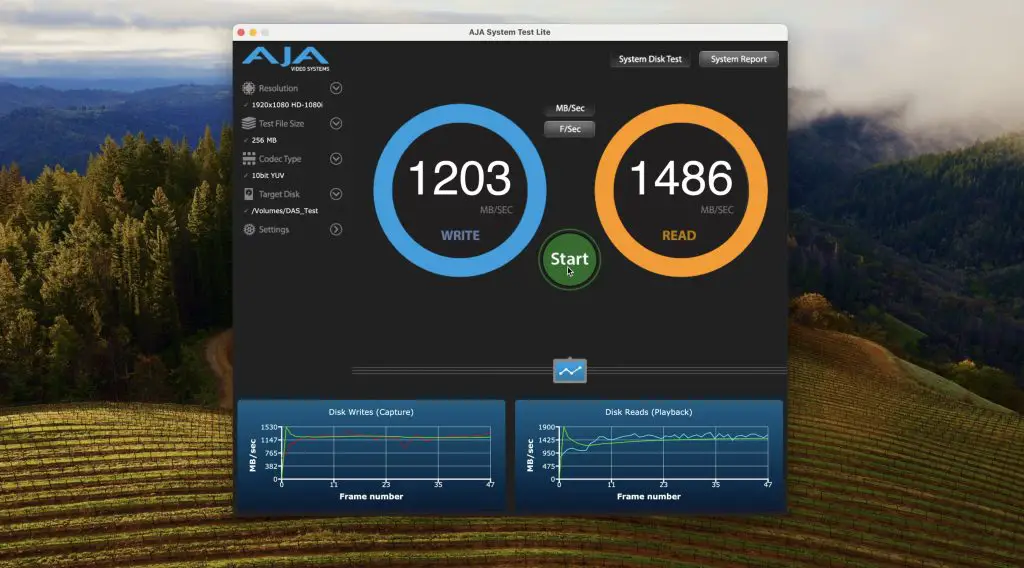
When directly connected to my Mac over Thunderbolt, I tried that same three file size transfer tests.
The 256MB test file averaged around 1200MB/s writes and 1500MB/s reads but results were quite erratic.
The 1GB test achieved very similar results to the 256MB test file.
The 64GB file started off writing quite slowly but ramped up to 1000MB/s write. It then achieved faster reads than the previous file sizes, getting up to 1700MB/s – fairly close to the claimed 2000MB/s.
Other ZimeCube Pro Features
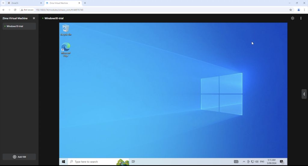
The ZimaCube Pro can also run virtual machines, so you can run multiple operating systems to support different applications and utilities.
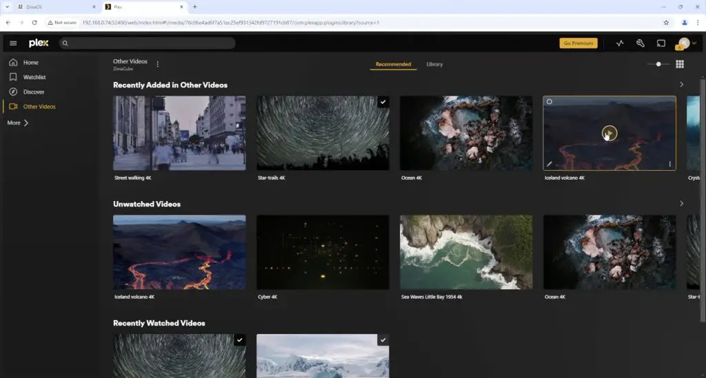
Plex running on the ZimaCube Pro handles 4K video playback really well. This obviously depends on how much transcoding is taking place, which is minimal for these sample videos, but they barely register on the CPU.
Some early users have already developed their own software for the RGB lighting in the 7th tray. It’s fully programmable through the onboard ESP32 module and each of the LEDs are individually addressable, which gives you a lot of options.
Power Consumption Tests
In terms of power consumption, the ZimaCube Pro is rated for up to 220W.
I did two tests as the total power draw will likely be quite dependent on the type and number of drives you’ve got running.
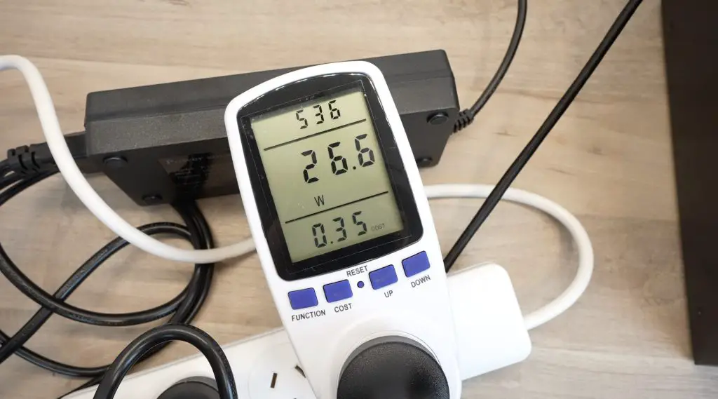
The first test was without any storage drives installed. With this setup I got a power draw of 27W when idle and it peaked to 81W when under full CPU load.
With four SSDs and four NVMe drives installed, I got an average idle power draw of 34W. This isn’t much of an increase from the 27W without drives, but SSDs are obviously a lot more power-efficient than physical disk drives.
With the 3.5” bays all populated with physical 3.5” drives, other users have measured around 50-60W with low CPU utilisation and 70-80W with high CPU utilisation. So still well under the rated consumption, but its going to cost a bit to have this running in your home 24/7. Here in Australia I’d be looking at about $8-10 a month to keep the ZimaCube Pro running with my current configuration.
Final Thoughts On The ZimaCube Pro
Overall I think the ZimaCube Pro is a great way to get started with running your own Personal Server in your home or small office. ZimaOS as it currently stands is a bit limited but they’re constantly adding new features to it and it’s simplicity makes it really easy to get a basic setup running, especially if you’re new to running a NAS or home server.
If you outgrow ZimaOS you can also easily transition to a more powerful NAS operating system like TrueNAS or Unraid.
There are a couple of things that I think they need to work on.
While the new CPU cooler is better than the original, there is still a lot of room for improvement. As I’ve said earlier, this may not even just be the cooler, it’s likely the CPUs heat spreader as well. The drive bay fans are also quite noisy and their curves are set a bit too low.
The removable front panel is great for aesthetics but could also do with some tabs to make it easier to remove. You have to sort of hook your fingernails in under the vents to pull it off. It’s not difficult to do but just feels clumsy.
Let me know what you think of the ZimaCube Pro in the comments section below and let me know if there is anything else you’d like to see me test or run on it.
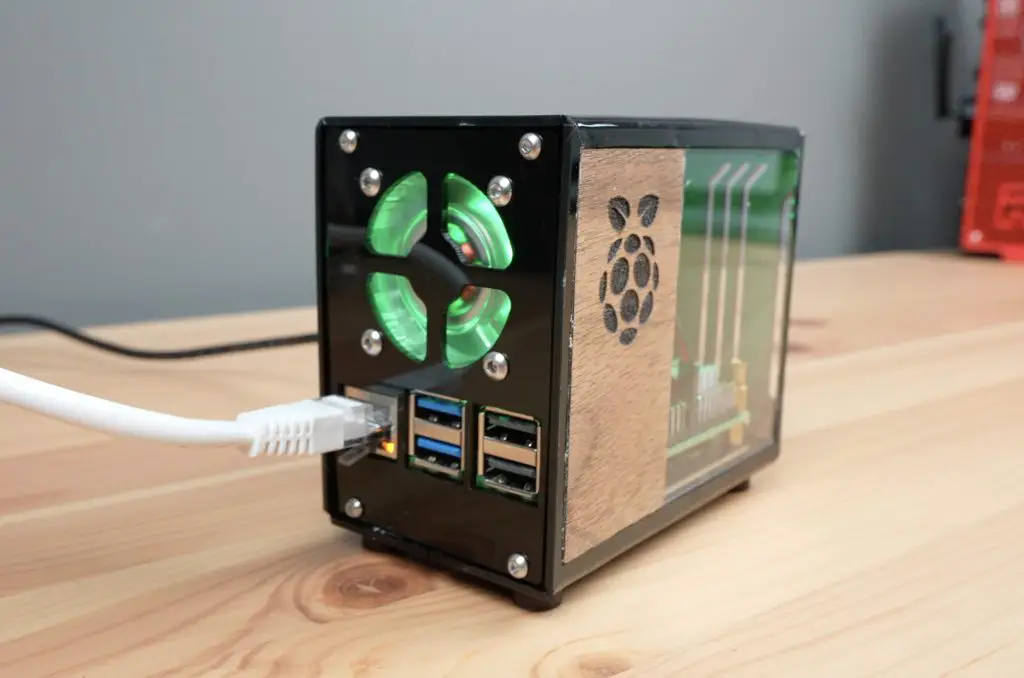
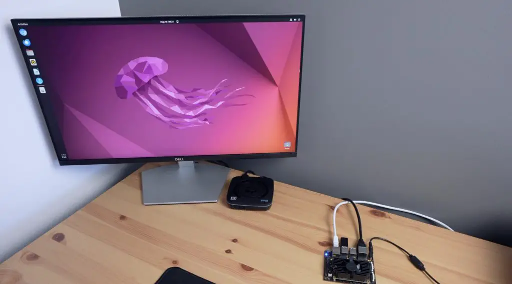
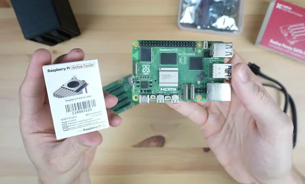
The cost of cloud services might not be that significant for one month, but the recurring costs quickly stack up. In a couple of years you can easily be out of pocket over a thousand dollars. So today we’re going to be building our own personal cloud server to bring these services in-house for a single upfront cost and take back full control of our own data.
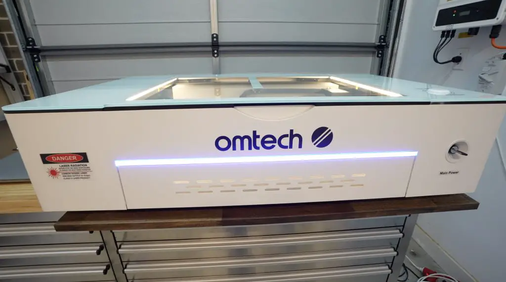
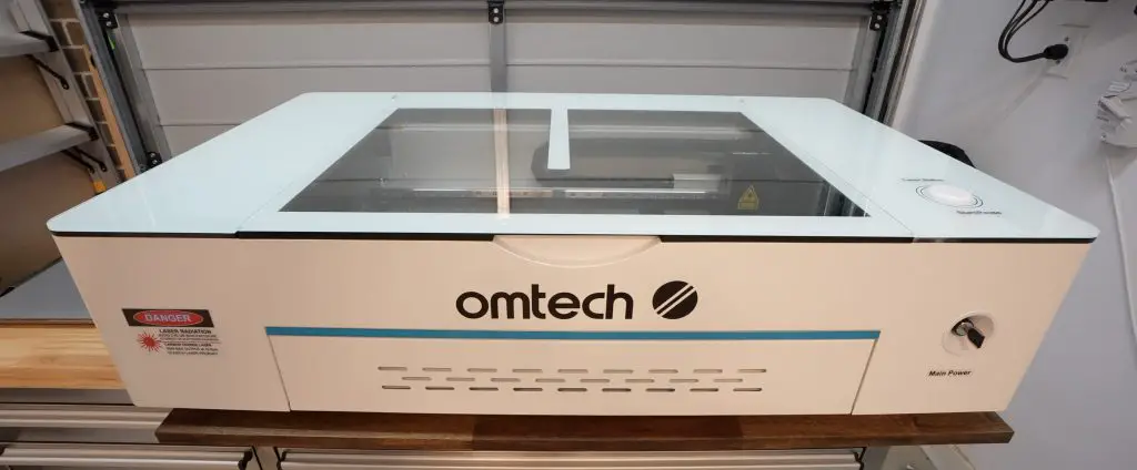
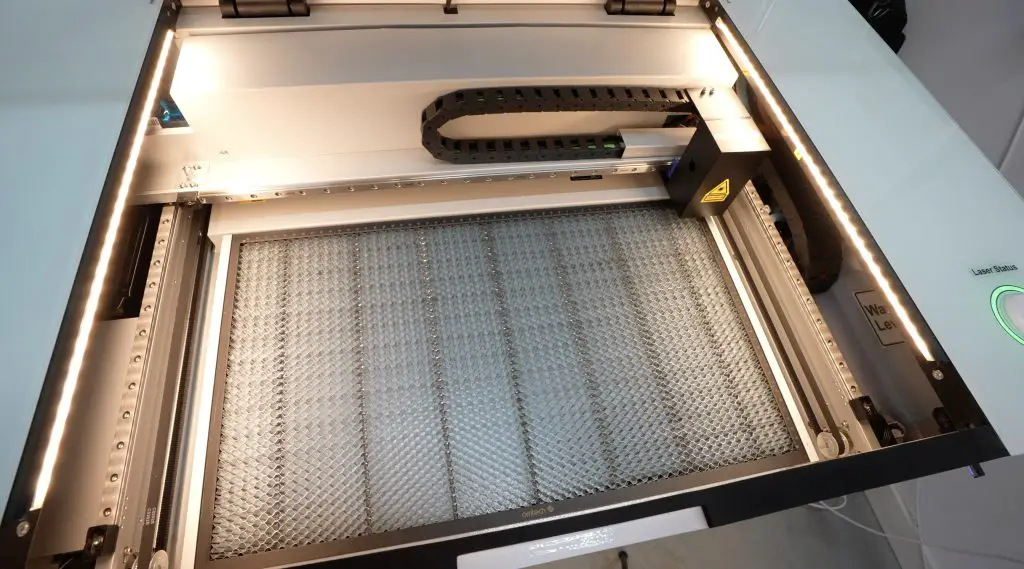
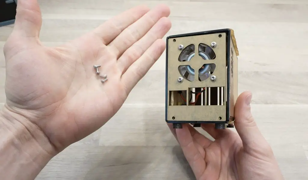
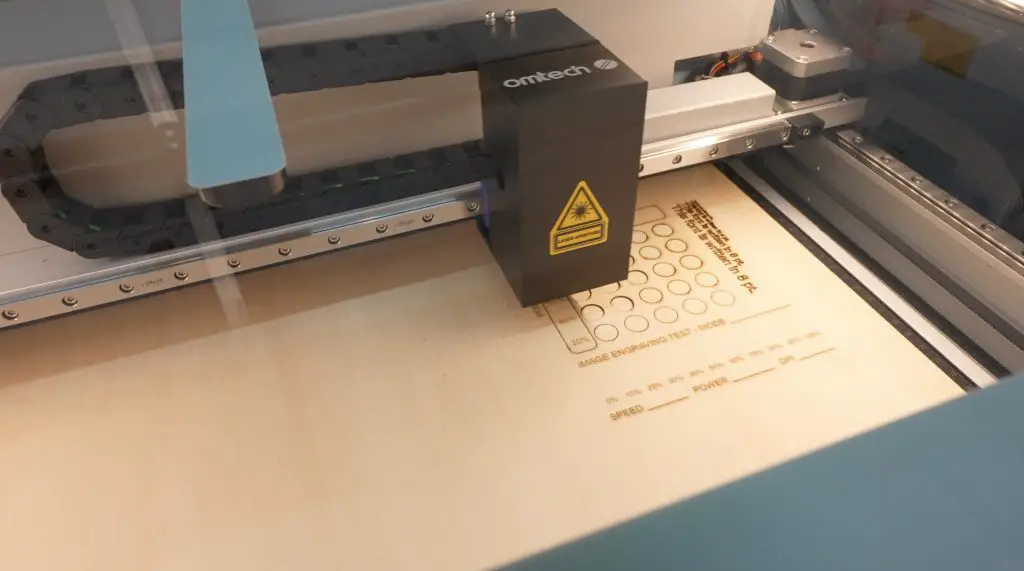
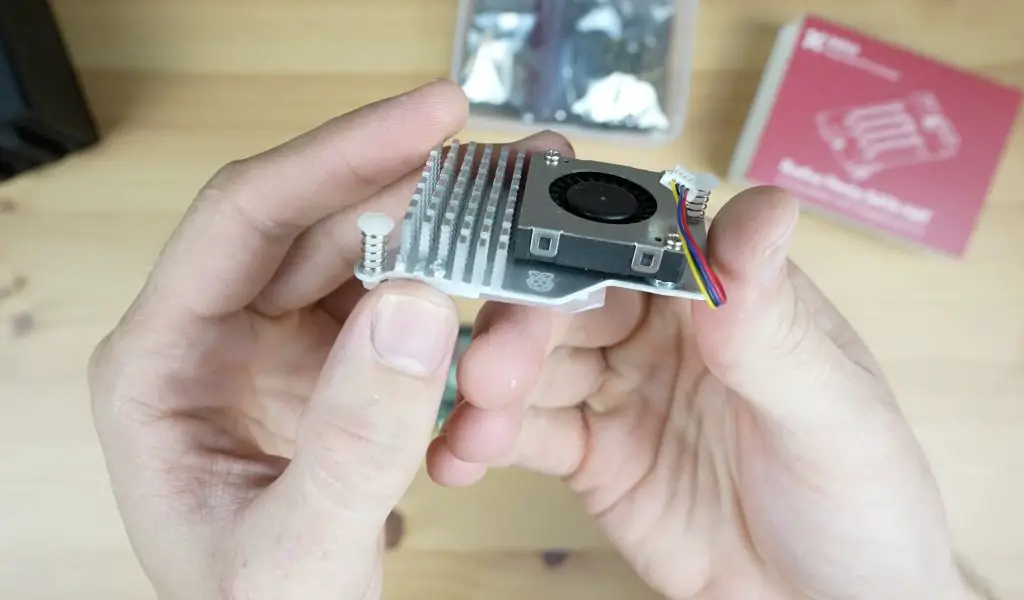
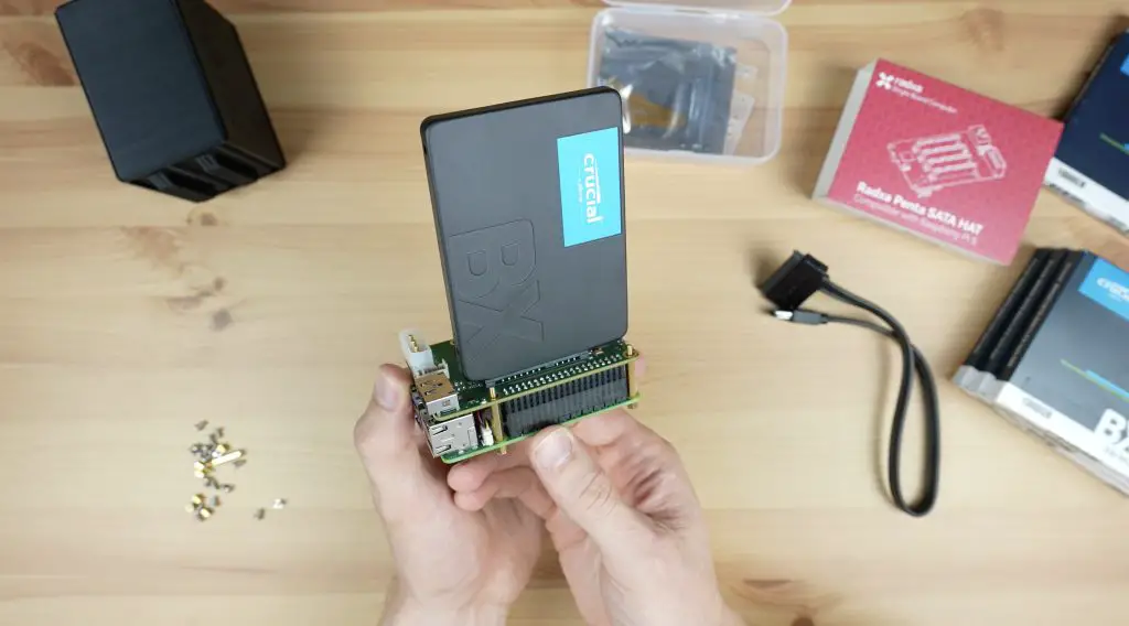
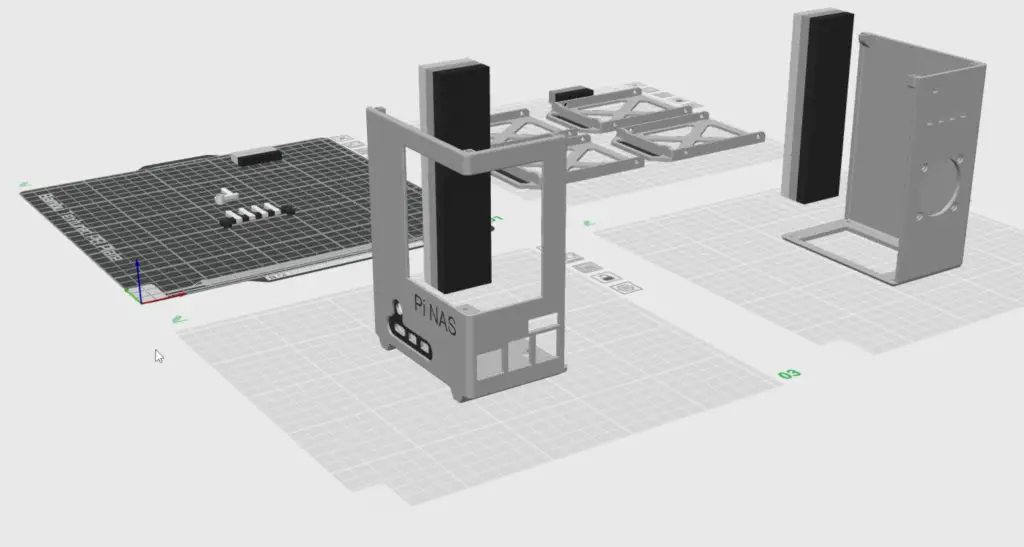
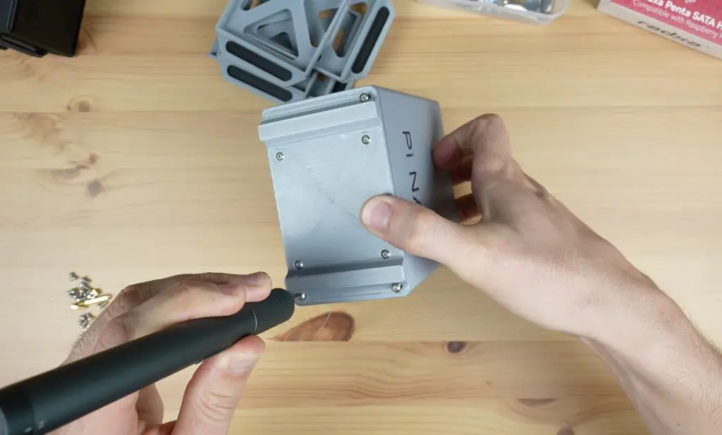
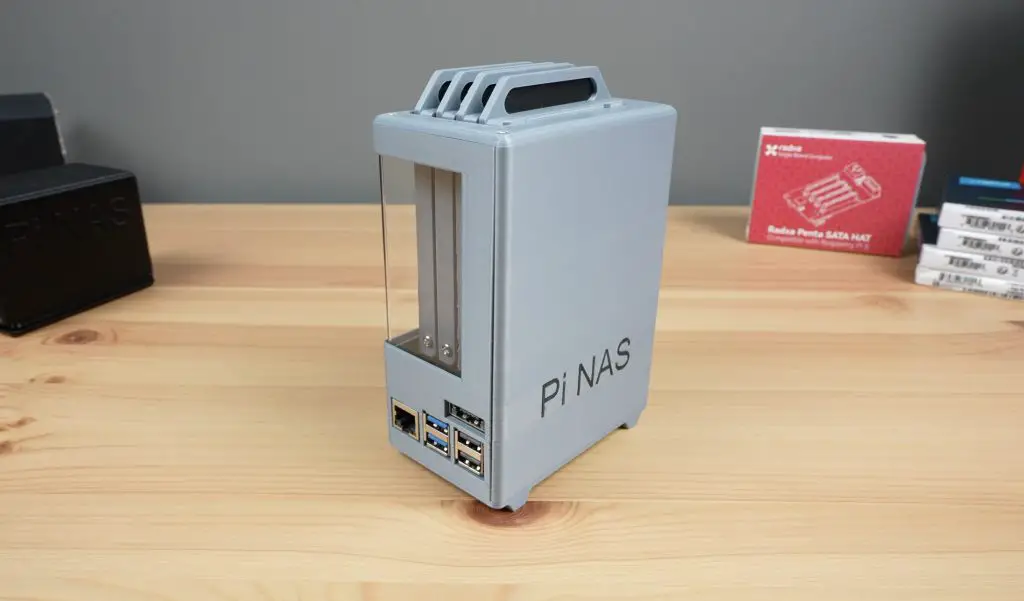
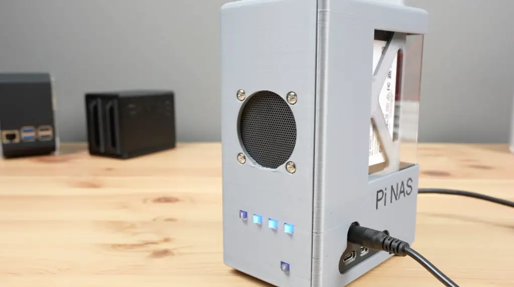
To do that we’re going to be using a Raspberry Pi 5 with an active cooler on it and a connected NVMe storage drive. To protect the Pi and drive, we’re also going to design and build a custom enclosure for it and I’ll be doing that using the Omtech Polar laser cutter and engraver.
Omtech sent me this new laser to tryout and share with you, so I thought the best way would be through a project that showcases its cutting and engraving capabilities on a range of materials.
Here’s my video of the build, read on for my written guide;
Components Required To Build Your Own Personal Cloud Server
To start, let’s get the Omtech Polar unboxed and set up.
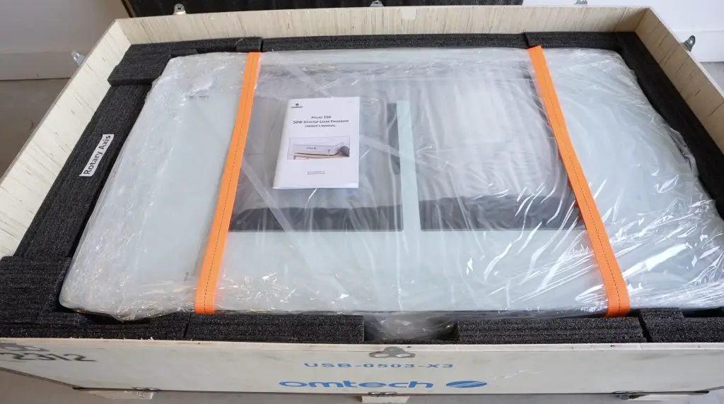
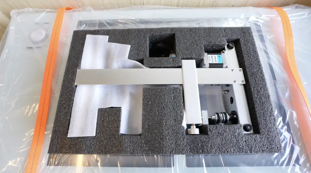
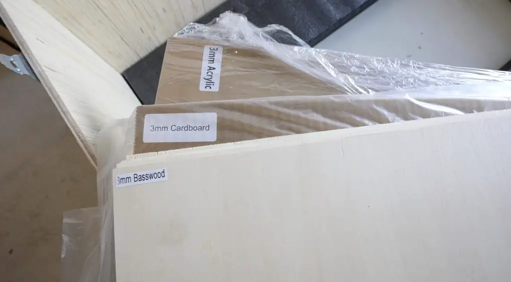
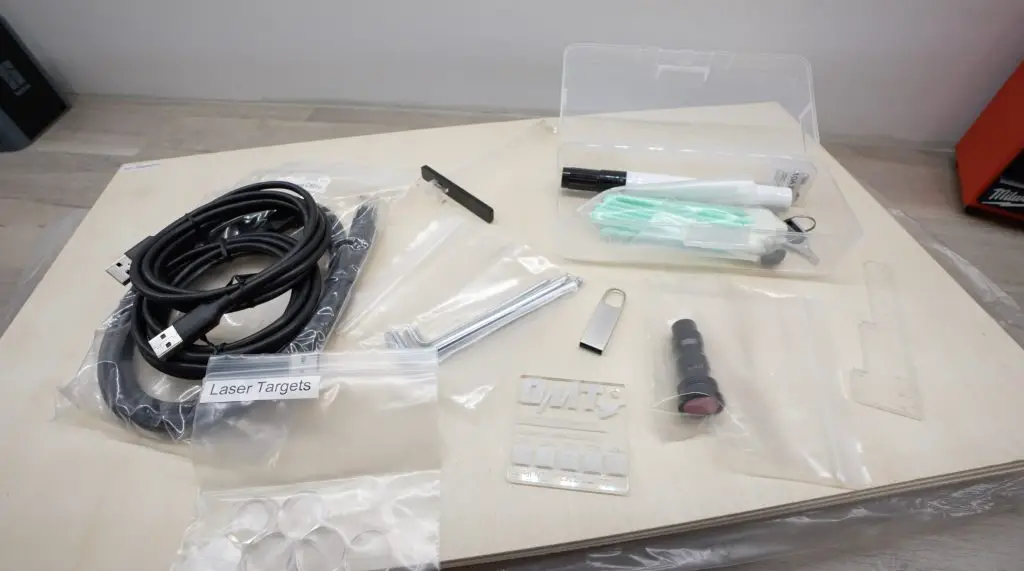
The Polar comes in a wooden crate and includes everything you need to get it set up and running. It even includes a rotary axis for engraving cylindrical objects and a materials pack to help you get started with some basic projects.
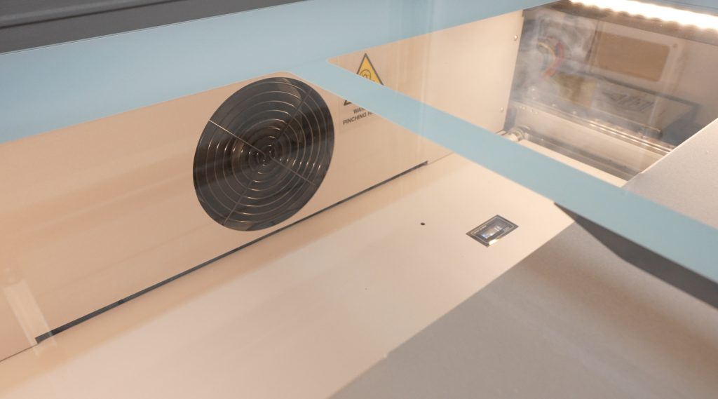
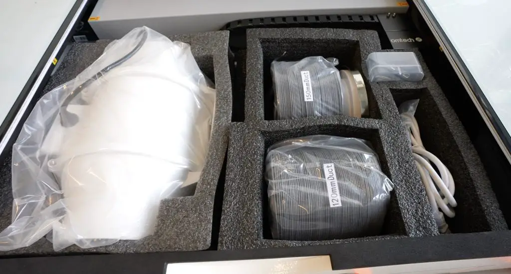
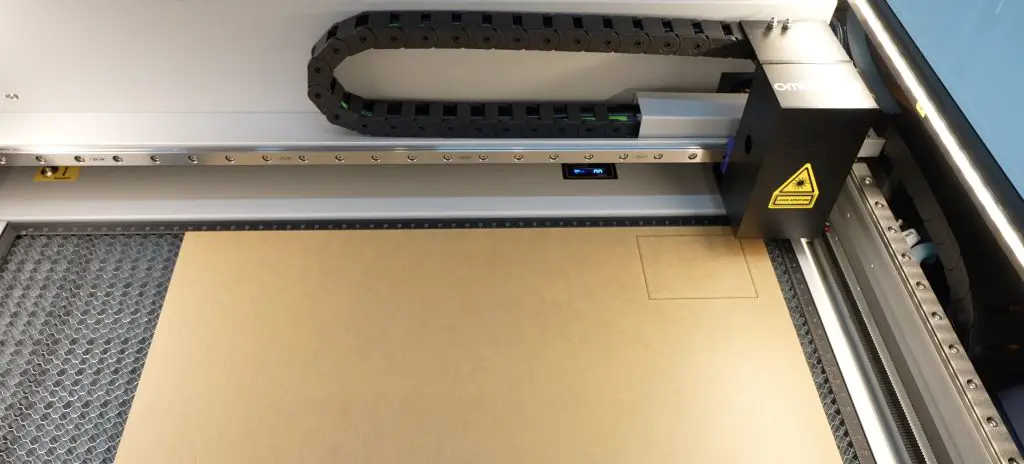
It is a fully enclosed design that contains the smoke and fumes while cutting and engraving, so it includes a ducted ventilation system to draw the smoke out of the machine and exhaust it outside. The full enclosure is also much safer for the operator than more common open gantry-style lasers.
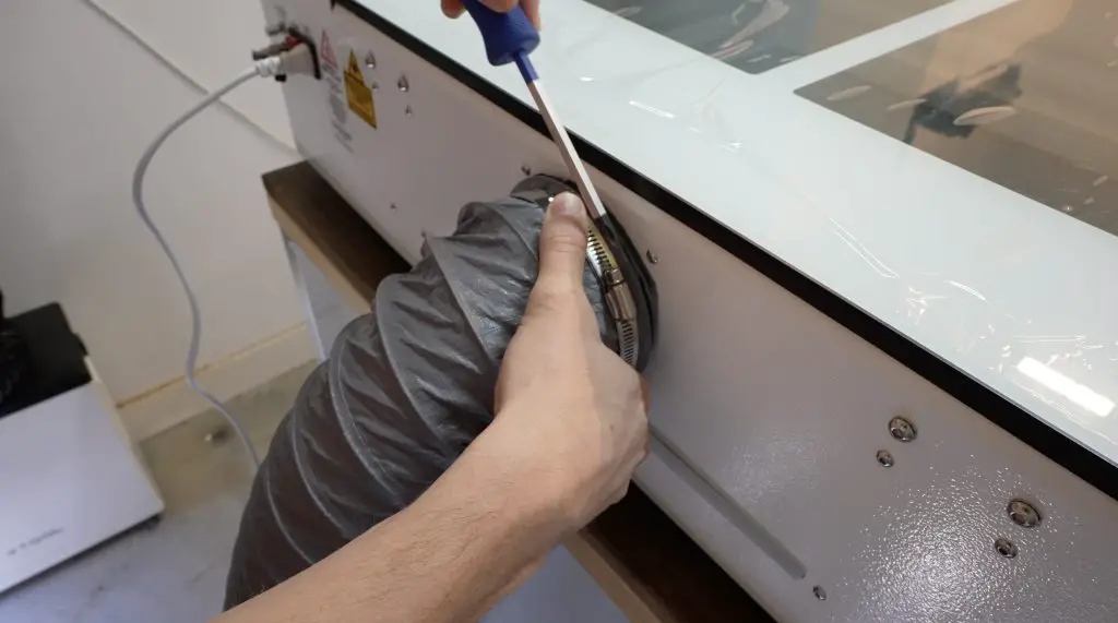
The Omtech Polar doesn’t require much in terms of setup. It comes pre-assembled, so all you need to do is connect the ventilation system to the back and connect it up to your computer via a usb cable or through your home network via Ethernet or WiFi.
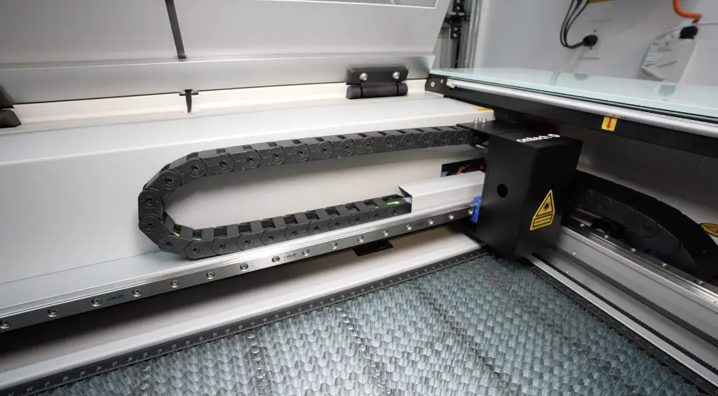
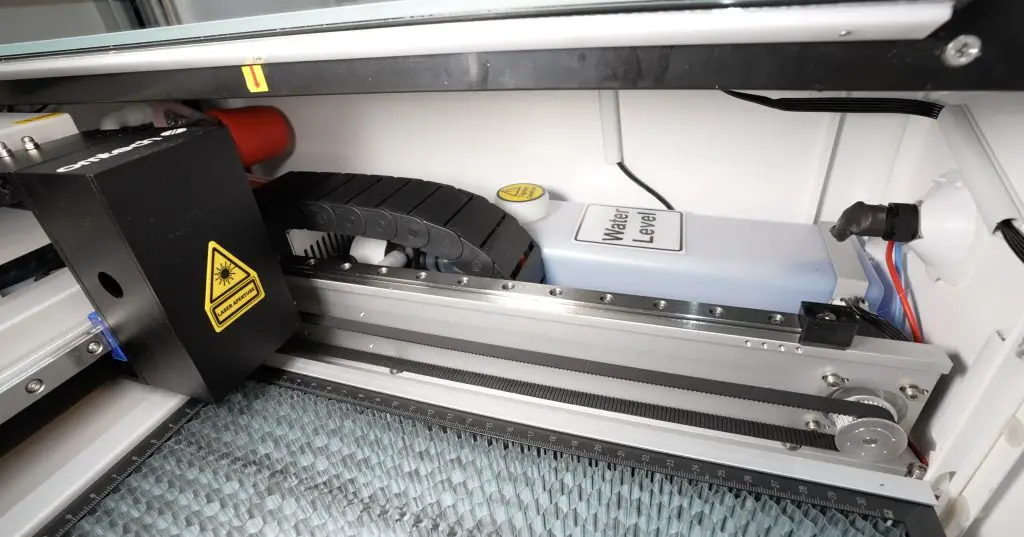
The build quality is also quite good. It’s an all-metal enclosure with a thick glass top and lid. Both axes run on linear rails and all of the cabling and air tubes run in a drag chain.
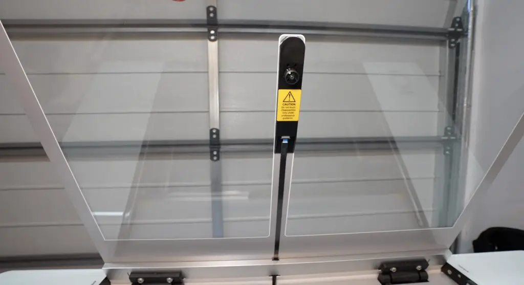
It also comes with some great features like integrated water cooling for the laser tube, built-in air assist and a 5MP camera to assist with positioning your artwork.
The working bed area is 500mm x 300mm, but it can accommodate larger materials using its pass-through tray.
Now that the Omtech Polar is set up, let’s get the case designed so that we’ve got something to cut and engrave on it.
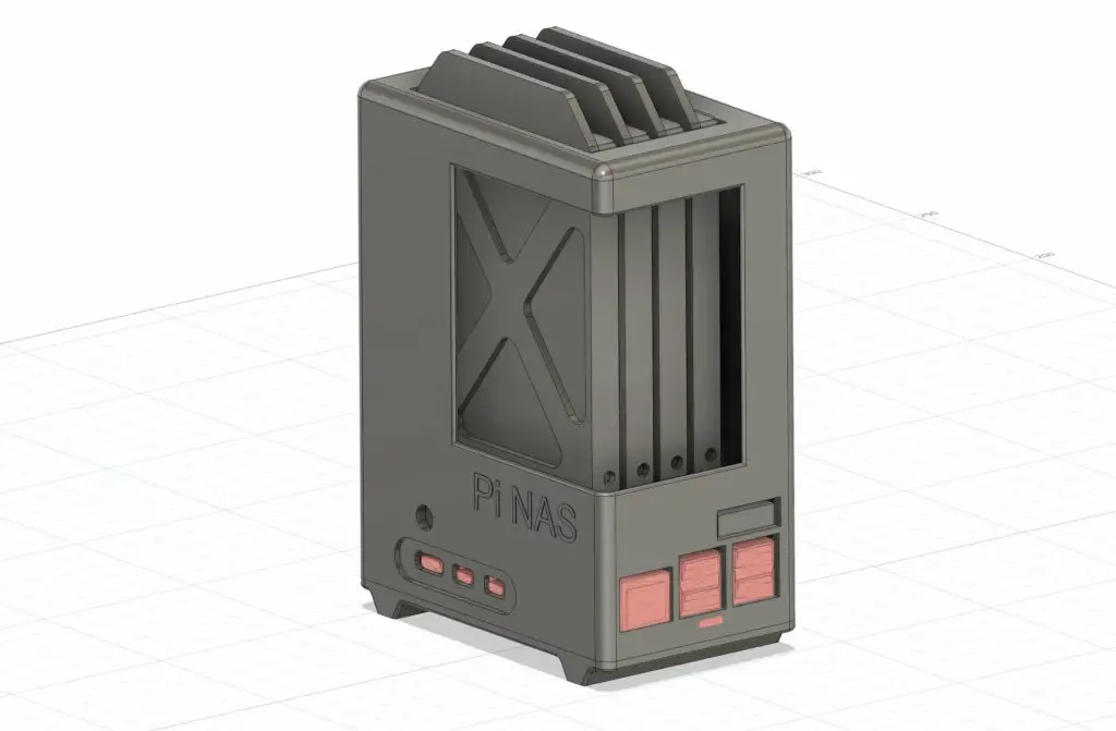
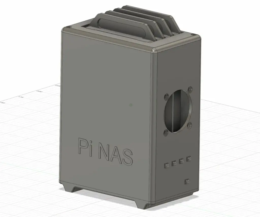
Designing The Cloud Server Case
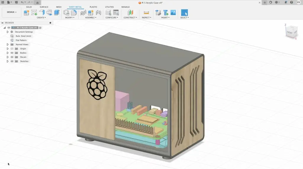
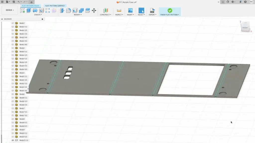
I used Fusion360 to draw up this case using the sheet metal designer.
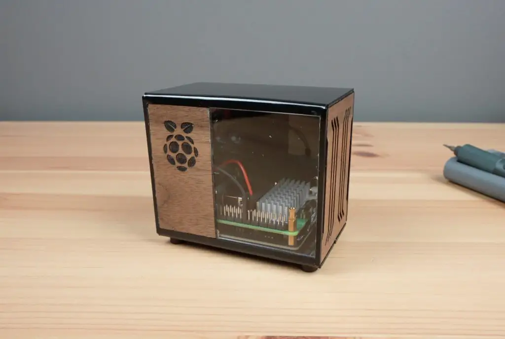
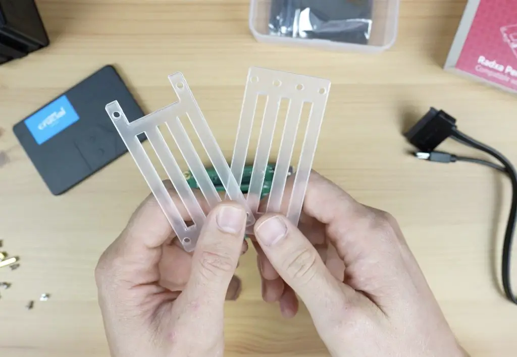
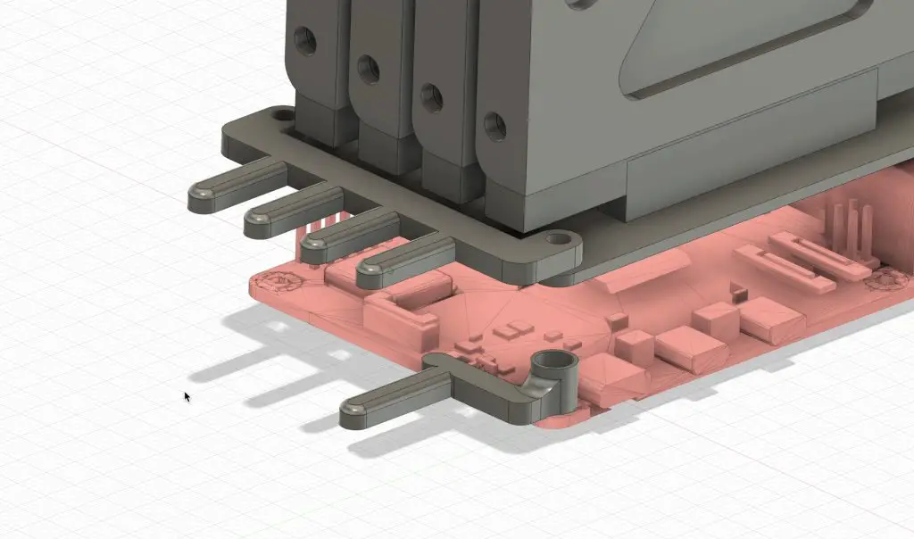
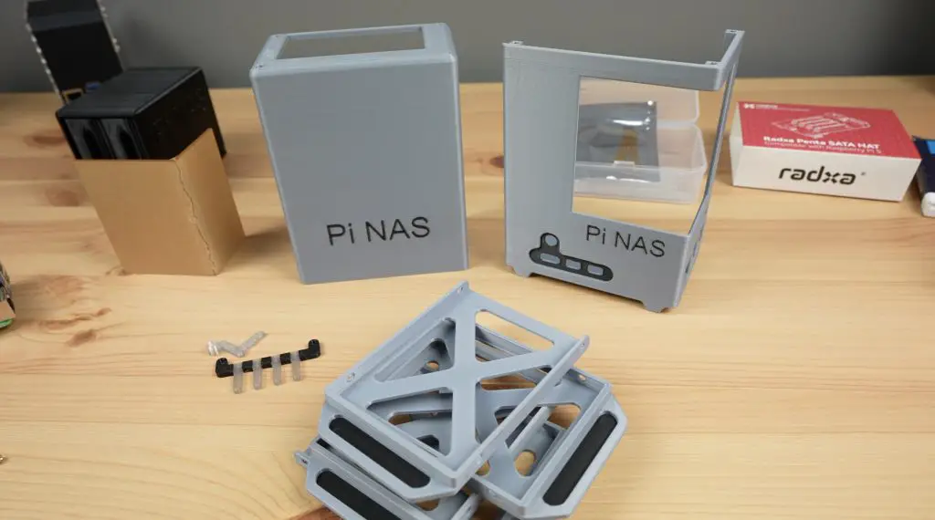
I chose this design feature so that we can open up the main body of the case into a flat pattern to cut out from a single piece of acrylic.
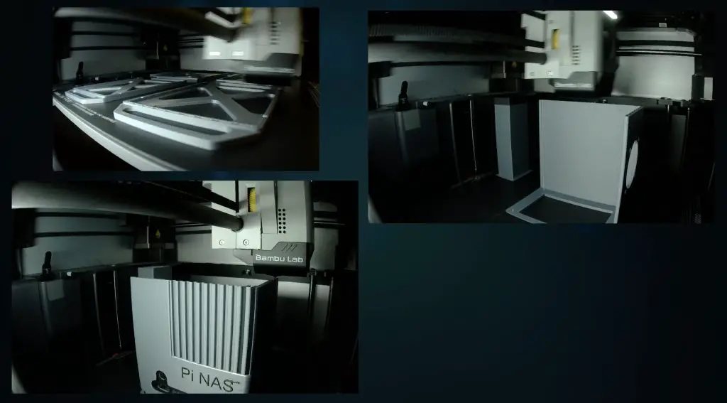
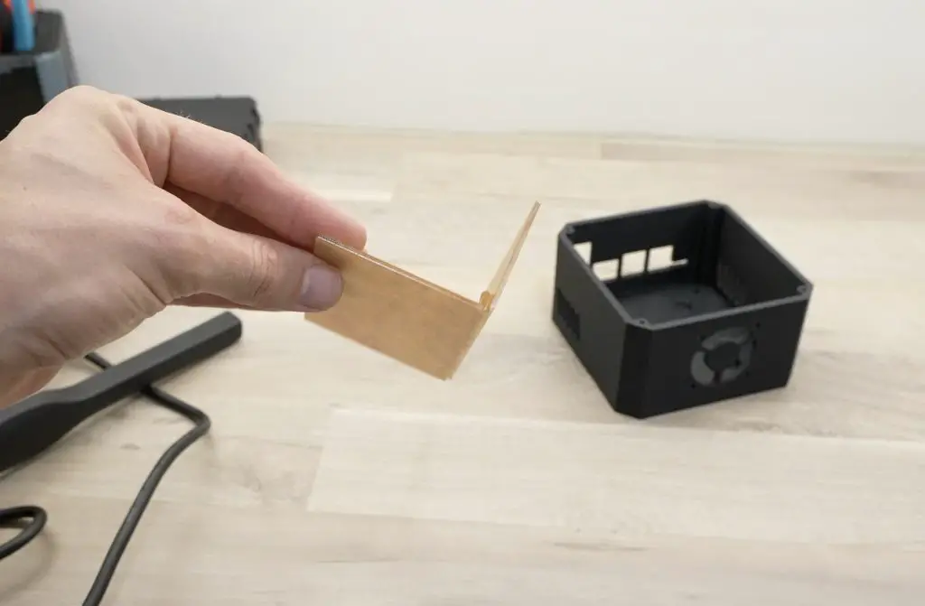
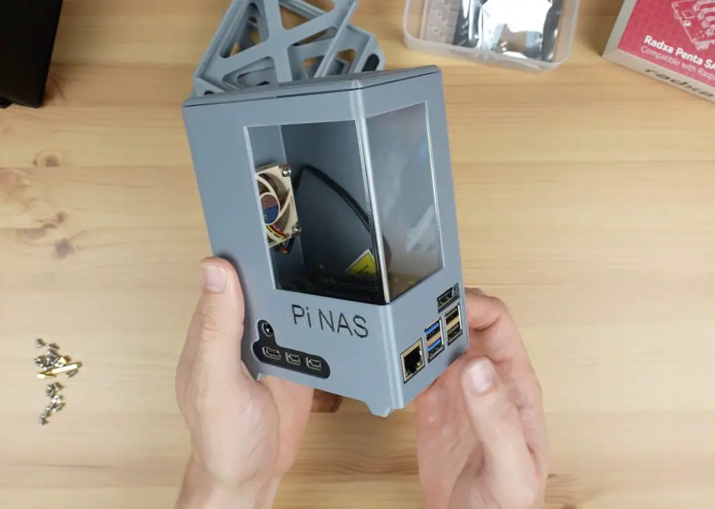
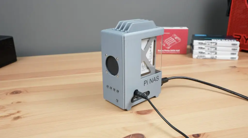
This sheet is then bent to form a rectangular tube and a front and back panel finish it off. I’ve also added a clear panel to one side and I’ll make the small side panel insert and the front panel out of walnut plywood as some accent pieces.
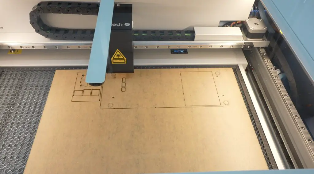
Making The Cloud Server Case
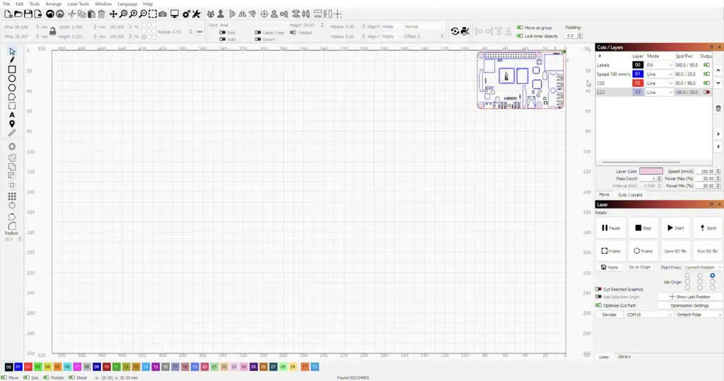
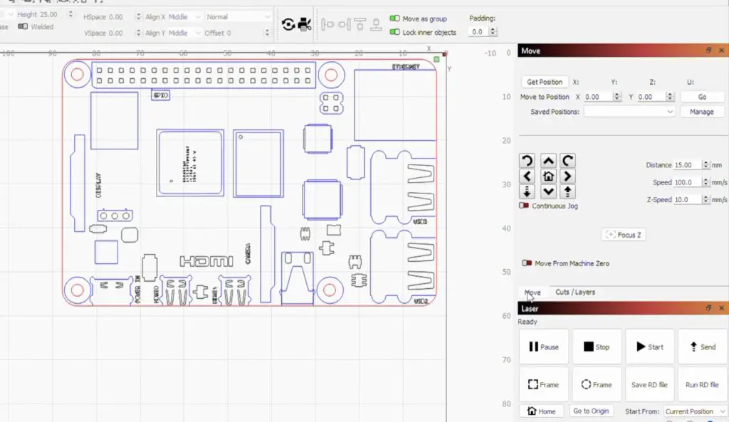
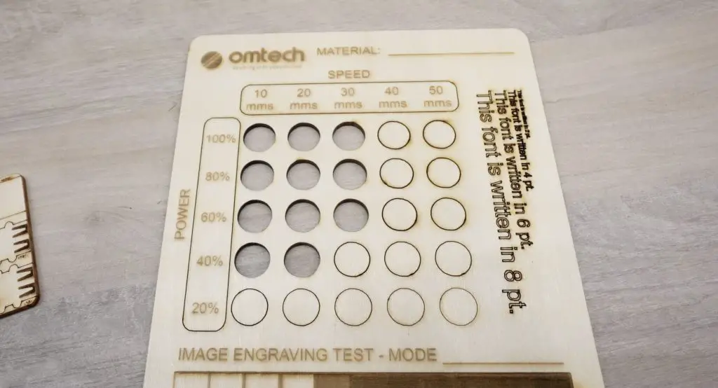
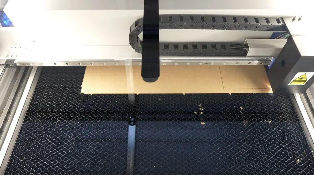
To cut out the components, I’m going to be using Lightburn to control the laser. Omtech include a copy of RDWorks with the Polar on a USB drive as a free option, but I already use Lightburn quite a lot on my other lasers, so I’m going to use it for this project too. It’s great that this is an option on the Polar as some systems like the Glowforge lock you into using their own proprietary cloud-based software with no alternatives.
Before running the laser, remember to always use proper certified protective eyewear suitable for your laser type when working with these machines, even fully enclosed ones.
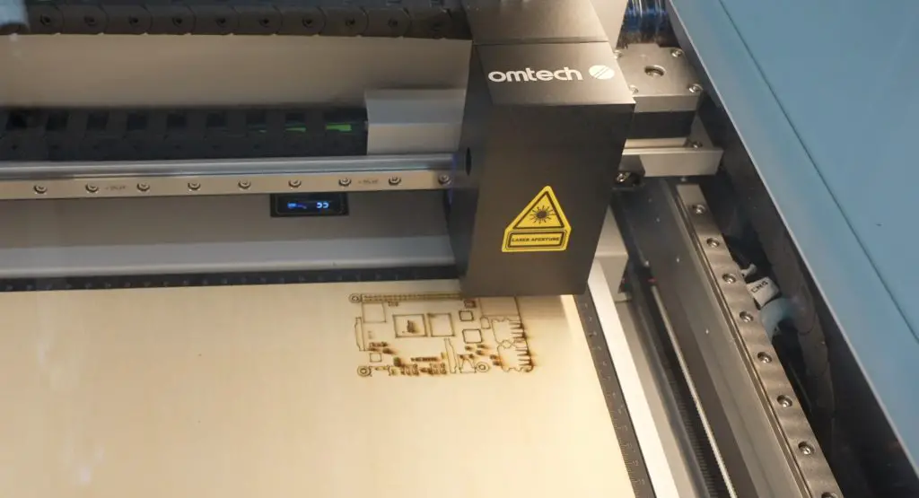
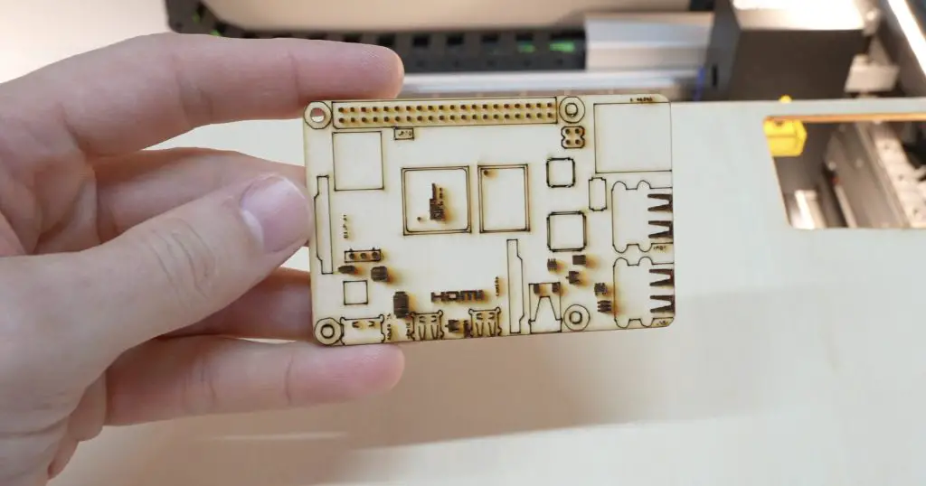
As a quick test to start with, let’s engrave and cut a dummy Raspberry Pi that I’ll use to test fit the case’s bends.
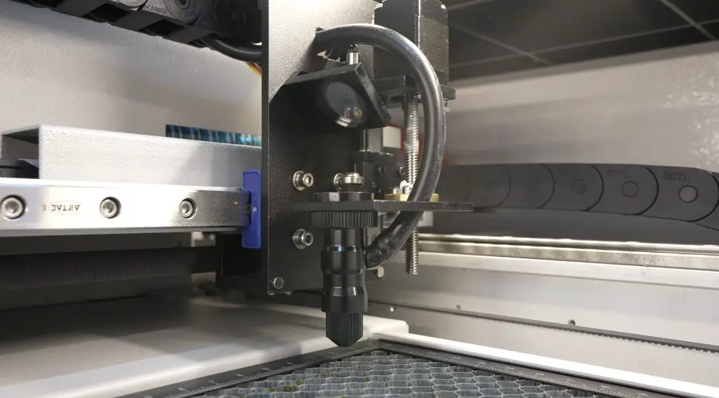
The Omtech Polar has a somewhat automated focusing system. You focus the laser using the distance parameter in Lightburn which tells the laser how high to position the head above the material. When set to 17mm, the laser focuses on the surface of the work bed. You then subtract the material thickness from this to get the focus height. I’m using 3mm plywood for the test piece, so the focus height needs to be set to 14mm.
The quality of the cuts and engraves is pretty good, although it doesn’t seem like there is a way to turn the air assist off through software or hardware. This means that the engraving smoke is blown down onto the surface of the wood, which leaves the smoke marks you can see around the engravings.
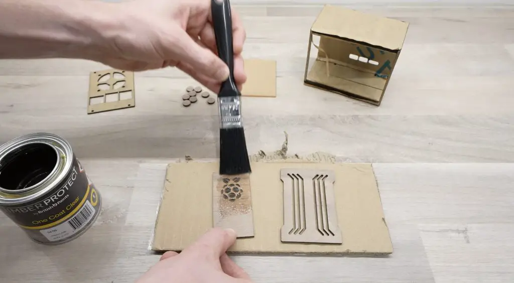
I’ll use masking tape on the engraved wooden side panel to stop this when we engrave the Pi logo.
The main enclosure flat pattern and back panel are cut from 2mm black acrylic.
Then let’s cut the window from some 2mm clear acrylic.
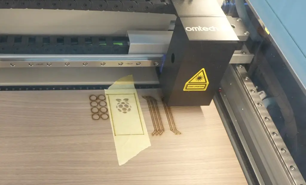
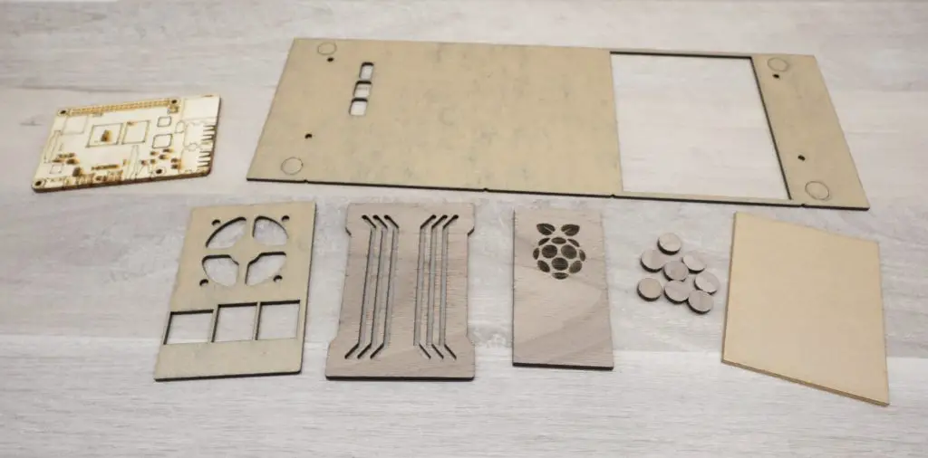
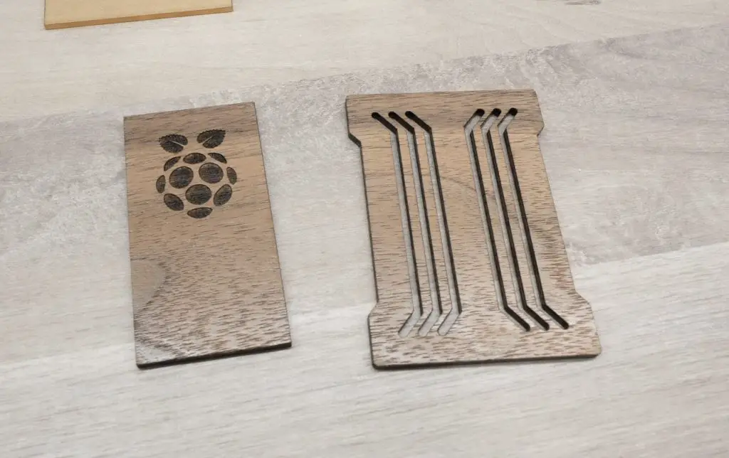
Lastly, we can cut the front and accent panel from a piece of walnut plywood. It’ll engrave the Raspberry Pi logo onto the side panel before cutting the panels out. I’ve put masking tape over the area where the Pi logo is going to be engraved so that the engraving smoke doesn’t mark it.
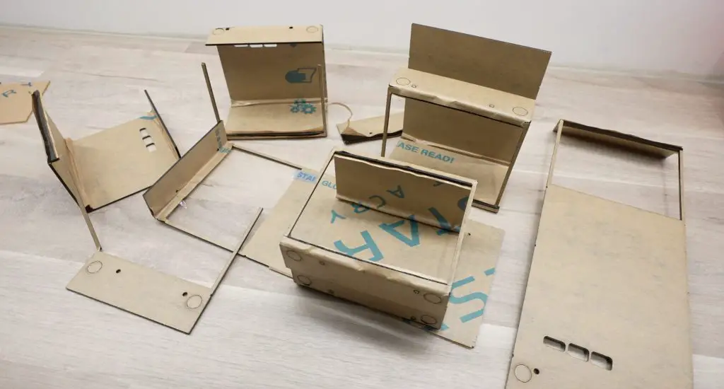
Now we’ve got all of the case components made up.
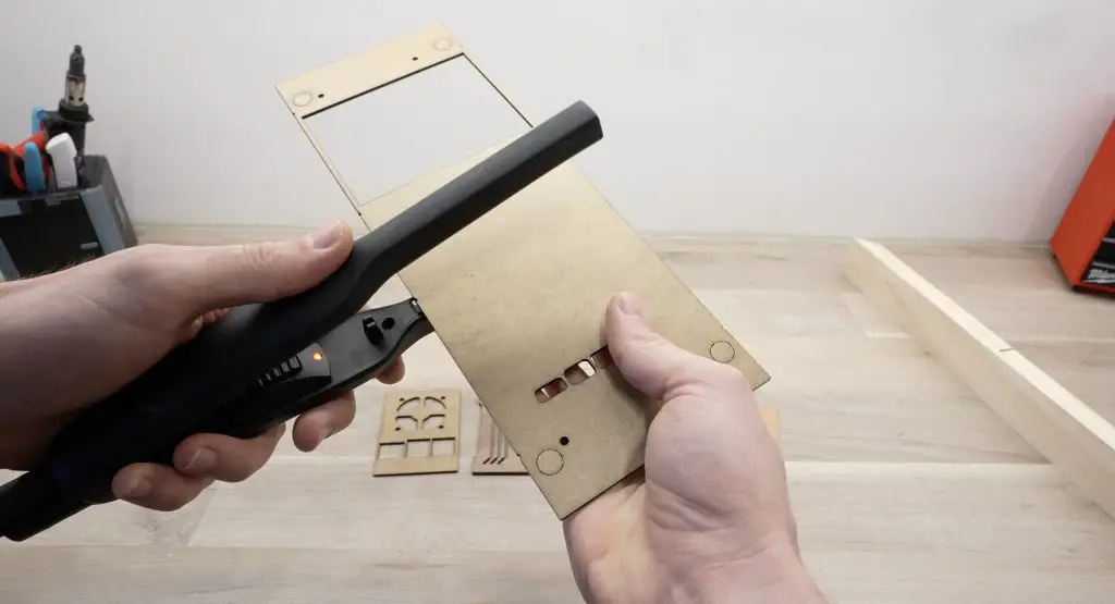
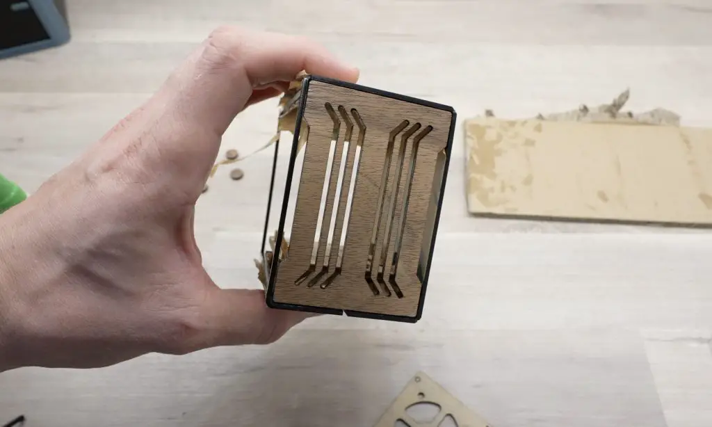
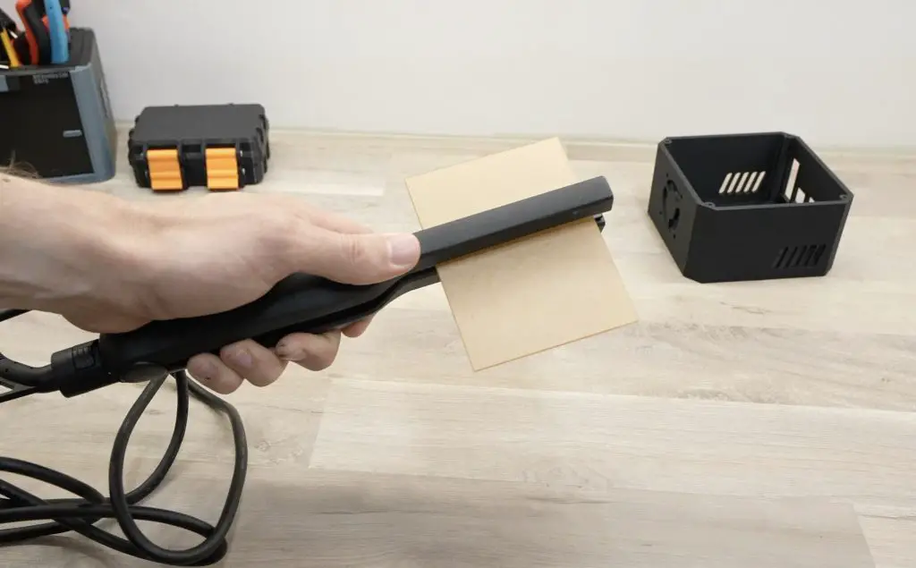
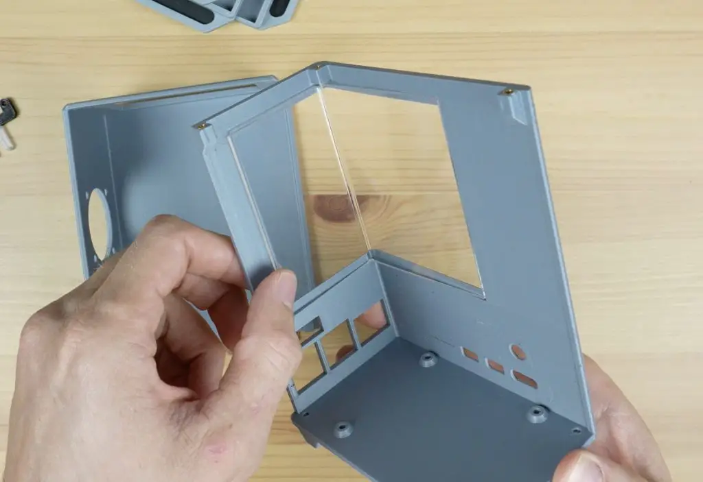
To bend the acrylic I’m using an acrylic bending tool, I’ve added little notches to the flat pattern as guides for the bend lines.
I know it looks like a hair straightener but you can get these bending tools from Aliexpress for about $15 (or from Amazon for a little more) and they work well for bending small sections of acrylic.
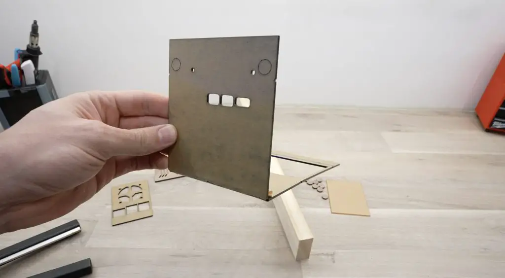
With the four sides bent, it’s starting to look like a Pi case.
I’m not going to pretend that I got this right on my first go, actually far from it. I cut this flat pattern out about 8 times before I got the bends in the right places without breaking one of the thin sides alongside the clear window.
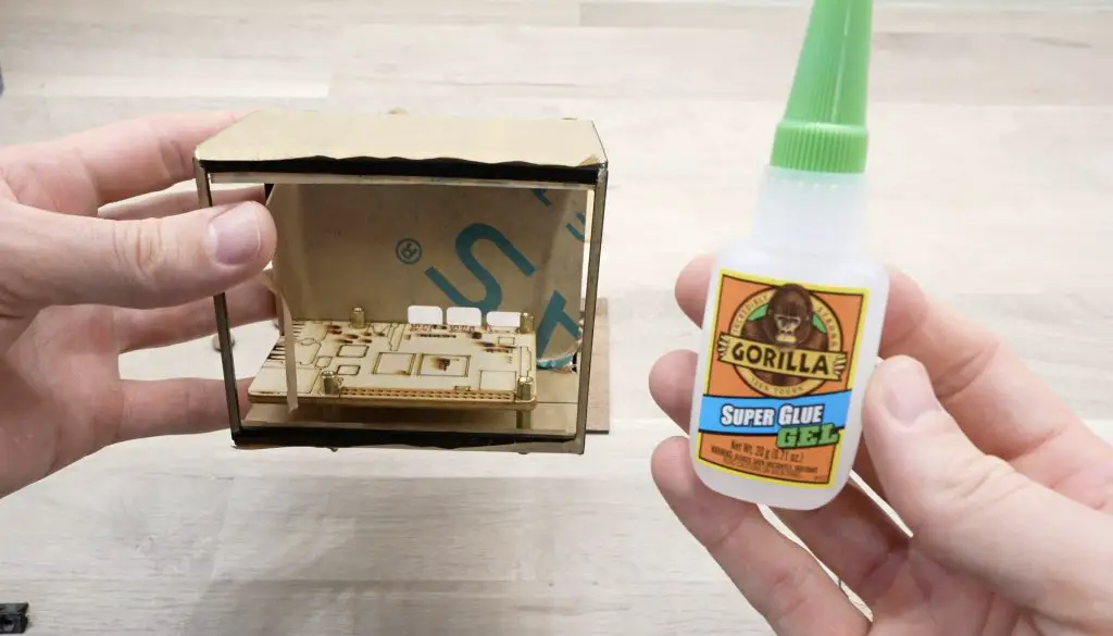
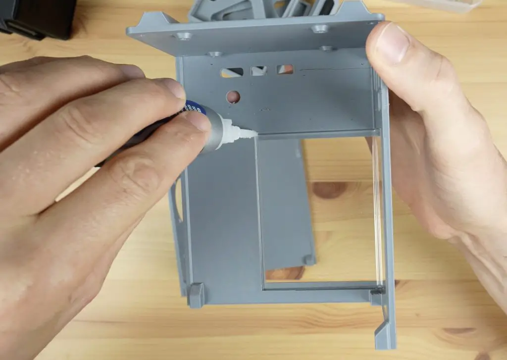
Next, I’m going to give the walnut panels a quick coat of varnish to bring out their colour and seal them before gluing them into place.
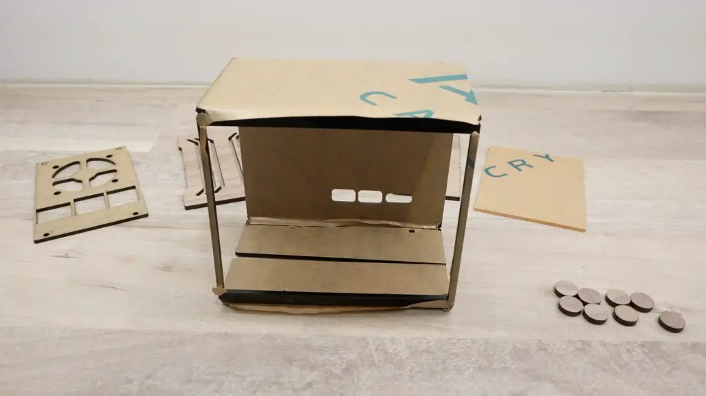
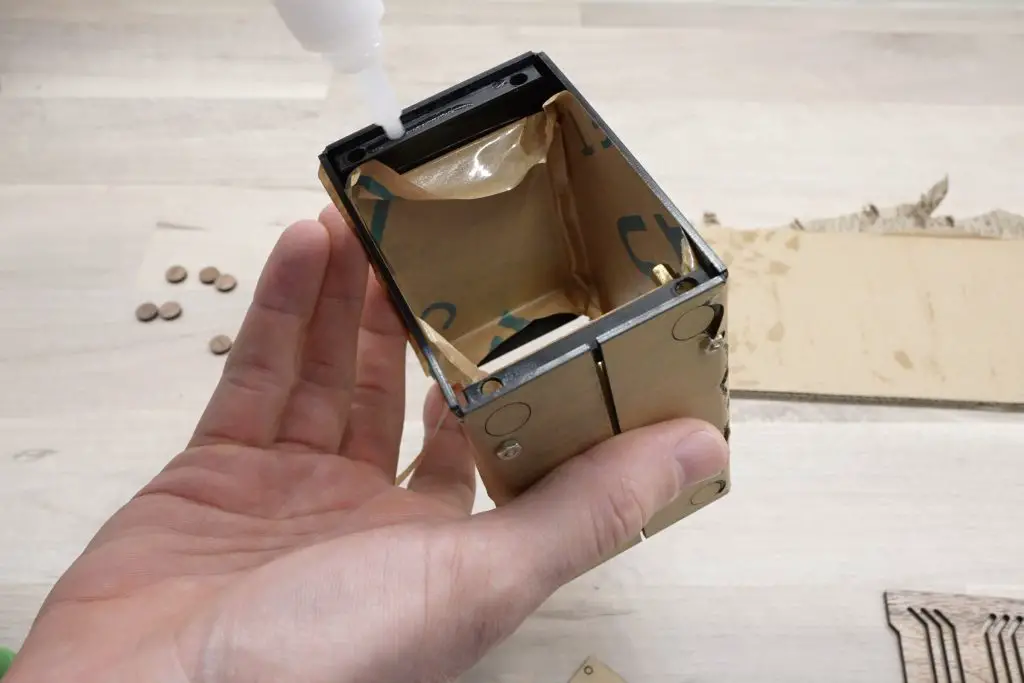
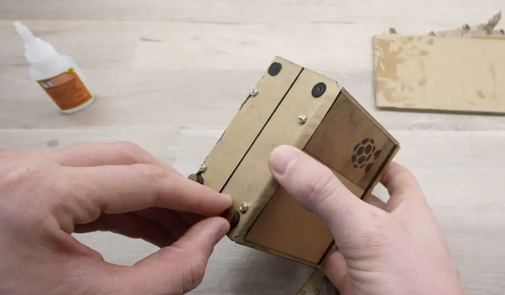
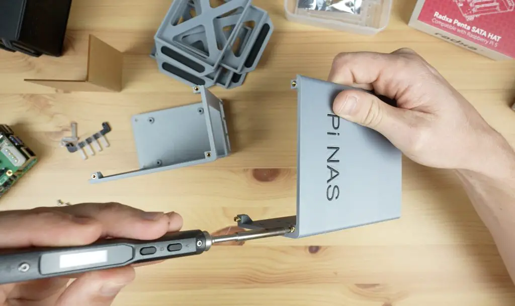
Then to finish the case off, we can glue the front section and side panels into place with some superglue. I’ve mounted the dummy Pi into the case while doing the front panel to help with alignment.
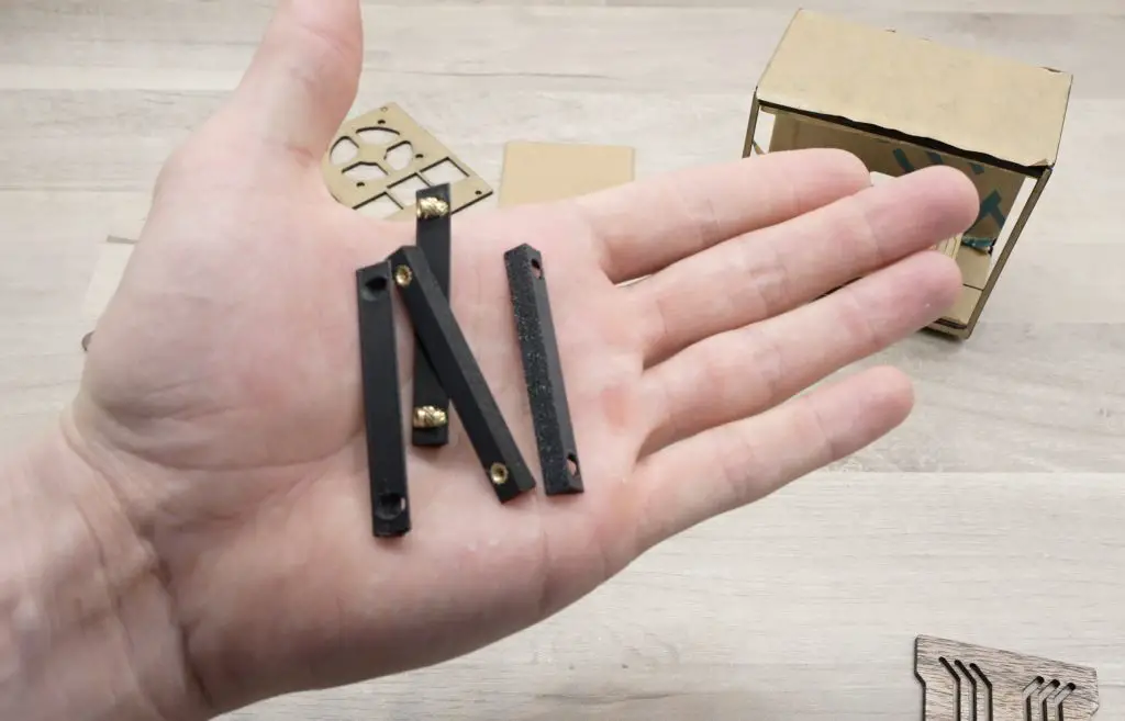
I’ve also 3D printed some small 90-degree pieces to help with supporting the front and back panels.
I’ve also glued the feet onto the bottom, using two of the feet circular cutouts to make up each complete foot.
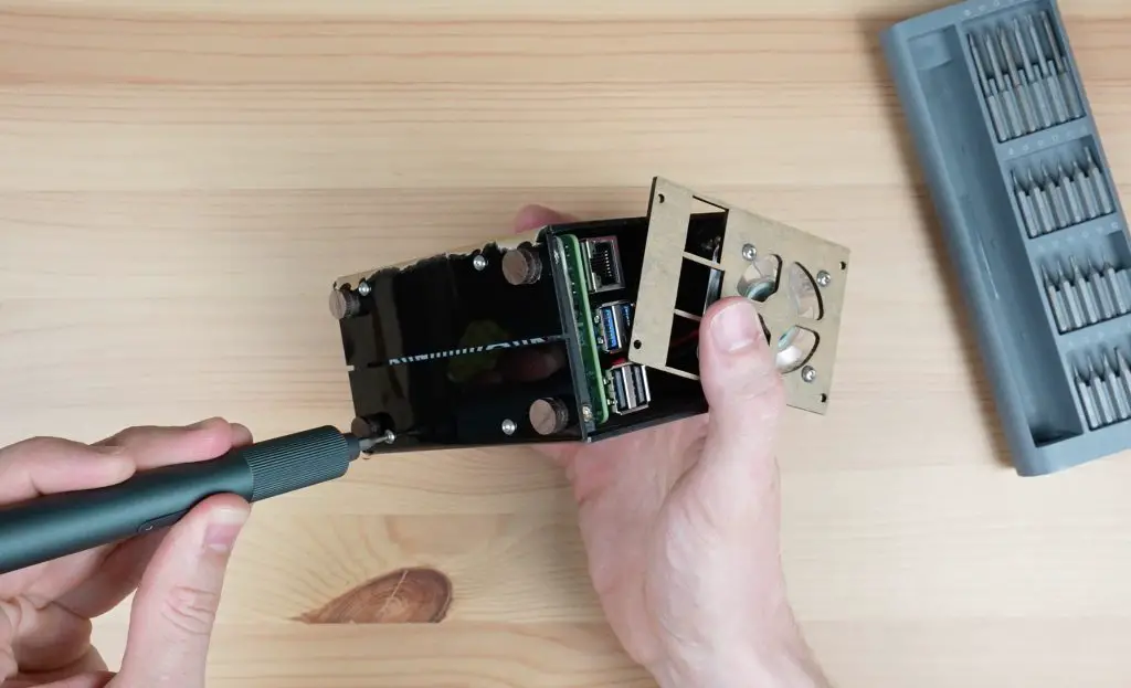
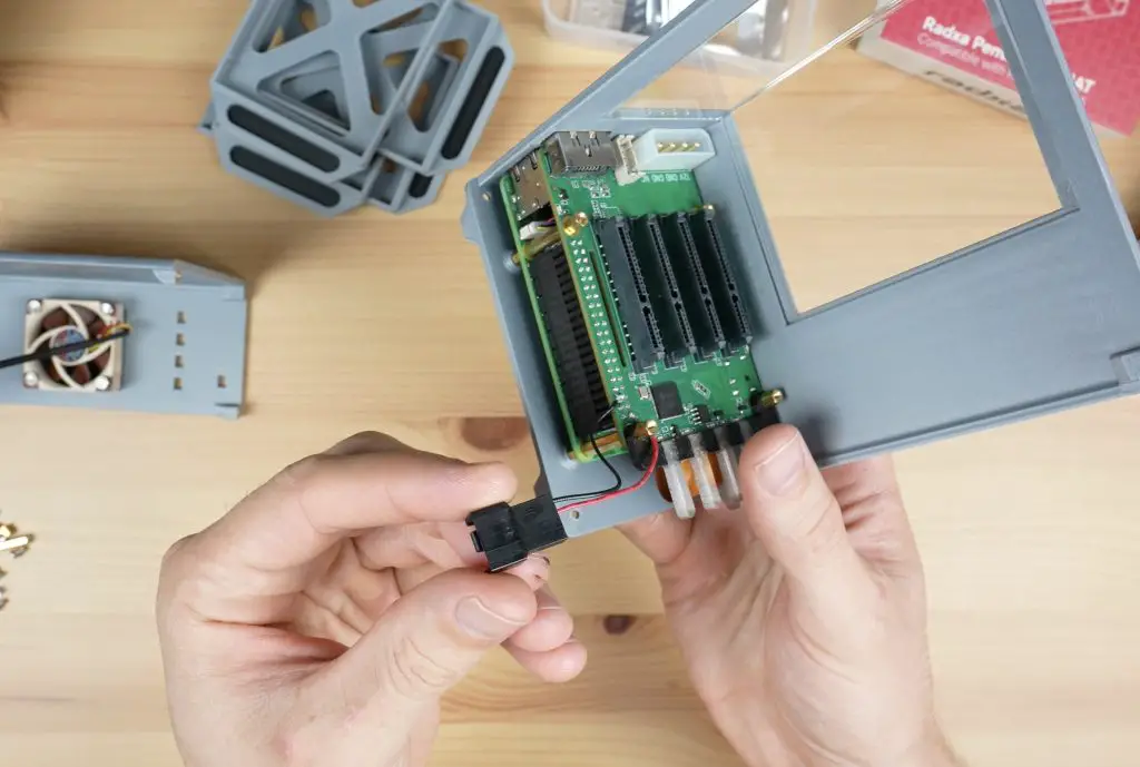
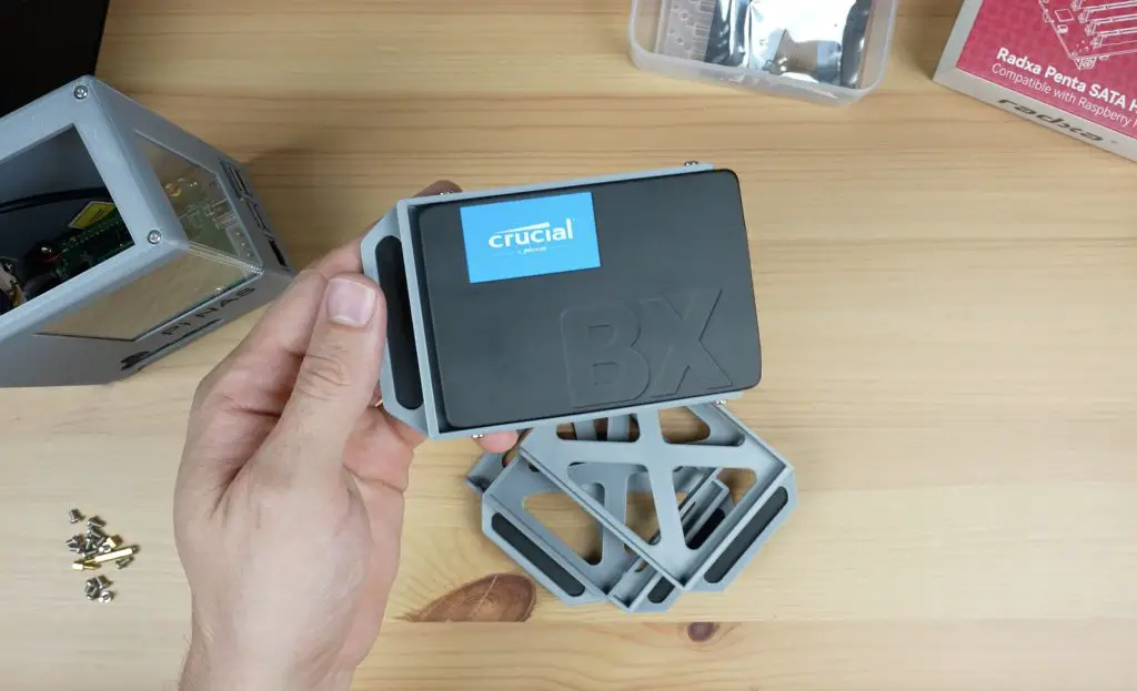
The back panel is held in place with some brass inserts in the 3D-printed parts and M2.5 button head screws to secure it. This panel has to be removable to get the Pi in and out of the case.
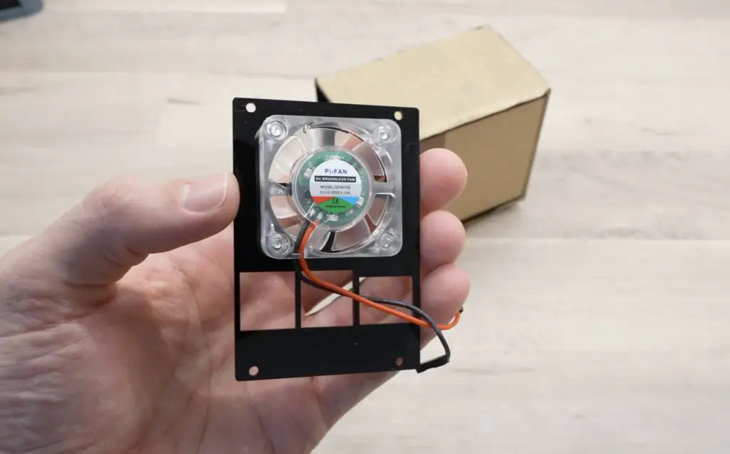
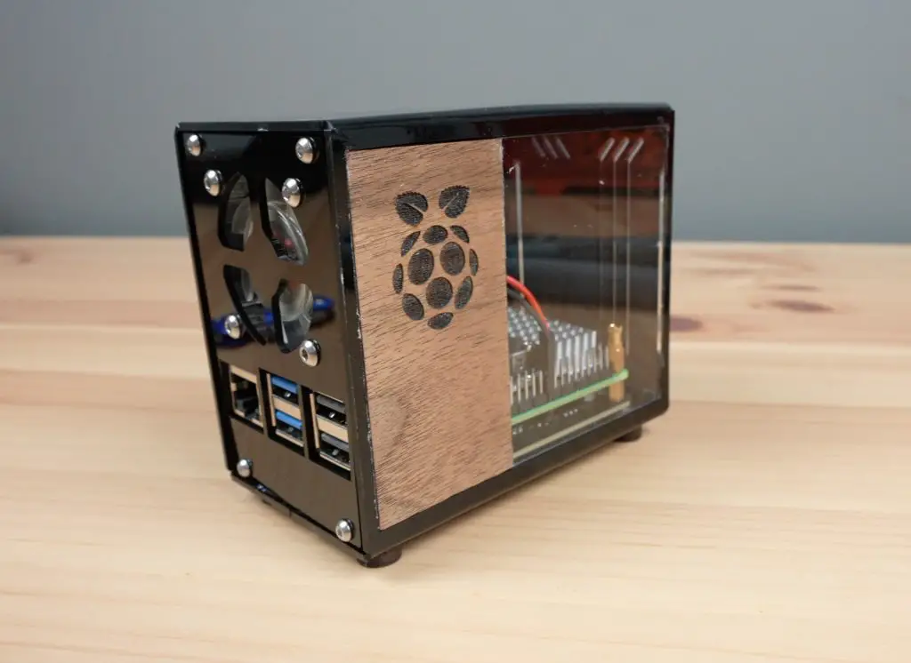
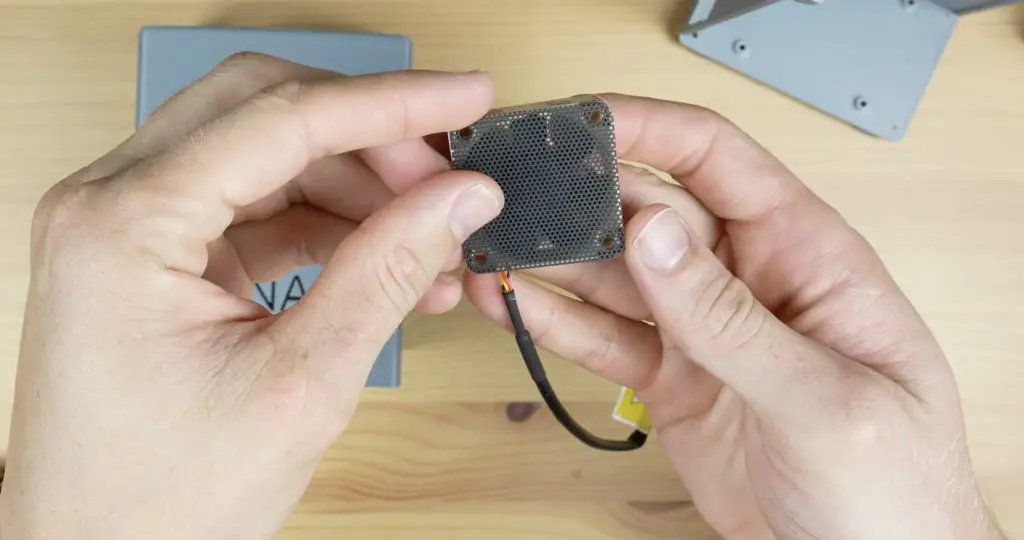
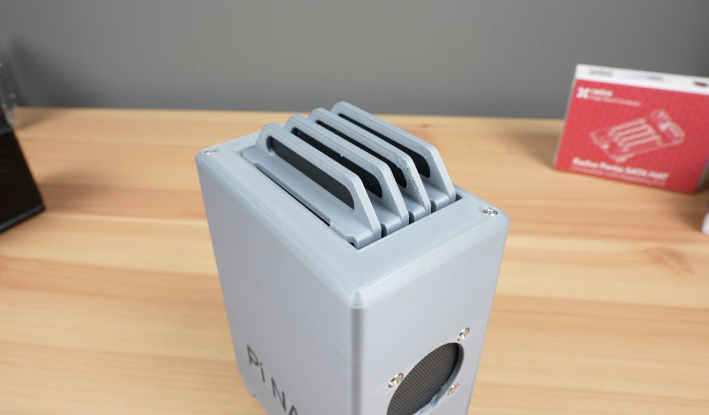
I’ve also added a 40mm fan to the back panel to push air into the case and out of the vents at the front. This is held in place with some M3 button head screws and M3 nuts.
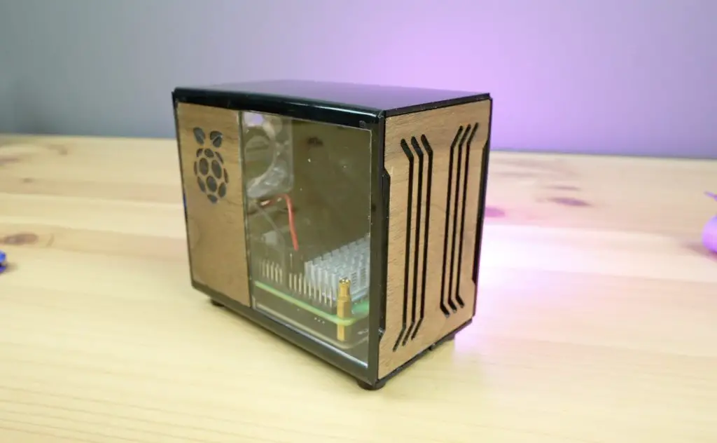
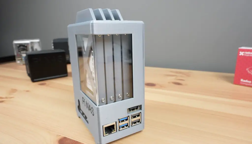
And that’s the case complete, now we just need to install our Pi stack and load our software onto it to turn it into our personal cloud server.
Installing The Pi 5 and Software
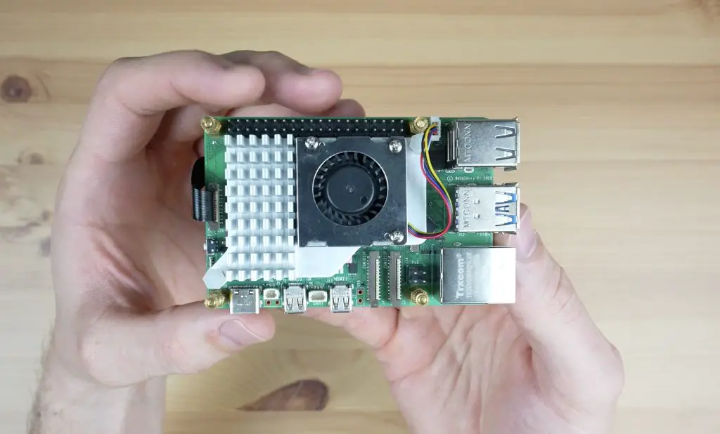
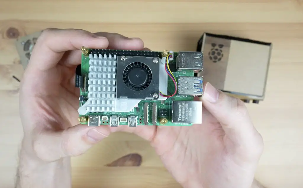
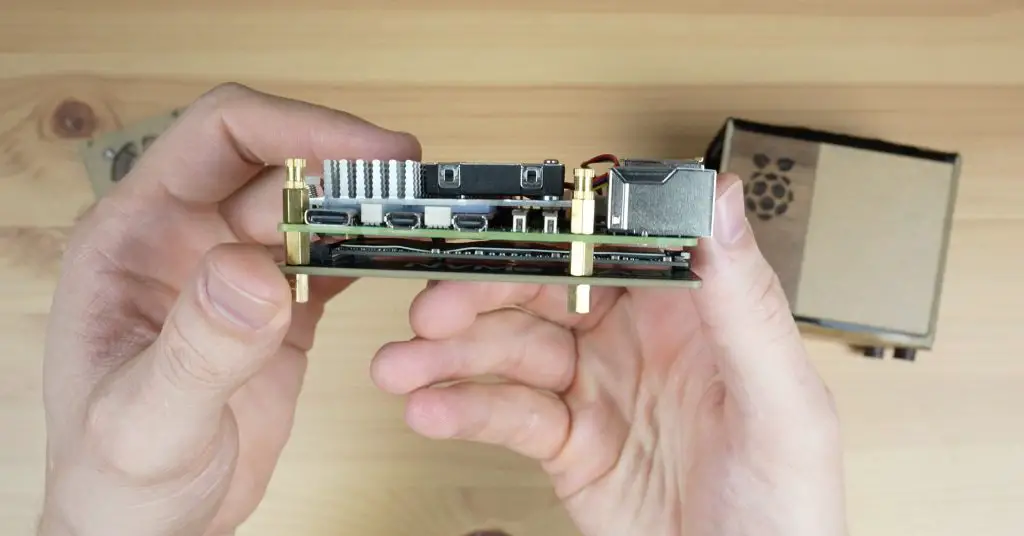
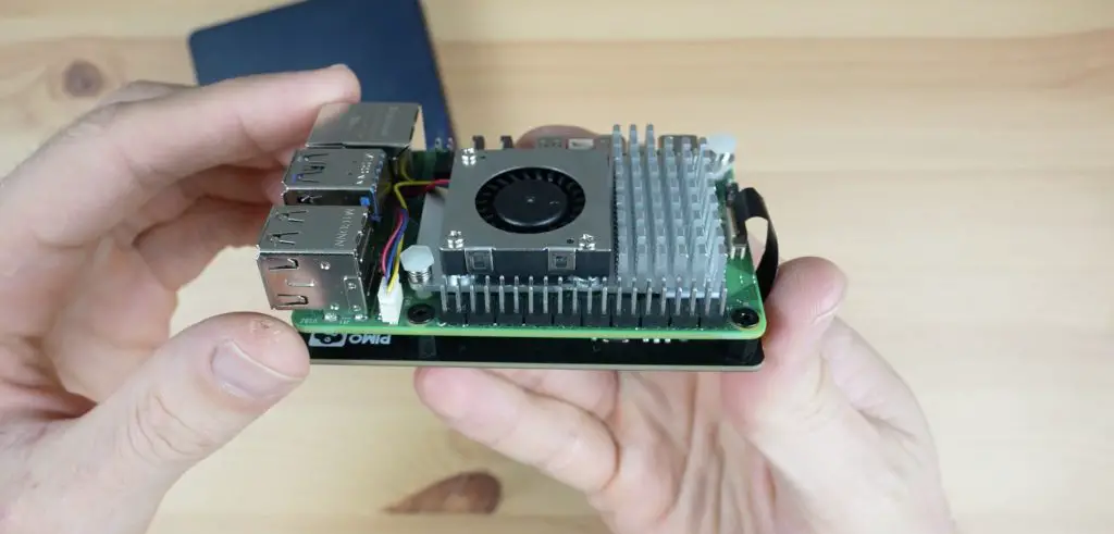
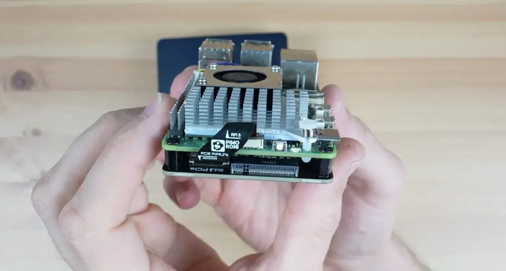
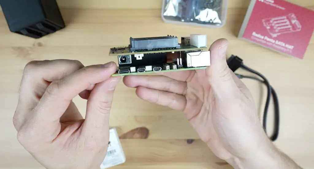
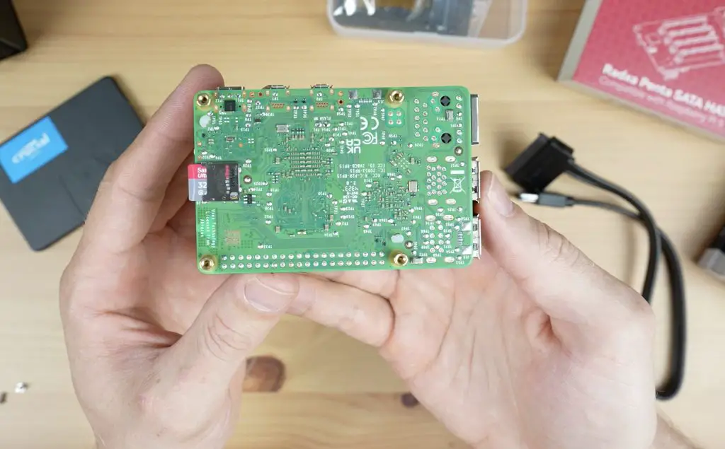
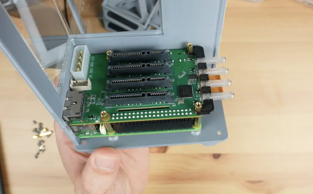
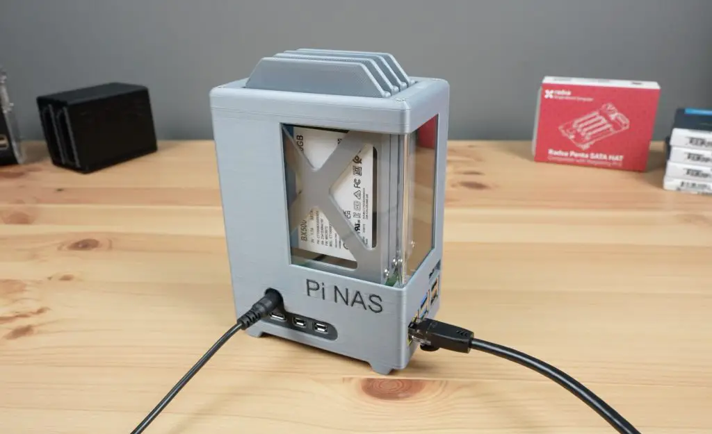
I’m using a Pi 5 with a Pimoroni NVMe hat underneath it.
I’ve got a 1TB Lexar NVMe drive plugged into the hat. You can use a larger or smaller drive, or even a duo hat for two drives if you’d like additional storage capacity.
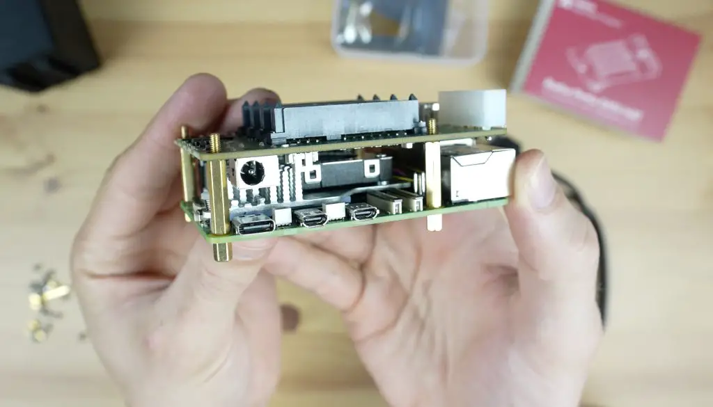
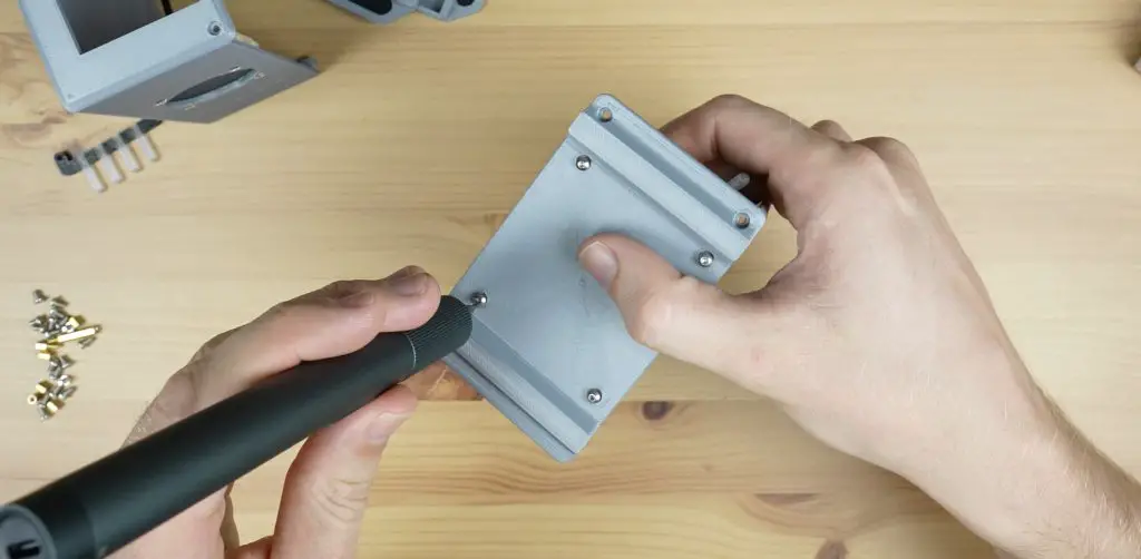
The Pi stack is held in place on some M2.5 brass standoffs that screw into the standoffs supplied with the Pimoroni NVMe base and then some M2.5 button head screws through the bottom of the case hold it in place.
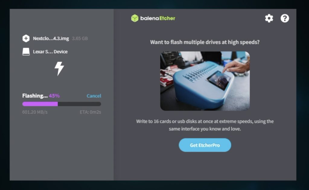
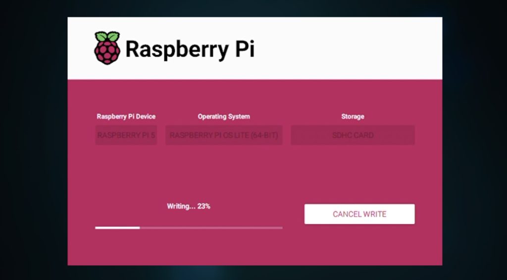
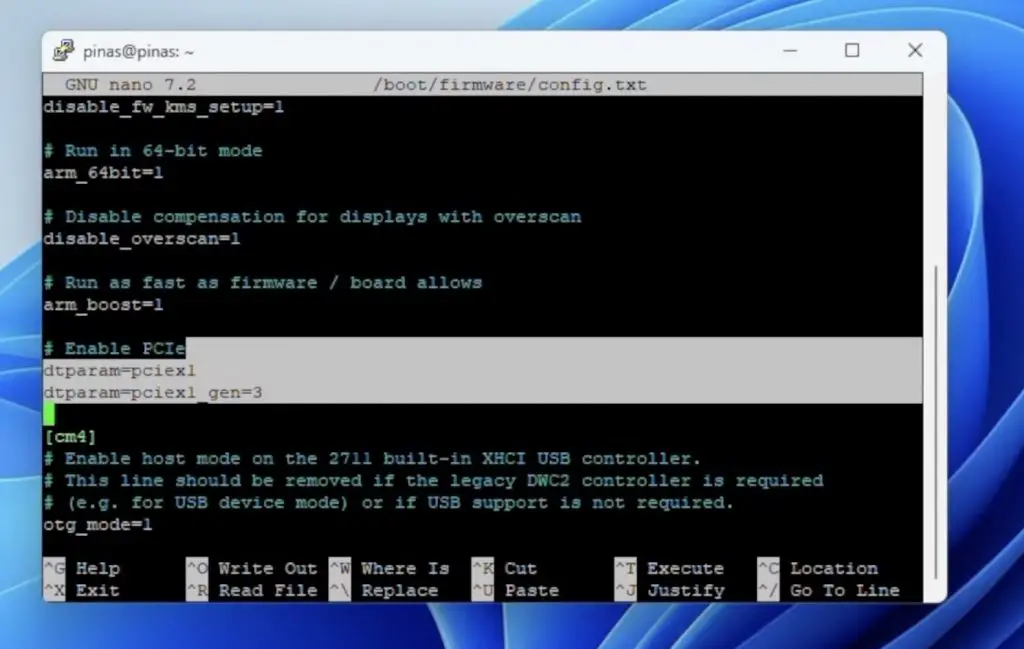
Nextcloud is an open-source software package that takes care of all of the backend work. To install it, we just download the prepared OS image for a Pi 5 from their GitHub repository and then flash it onto our NVMe drive.
We then plug in our network cable and add power to the Pi to boot it up.
Setting Up and Using Nextcloud
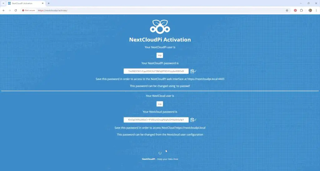
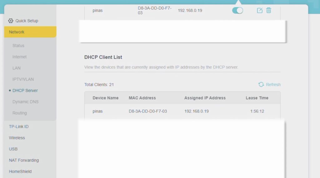
Leave the Pi to run through its first boot and setup process for about 5 minutes and you can then access it by going to https://nextcloudpi or https://nextcloudpi.local on a browser on a computer on the same network as the Pi.
The first time you go to this address you’ll be redirected to an activation page and you’ll need to copy the displayed temporary passwords to log in to your cloud server.
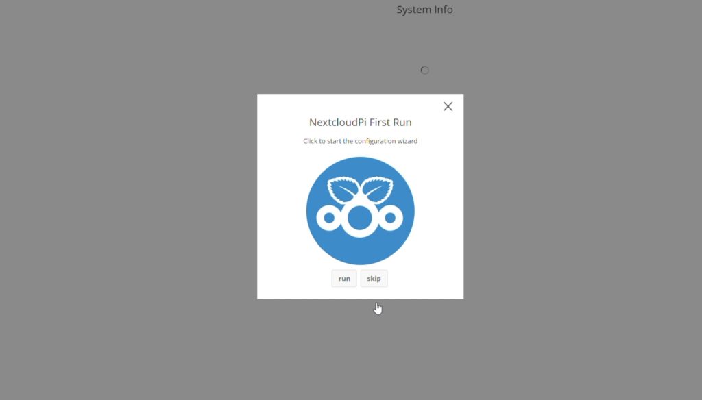
After clicking the Activate button on the bottom of the page, you’ll be prompted to login and then run through a quick setup wizard.
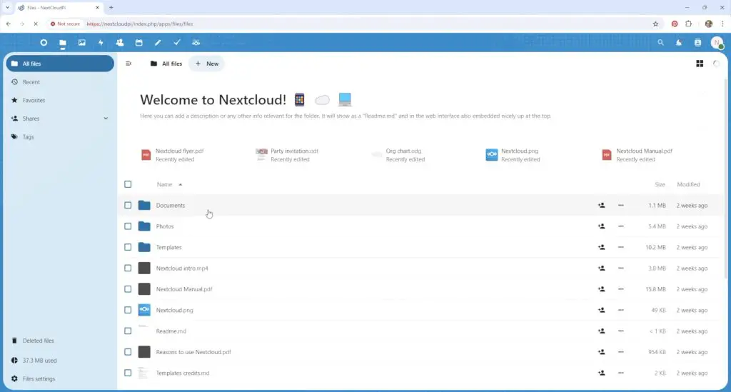
You’ll then land on your Nextcloud dashboard. This looks quite similar to Dropbox, iCloud or Google Drive and is fairly intuitive. You have a root directory which you can add folders to and you can then add and start sharing your files.
Since it’s on your local network and isn’t limited by your internet upload speed, it’s quite fast too. We can copy a 750MB video file to the cloud in under 10 seconds.
We can set up file or folder sharing with other users, similar to other cloud services. It’s also quick and responsive opening up other media like photos.
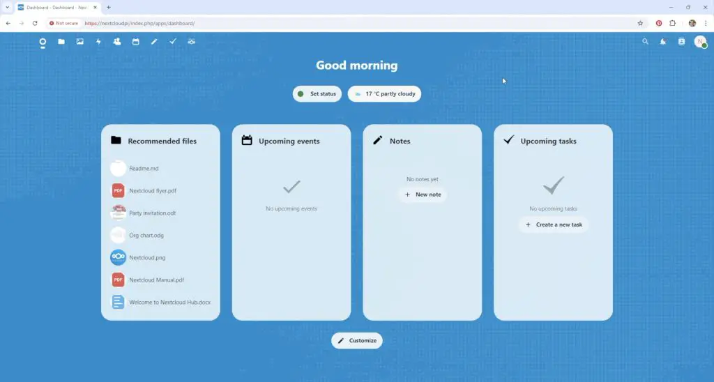
There are a few other features like contacts, a calendar, notes and tasks. So Nextcloud does quite a lot more than just file storage. You can configure how these work and allow them to be shown on your Nextcloud dashboard.
Final Thoughts On The Build and Omtech Polar
And that’s really all there is to it. You’ve now got your own personal cloud storage server running on your home network.
To access your server outside of your home network, you need to set up port forwarding on your router. I’m not going to go into this in this guide as you can open your network up to security issues if you don’t do it correctly, but it is an option so that you’re not limited to using it only within your home.
I’ve currently got mine set up to share documents and photographs with other users on my home network and I have a couple of digital photo frames that make use of the photo library on my server.
Omtech have recently started selling the Polar in Australia, so you can now get free and fast shipping within Australia too. The Polar looks like a well-built machine and Omtech have built up a good brand name, so I’m confident that I’ll be using this laser as my primary one on projects going forward.
I’ve already done some more testing on different materials to get a feel for the correct settings to use.
Let me know what you think of my Nextcloud Pi build and if you have any questions on the Omtech Polar in the comments section below.
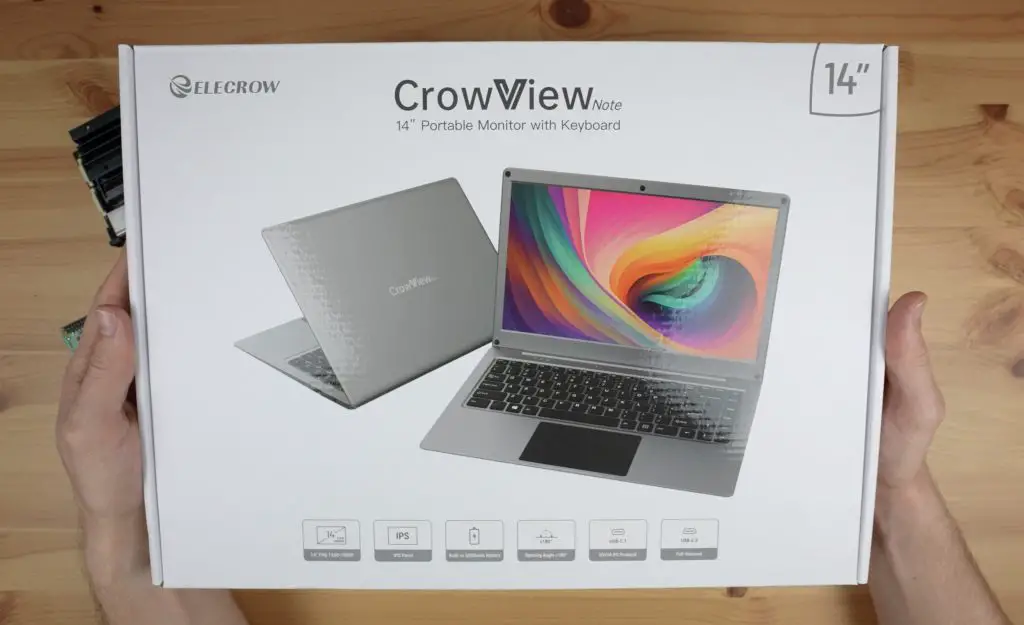
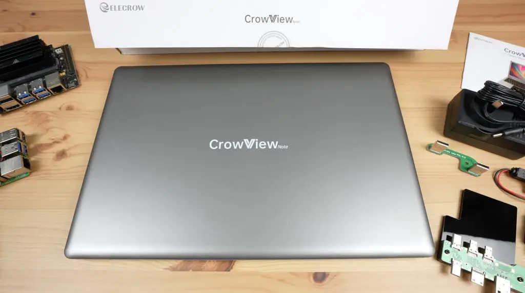
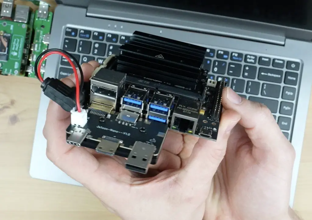
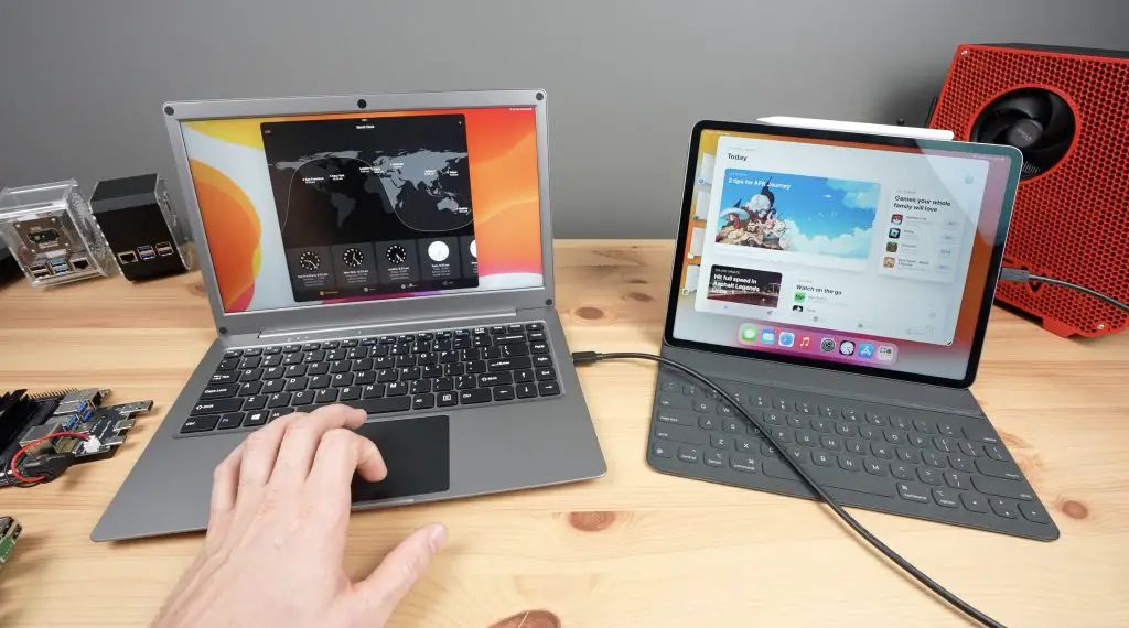
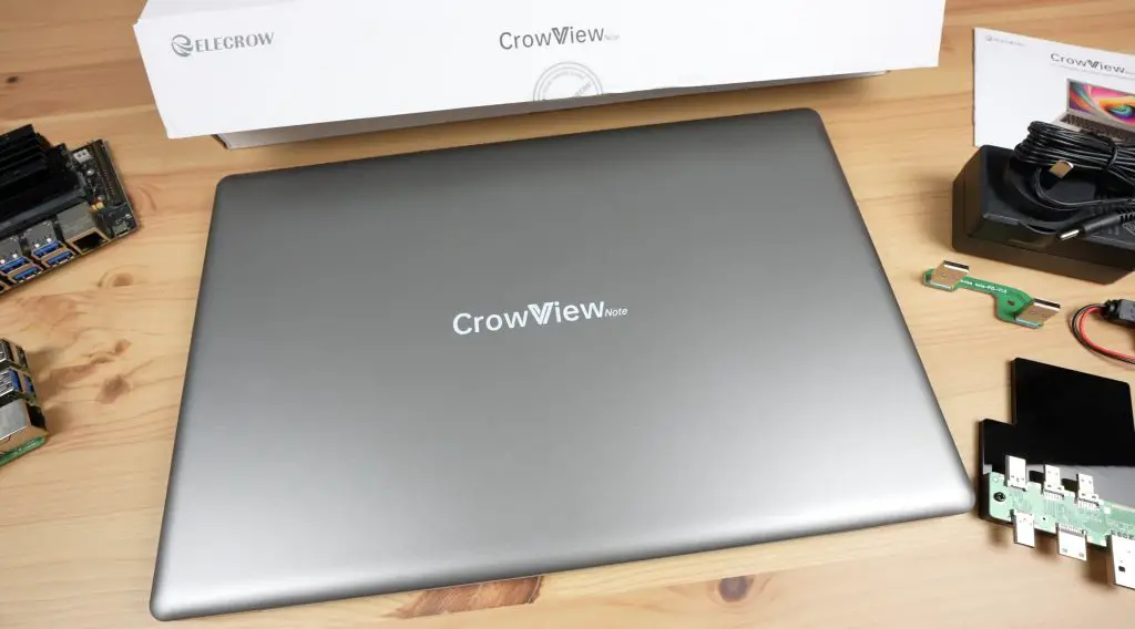
The CrowView Note is a new laptop-style, self-powered portable monitor with a keyboard, trackpad, microphone and speakers built in. It has been designed to be quickly and conveniently connected to a Raspberry Pi, Jetson Nano or other single-board computer or mobile device and can also be used as a terminal for mini PCs or gaming devices.
Let me start off with a quick disclaimer that this is an early prototype that Elecrow sent over for me to try out and share with you. They only launch their crowdfunding campaign later this month, so there may be changes between this and the device that is eventually shipped out.
Here’s my video review of the CrowView Note, read on for the written review;
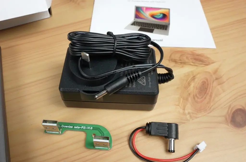
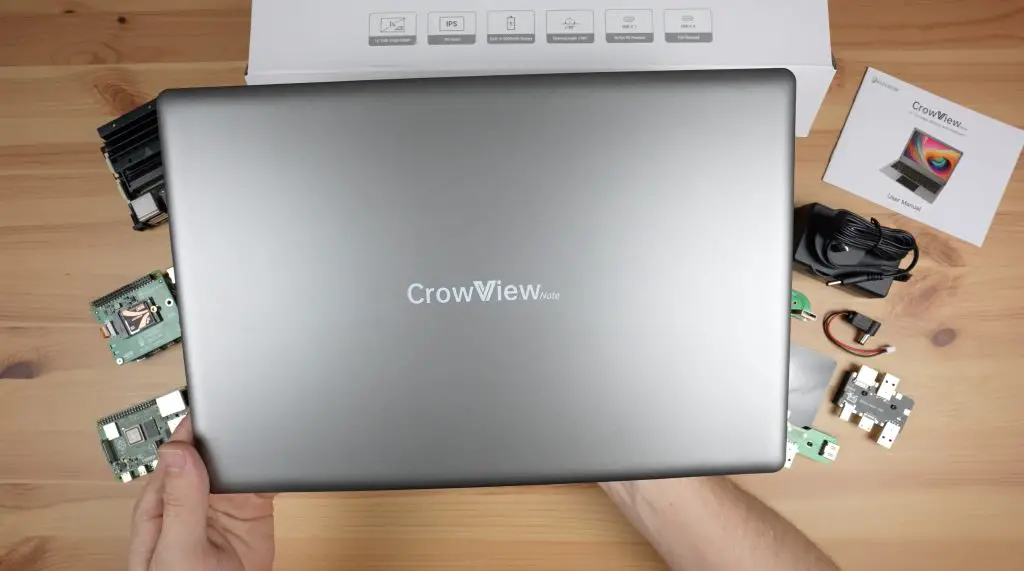
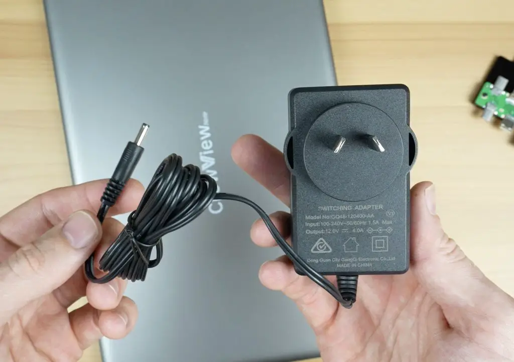
The CrowView Note comes in a white branded box. Inside the box is the CrowView Note, a power adaptor and two adaptor boards, one for a Raspberry Pi 5 and one for an NVIDEA Jetson Nano.
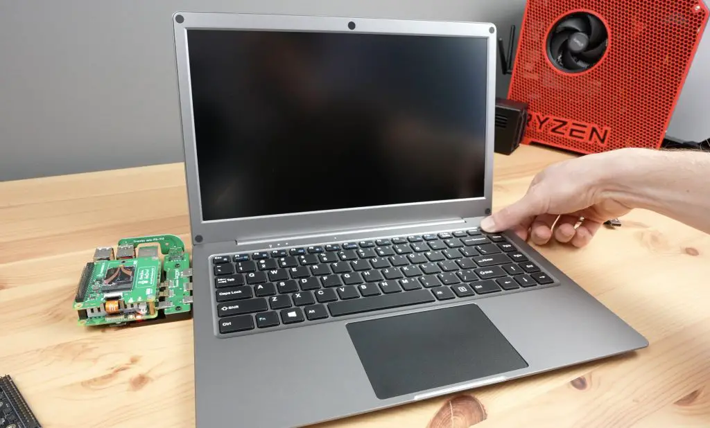
The body of the CrowView Note is plastic, although it is finished to look like aluminium. It would have been great to have an all-metal shell but I presume it’s plastic to keep the cost down.
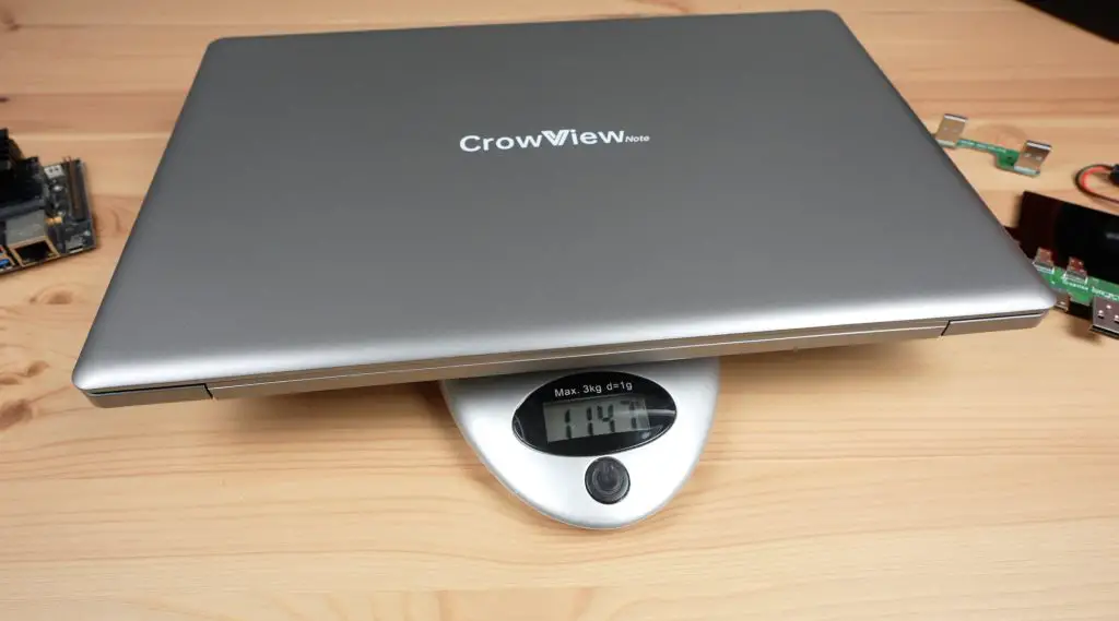
It weighs a little over 1.1kg (2.5lbs) and has a built-in 5000mAh battery. We’ll see what this looks like in terms of battery life in a bit as this will depend on what it is powering.
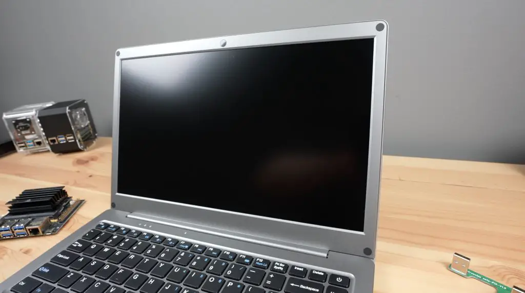
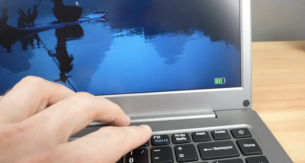
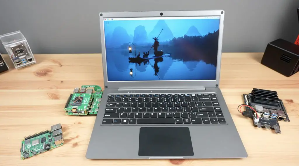
First up, the display is a 14” 1080P IPS panel with a refresh rate of 60Hz.
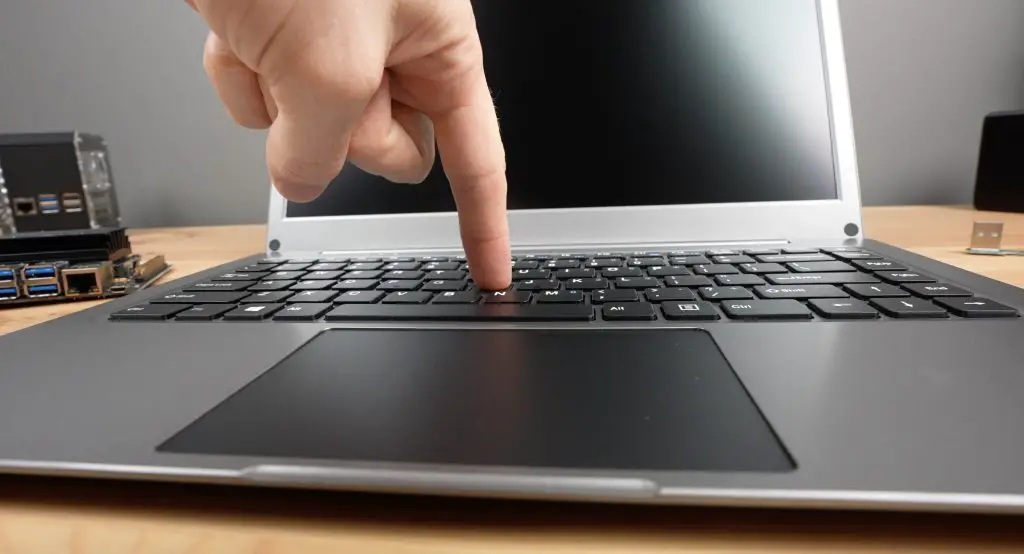
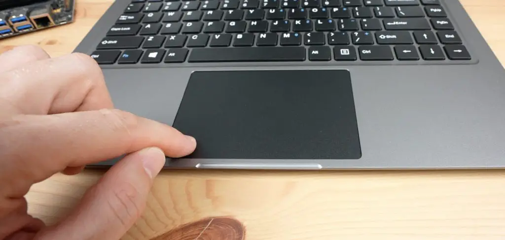
Then we’ve got a keyboard and trackpad. The keyboard feels fairly decent and comfortable to use. The key presses are good. The frame is quite thin so there is a bit of flex if you push down hard on the keys. It doesn’t feel like a high-end keyboard, and it’s similar with the trackpad. You can’t click on the trackpad at any position, the left and right click are only at the front of the pad.
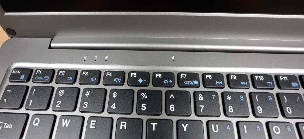
It’s got a range of function keys like most laptop keyboards. These keys control the volume and backlight, turn the trackpad on or off and provide some media controls.
Above the keyboard are some indicator LEDs. We’ve got a status indicator that is on when the CrowView Note is powered on. Then a Capslock and Numlock indicator and a microphone.
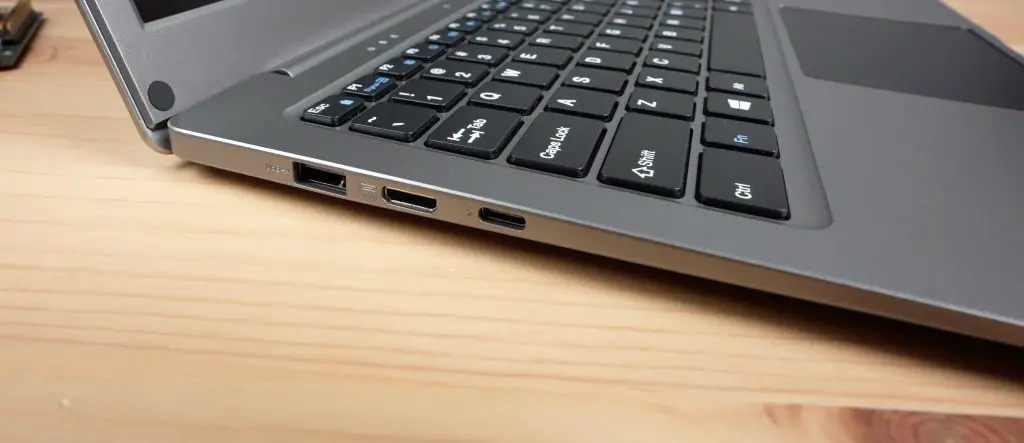
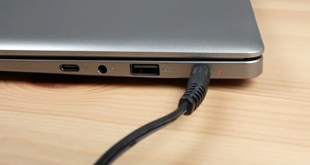
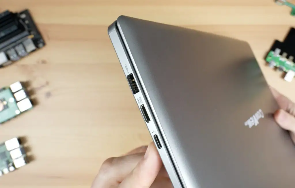
On the left side of the CrowView Note, we’ve got a USB port to connect the keyboard, trackpad and other IO. Then there is a mini HDMI port for the display input and a USB-C port to power the connected device at 5V and up to 5A. This was designed to match the Raspberry Pi 5’s power supply requirements.
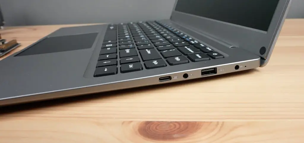
On the right side, we’ve got another USB-C port. This one is full-feature though. So devices that support USB-C DisplayPort can make use of a single USB cable to this port to charge the device and to connect to the CrowView Note’s display, keyboard, trackpad and other features. Next to that is a headphone jack that redirects the speaker audio. Then we’ve got another USB port. This port can be used to add peripherals to the connected device.
Lastly, we’ve got a 3.5mm barrel jack. This is for power, provided by the included 12V, 4A adaptor. It would have been nice to have power supplied through a USB-C port but I’m glad they’ve gone with this rather than a dangerous non-power delivery 12V USB-C power supply that I’ve seen on some other devices.
This little hole next to the power port is an indicator LED that lights up red when the internal battery is charging.
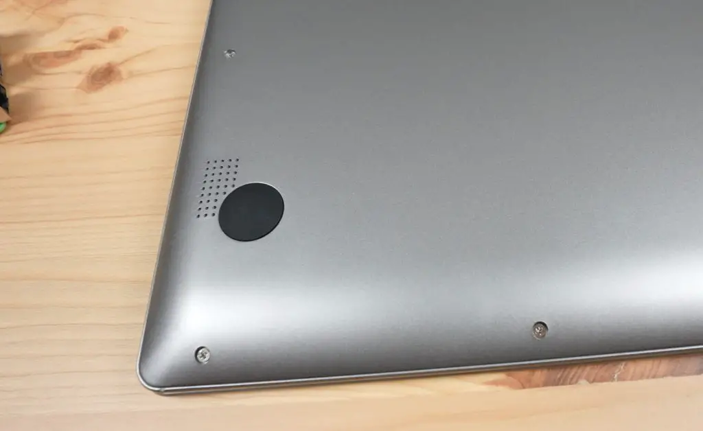
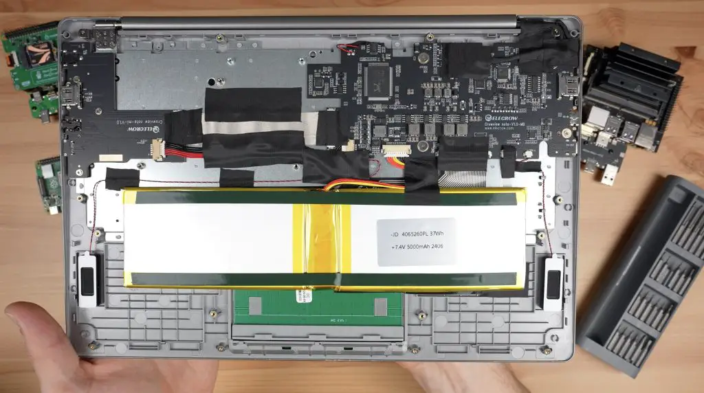
The speakers are underneath the CrowView Note. Their product sticker covers what seems to be an NVMe drive access slot. So, I assume this is a laptop frame from an actual laptop that has been repurposed for this product, again likely to keep costs down.
We’ll open the bottom up later to take a look inside.
So that’s an overview of the hardware, now let’s get a Pi connected to it to try it out.
Connecting A Raspberry Pi 5 To The CrowView Note
Flexibility is what Elecrow had in mind when designing the CrowView Note, so instead of providing a proprietary port through which a carrier board can be connected, they have designed the interfaces through standard ports. This means that you can either use their carrier boards to connect specific devices and remove the need for cables, or you can connect devices without a carrier board by using standard cables.
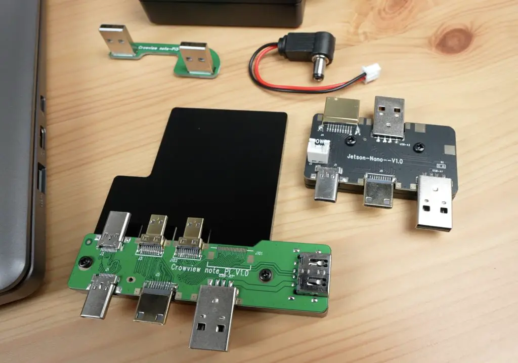
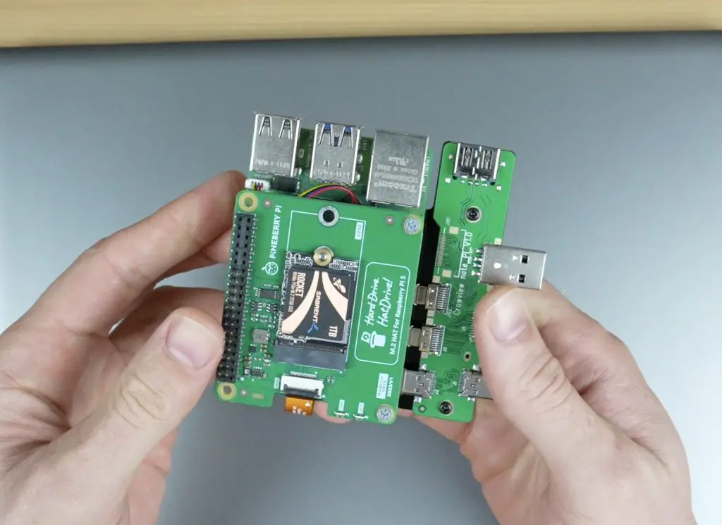
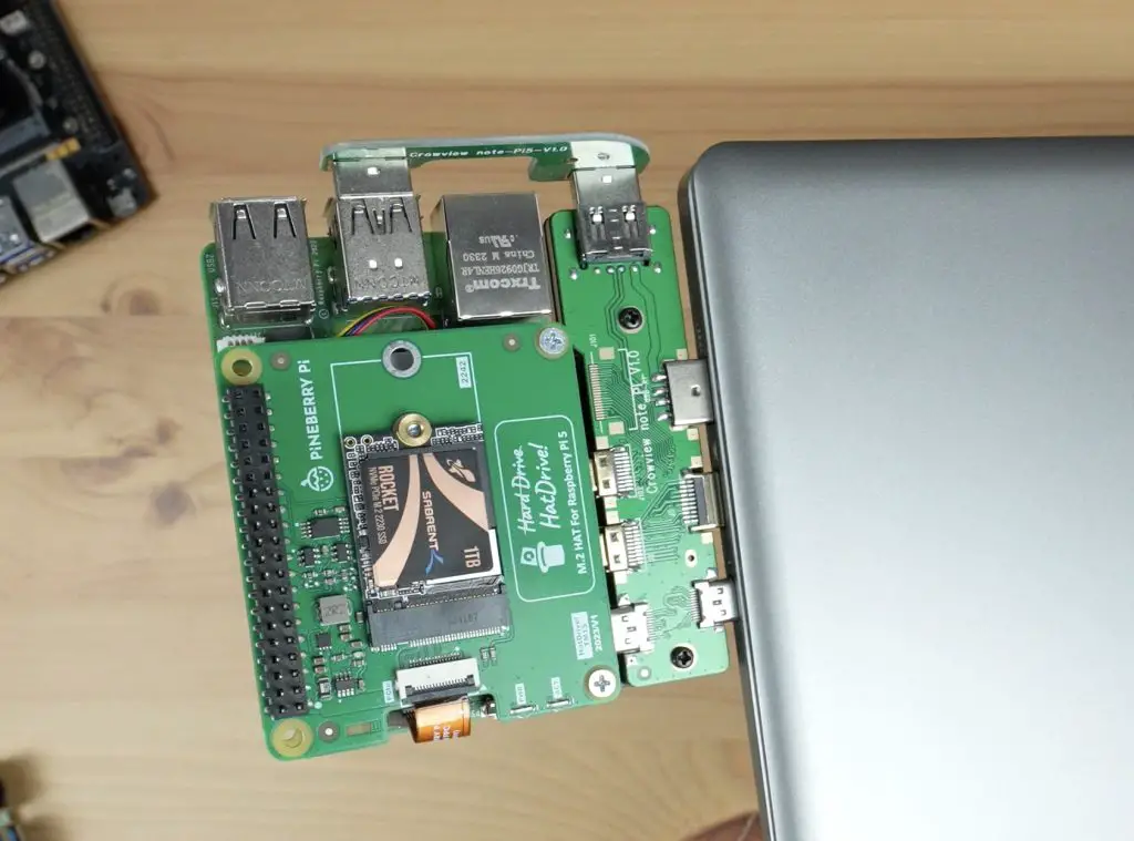
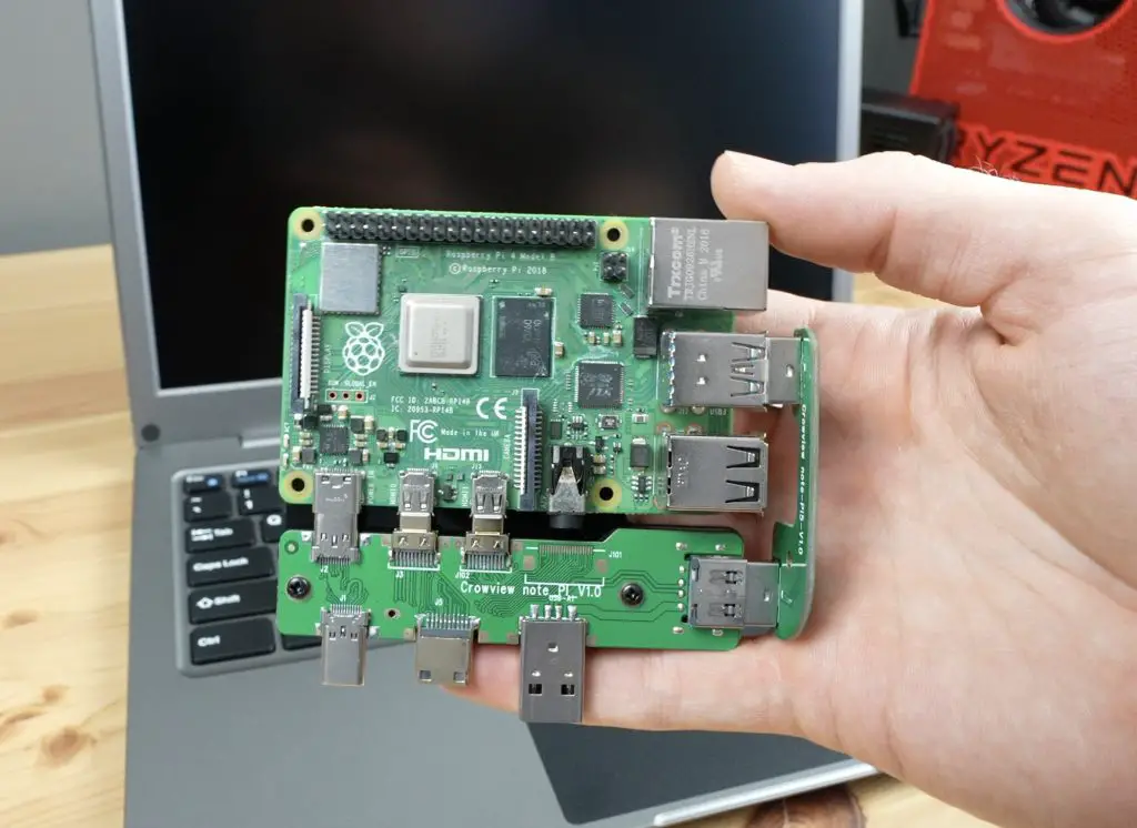
To connect our Pi to the CrowView Note we’re going to use one of the two included carrier boards. We have one for a Pi 5 and one for a Jetson Nano developer kit.
The Pi version connects to the USB-C and HDMI ports on the side of the Pi and then uses a jumper across to one of the USB 3 ports on the front.
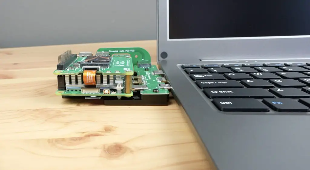
The carrier board then plugs into the three ports on the side of the CrowView Note.
They’ve added acrylic to the bottom of the adaptor board to support the Pi, so it’s not just hanging on the ports. It’s supported by the desk underneath it, even if you press down on it.
I’ve charged the battery overnight so I’m not going to add the power cable at this stage. Let’s see how it goes being powered solely by the internal battery.
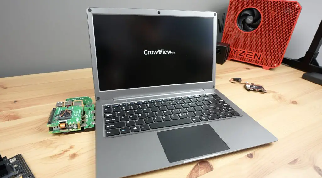
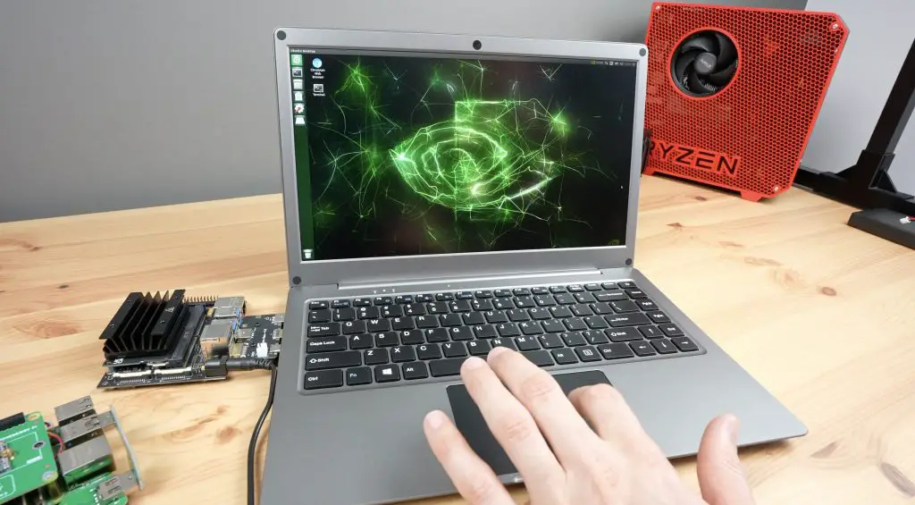
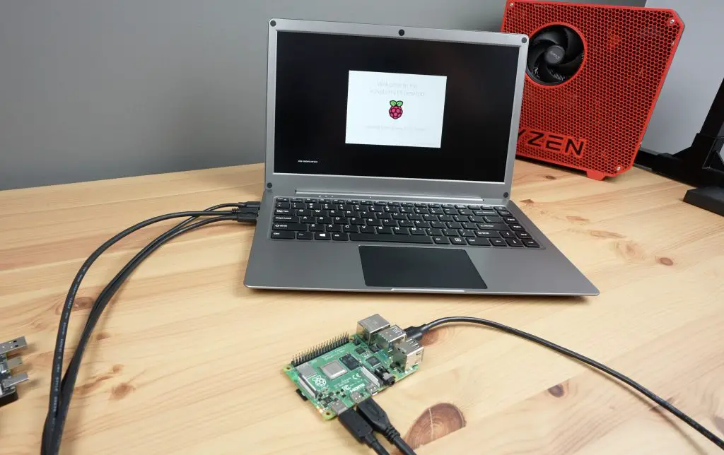
Pressing the power button provides power to the Pi 5 to boot up.
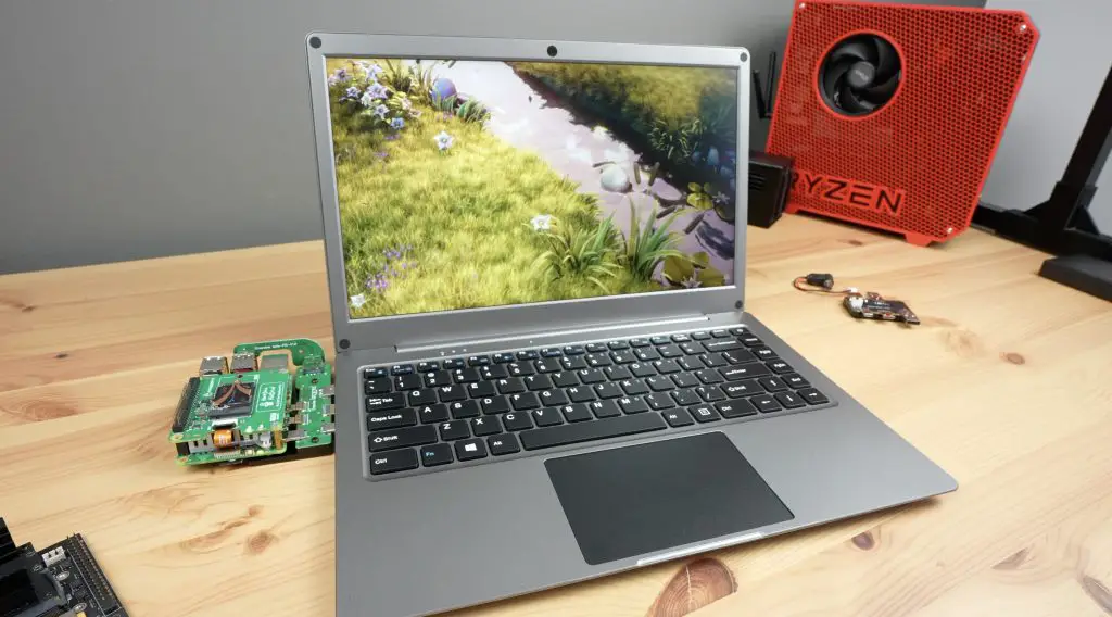
Once booted up we’re on the desktop. The display looks really good. The image quality is great, the colours look accurate and the viewing angle is relatively wide for a laptop-style display.
As I mentioned earlier, we’ve got a number of function keys across the top row. I quite like the battery indicator. Pressing this key pops up with an indicator on the bottom right of the display that shows how full the battery is.
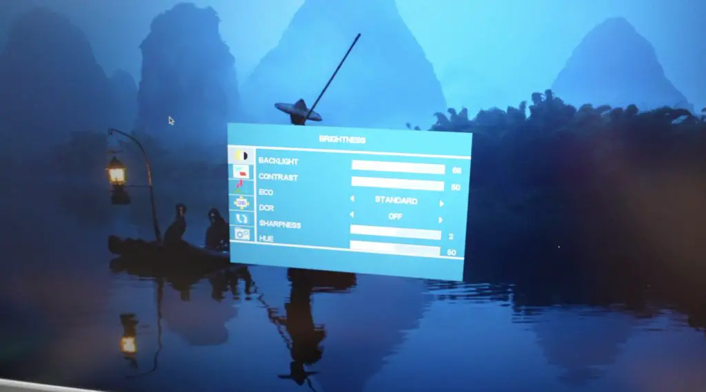
There is also a full menu with display settings like a traditional monitor.
The trackpad is quite good, you’ll need to turn up the pointer speed, but there is no input lag. You can do the usual tap-to-click but can only really physically left or right-click the mouse in the front third.
The stereo speakers are ok, they sound a little tinny at higher audio volumes, but it’s nice to have them included as an option. My video at the beginning of the post has a sample of the audio when watching a video.
The CrowViews power button is not connected to the Pis power button. So you need to shut down the Pi safely by either pressing its power button or doing it through software. You’ll then need to then press the CrowViews power button to remove power to the Pi once shutdown.
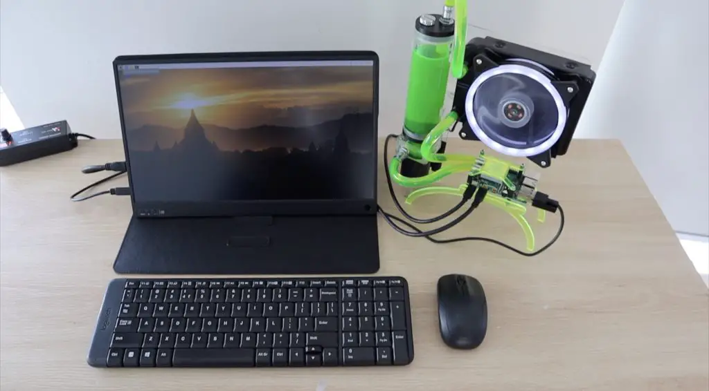
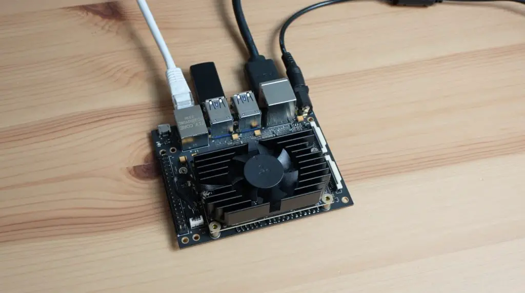
We can also easily connect a Jetson Nano by using the second included carrier board. This is a bit quicker than with the Pi since all of the Jetson Nano’s ports are on one side already and we just have a jumper for power.
My nanos carrier board is unfortunately a 9-19V board so I’m going to have to use external power as the CrowView Note only does 5V.
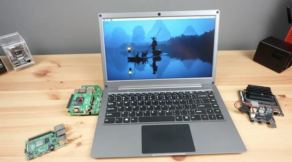
Connecting Other Devices To The CrowView Note
It may seem a bit strange to have the Pi, Jetson or other computer outside of the laptop-style shell. Elecrow have made a Laptop-style computer for a Raspberry Pi previously which integrated it into the enclosure. This results in a very thick laptop base which reduces portability and access to the Pi, so I prefer this arrangement. This design also allows you much more versatility to use different single-board computers, mini-computers and mobile phones, all with minimal effort.
The adaptor board for the Pi 5 will also work on the Pi 4 if you want to connect one of those.
Or, as I mentioned earlier, you can also connect any single-board computer up using standard cables instead of the adaptor board.
If you’ve got devices like a mobile phone or tablet that supports a USB-C attached display, then a single cable provides another display and connects the peripherals.
Battery Life On The CrowView Note
In terms of battery life. I got about 2.5 hours when running the Pi 5 with an NVMe drive and a moderate load. You’d probably get close to 3.5 hours on a light load or idle on the desktop. The CrowView Note won’t safely shut down the Pi when the battery is empty, so you’ll need to keep an eye on it.
They made the USB-C power port specifically to match the requirements of the Pi 5 but it would have been nice to have power delivery available for a variety of voltages. This would provide support for more power-hungry devices and fast charging charging, so you could use the built-in battery as a sort of power bank.
Inside the CrowView we can see the battery, which is a 7.4V battery, so that gives us 37Wh. It would have been great if they increased the capacity of the built-in battery to take advantage of all of the space in the enclosure.
Final Thoughts On The CrowView Note
I think the CrowView note is perfect for someone who does a lot of travelling or works on a range of single-board computers fairly often as I do. It’s obviously not for everyone and isn’t going to suit someone who wants to use it as a traditional laptop-style computer. If you’re not making use of the ability to swap out the connected device often then this probably isn’t for you.
I’ve used this setup with a portable monitor and wireless mouse and keyboard quite a lot in the past and I think the CrowView Note would fit right in as an all-in-one replacement for it.
It would also be great to see a wider range of adaptor boards be made available for different SBCs. I would be interested in one for Pi Zero 2 W.
A big part of whether this is going to do well or not is going to hinge on the pricing. It’s going to be competing against someone buying similar spec. hardware individually, so its price needs to be competitive with that. I’d say somewhere around $150 would be good value for money, but we’ll have to wait and see what they launch at.
This product is still in the Crowdfunding stage, which obviously comes with some inherent risks. Use your own discretion when supporting these types of projects. Elecrow have been around for several years and have successfully crowdfunded 5 other products, so they’ve been reliable so far.
Let me know what you think of the CrowView Note in the comments section below. What can you see yourself using it for?
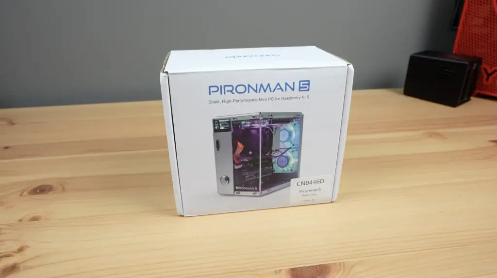
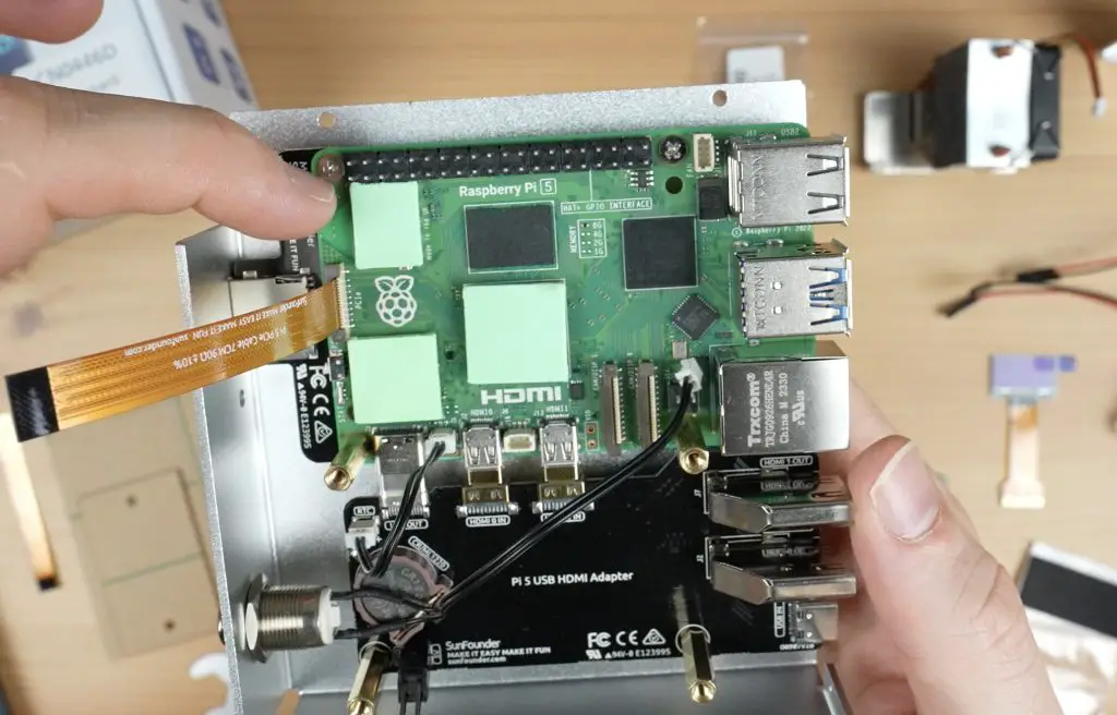
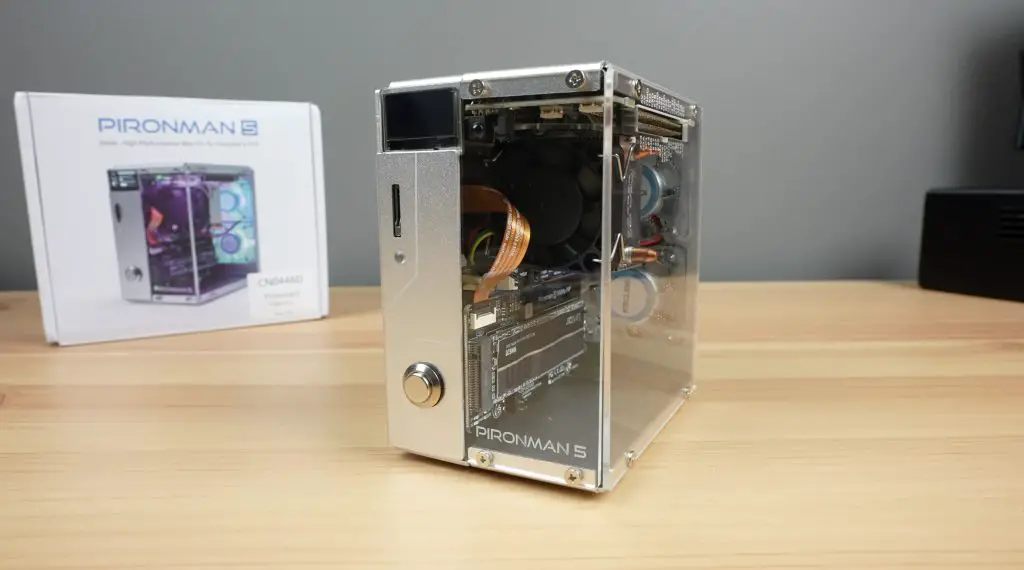
Today we’re going to be taking a look at new the Pironman 5 case by Sunfounder. This case has been designed to house a Raspberry Pi 5 along with an NVMe storage drive.
It’ll set you back almost $80, but it has quite a lot to offer. So let’s see how easy it is to put together, how the Pi and NVMe drive perform in it and whether it’s worth the money.
This is the second generation of Pironman case, although it doesn’t look all that similar to the first. The first generation was made for the Pi 4, which didn’t have a PCIe port. This case takes advantage of the port to add an NVMe drive to the Pi without the need for an external USB jumper. They’ve also shifted from a two-opposite clear side panel design to a wrap-around clear panel design.
Here’s my unboxing and review video, read on for the write-up;
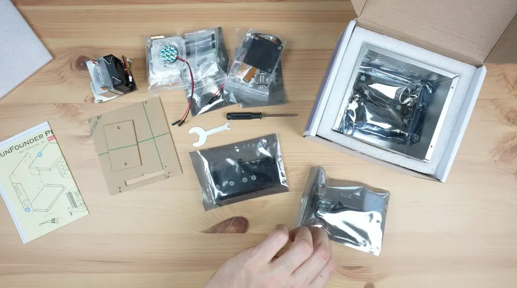
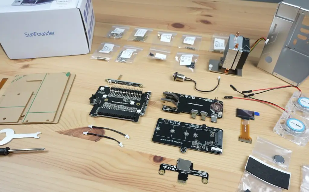
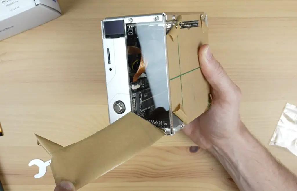
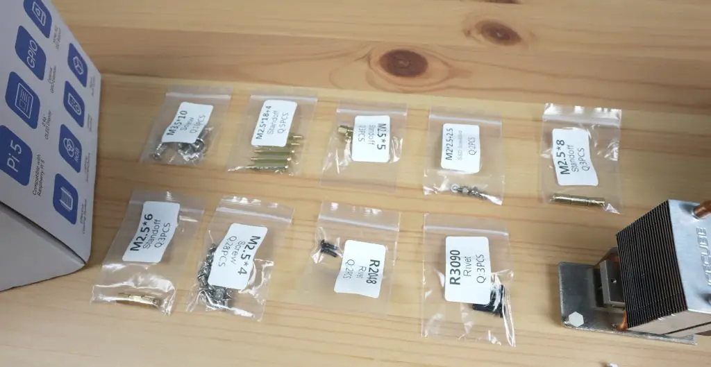
The case comes in a fairly large white branded box. Inside it is the aluminium case shell packed full of the case components, including fans, cooler, expansion boards and mounting hardware.
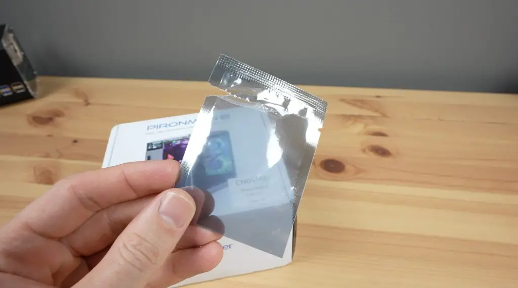
Oddly, I did get a random open and empty sleeve in mine. I don’t know if that means something is missing or if it just found its way into the box but I guess I’ll find out when assembling it.
You can see from the spread that there are a lot of components to this case. Like with the previous Pironman case, it’s going to take more than a couple of minutes to put it together.
Assembling The Pironman 5 Case
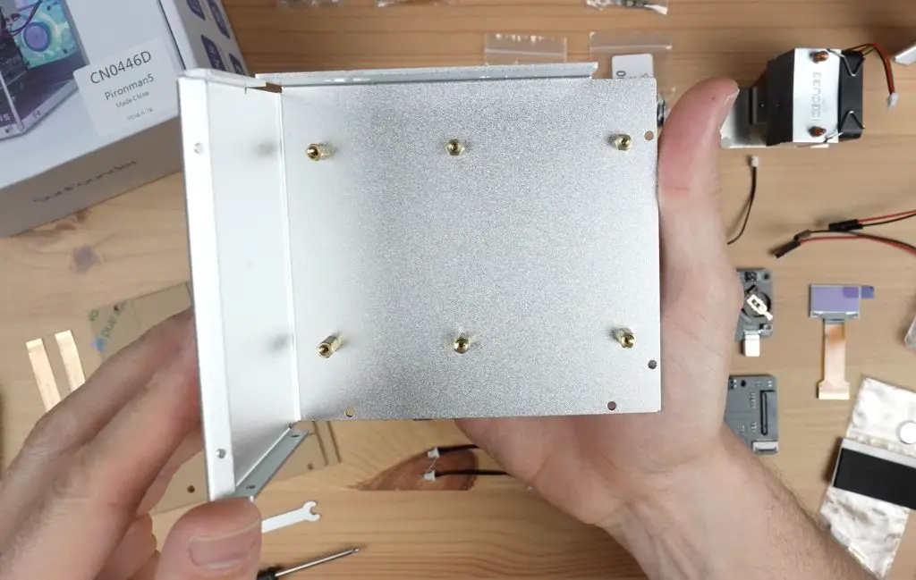
To assemble the case, you start by adding standoffs to one enclosure half.
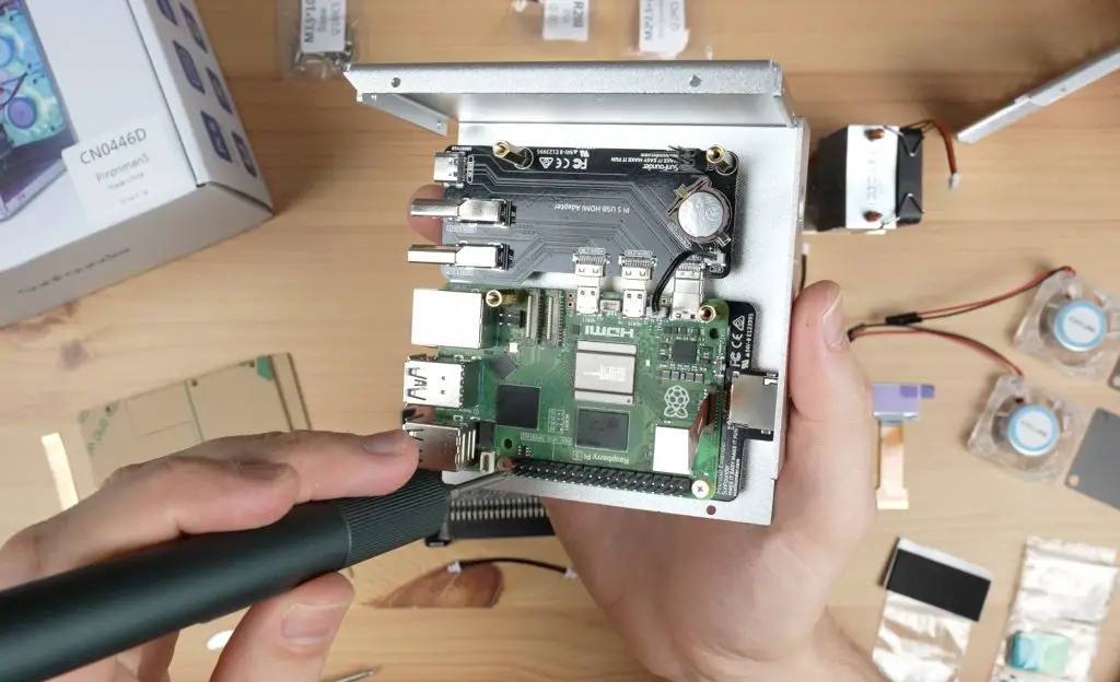
You then plug some of the carrier boards into the Pi, then mount the assembly into the case.
The power button and cooler go in next. They supply pads for the WiFi chip and power circuitry which is a bit different. Previously this cooler covered the RAM chips, USB and Ethernet controller.
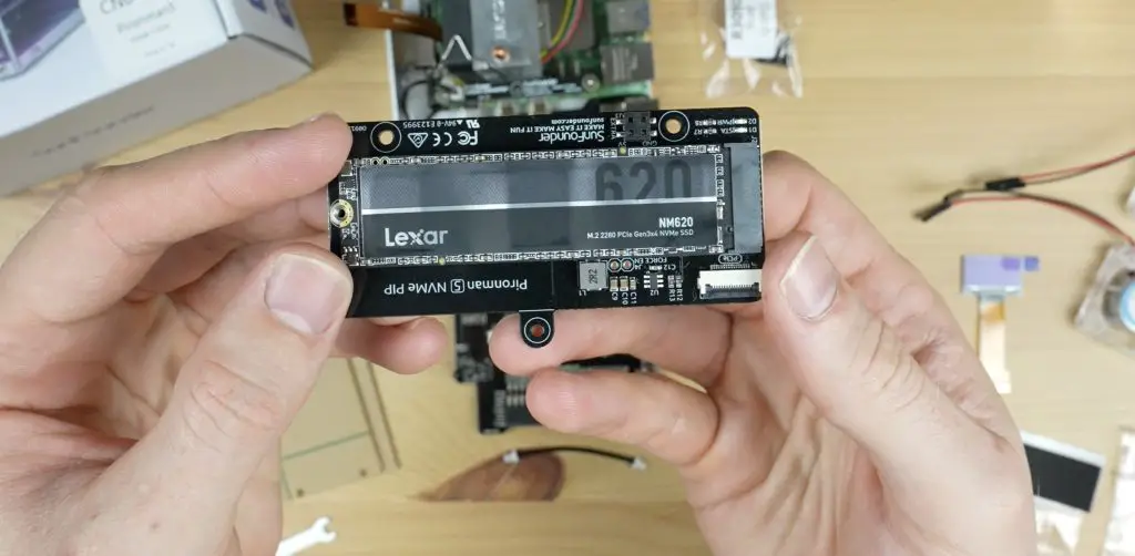
Next, we install the NVMe drive.
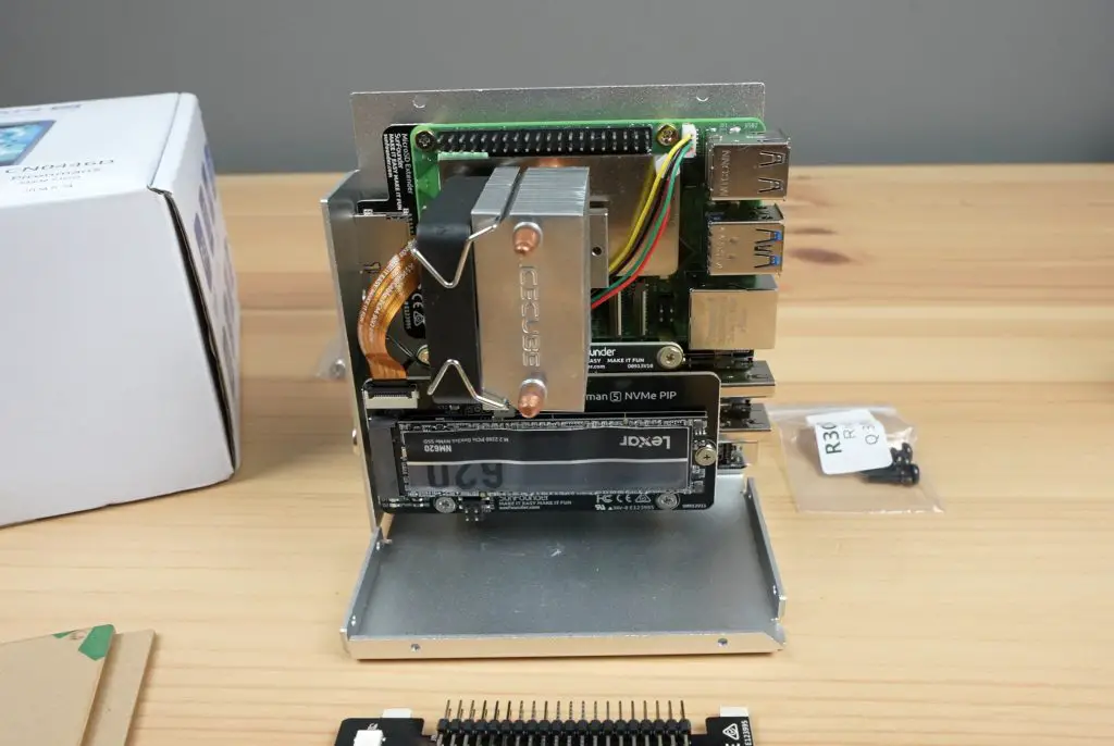
The NVMe drive carrier board supports multiple drive sizes from 2230 to 2280. I’m going to be using a 2280-size Lexar drive in the case. This is not all that fast as far as NVMe drives go, but it runs at gen-3 speeds, so it should get quite close to the maximum speed that the Pi can handle.
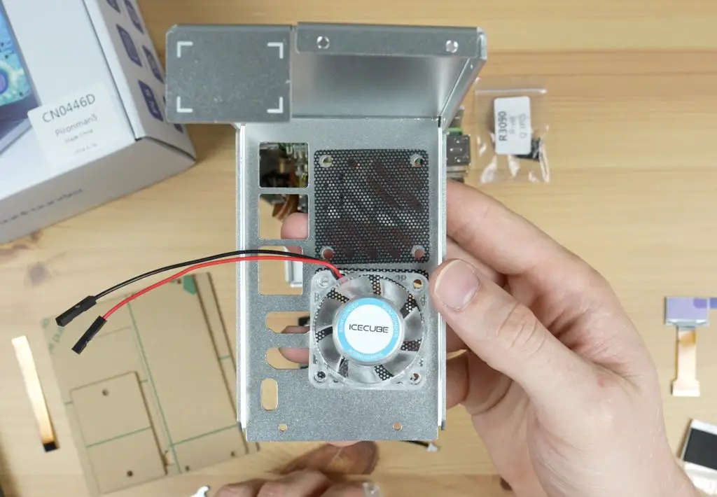
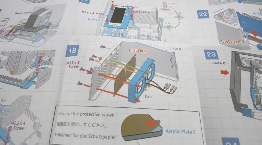
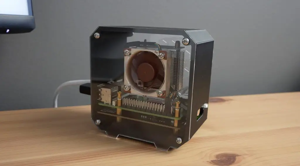
We then attach the fans to the back panel.
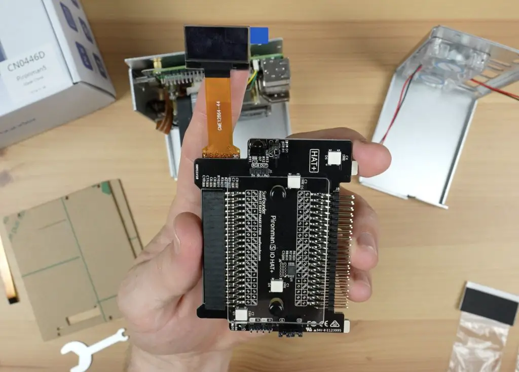
With that done, we can mount the GPIO expansion board with the OLED display.
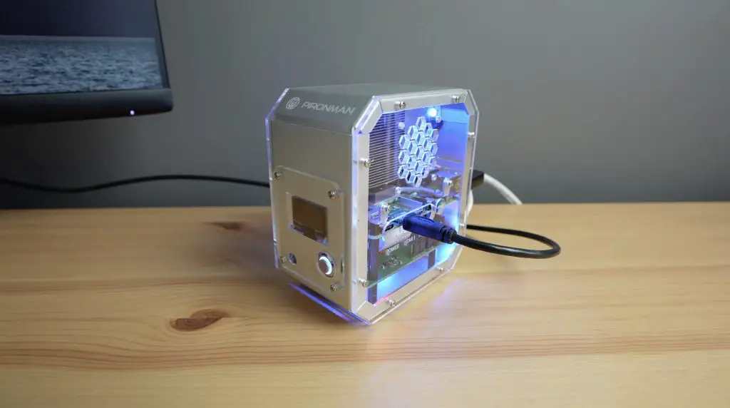
Then screw the two aluminium case halves together and stick the display onto the front panel.
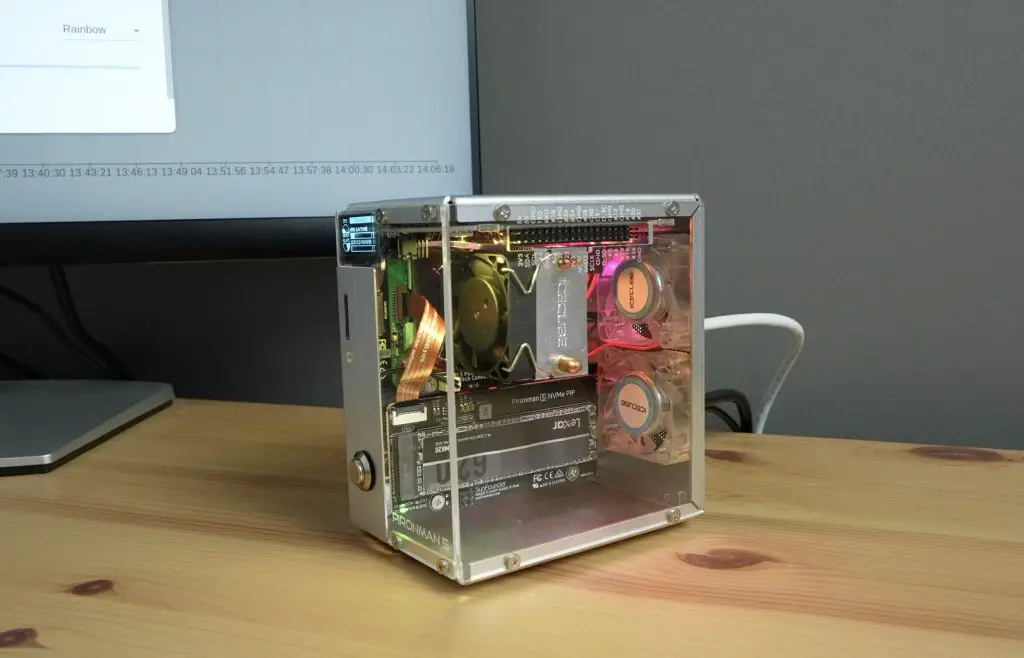
To finish it off, we add the clear acrylic panels.
Assembly is relatively easy. The case comes with a good step-by-step illustrated instruction sheet and the hardware is labelled well too. It took me about 30 minutes to have the case complete and ready to boot up.
Pironman 5 Software and Web Dashboard
Booting up the Pi is done by pressing the power button on the front of the case.
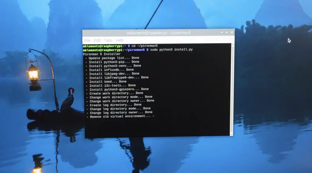
To get the display and lighting to work, we need to install some additional software. This is a fairly simple GitHub install by entering the following commands in the terminal:
cd ~
git clone https://github.com/sunfounder/pironman5.git
cd ~/pironman5
sudo python3 install.py
The script took about a minute to install and I didn’t run into any issues with it.
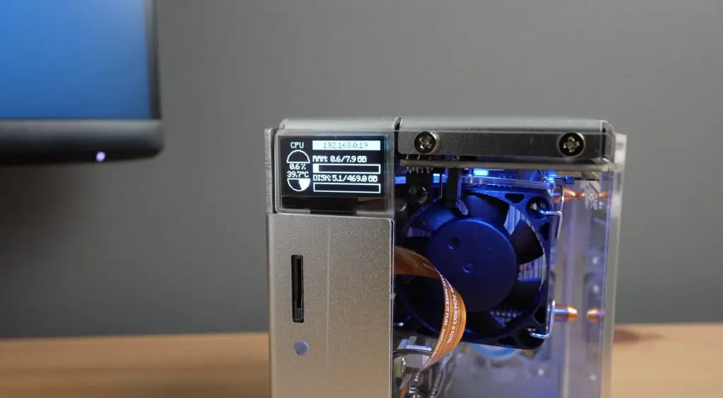
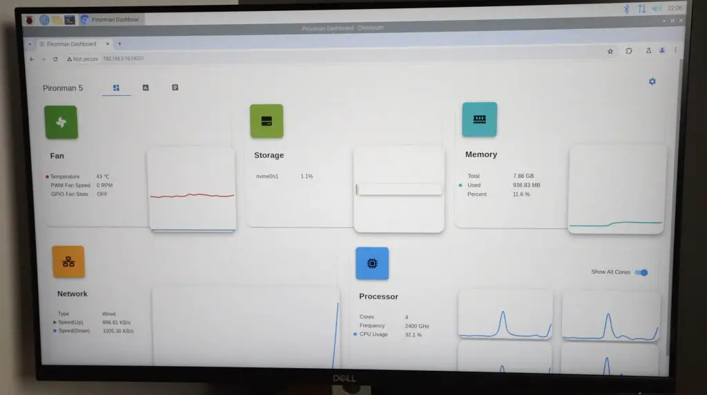
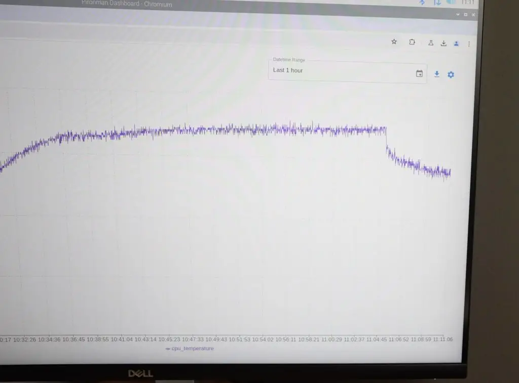
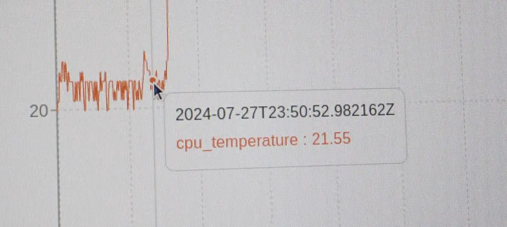
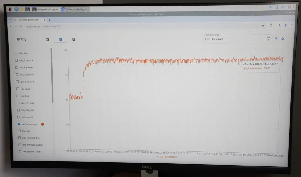
The fans turn off and the OLED display comes on when the installation completes, but it still recommends a reboot. The OLED display on the front shows the CPU usage and temperature, the computer’s IP address as well as the RAM and storage capacity.
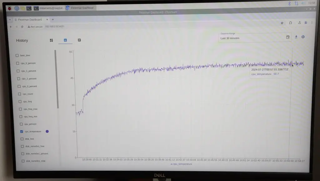
Their software also has a really nice web dashboard, accessible by entering the IP address and port 34001 into the browser.
http://<ip>:34001
This dashboard allows you to see your system stats, plot graphs of the stats, see logs and access some of the case script settings.
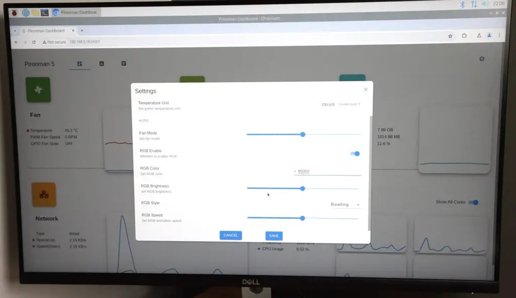
You can also change the style and colour of the RGB lighting, adjust its pulse mode or set it to cycle through different colours.
Testing The Case’s Cooling Performance
One of Sunfounder’s claims about the case is superior cooling. I personally use one of these tower-style coolers on my Pi 4s and 5s running in my 3D-printed cases. So I’ll use that as a baseline and see if the additional fans and this slightly different cooler base make any difference to the thermals.
I’m also interested to see how loud the case is when it is running as we’ve got three 40mm fans in it. The back two are not PWM fans, so they’re either on at full speed or they’re off. The default setting is for them to turn on when the CPU reaches 60°C, but this can be adjusted.
I’m going to adjust them to have the back two fans running at full speed for the stress test to see how it compares to my case’s thermals.
My case has a single 40mm PWM fan and I’ll set this to 100% for the comparison as well.
I’m going to be using CPU Burn to apply full load to the CPU and we’ll leave that running to see what temperature it stabilises at. I doubt we’ll get anywhere near thermal throttling with this cooling setup.
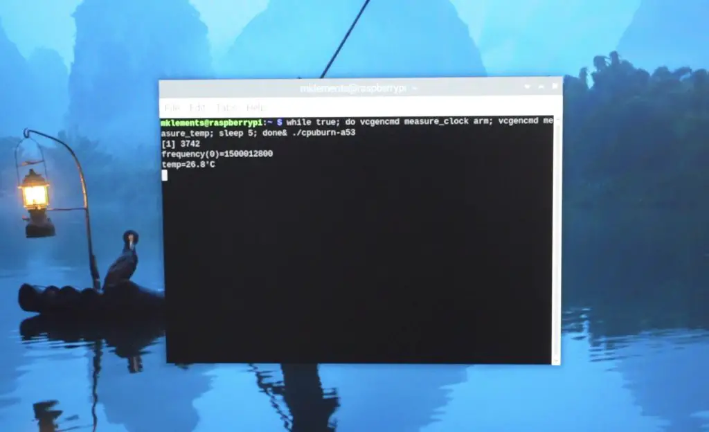
To install CPU Burn, we enter the following command into the terminal;
Then to run the test, we enter the following command;
while true; do vcgencmd measure_clock arm; vcgencmd measure_temp; sleep 5; done& ./cpuburn-a53
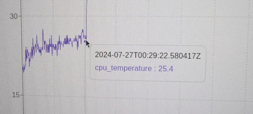
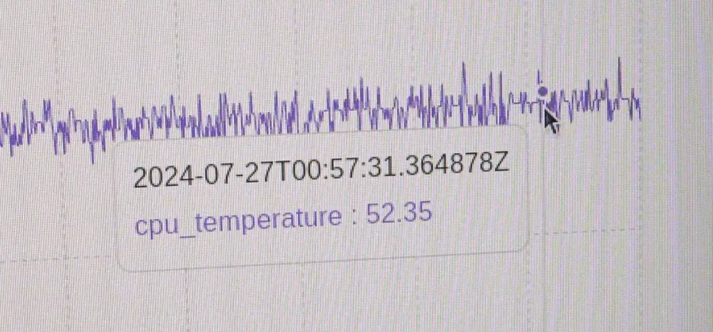
At the stock CPU frequency of 2.4GHz, at idle, the CPU temperature started at 25°C. I left the test running for a little under 30 minutes and it stabilised at 52°C. So we’ve got a delta of about 27°C, which is really good. This means you’ve got a lot of headroom for overclocking.
The fans are not as noisy as expected, but they would be annoying if you had this on a desk next to you and they were running the whole time. I’ve put an audio clip of them running into my video at the beginning of the post. Thankfully, having them only turn on at 60°C means that they’re off most of the time and only come on when you put a demanding load on the Pi.
With the fans still on, the Pi’s CPU drops back down by 10°C in about 5 minutes.
I ran the same test on my case. This time the starting temperature was 22°C, so 3°C below the Pironman case. The temperature reached equilibrium much faster but I left it running for 30 minutes too. It stabilised at 36°C. So we had a delta of about 14°C, which is significantly better than on the Pironman 5 case.
I think this is mainly down to the airflow path. My case design has airflow straight across the cooler and out some large ventilation holes on the opposite side.
The Pironman case doesn’t really have air inlet vents and the fans at the back are each pushing air through a restrictive dust filter. So although it’s got two more fans than my setup, they aren’t working as effectively.
Testing The NVMe Drive Speed
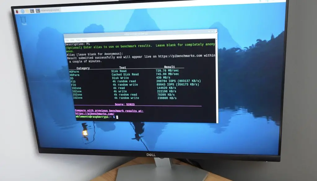
To test the NVMe drive speed, I’m using James Chambers Pi Benchmarks script. This script favours random read-write performance, so is a good representation of how an OS would be using the drive.
To install and run the test, we enter the below command into the terminal;
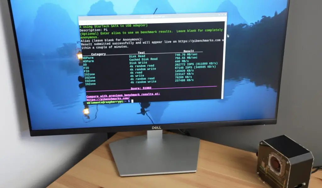
Over 3 consecutive tests, I got an average score of 51,963.
This is a similar score to what I got using the Piromoni NVMe base with this drive on my setup, I got 51,902 and an average of 51,865. So that’s a good indication that there are no issues with the drive adaptor.
It is quite a bit slower than the speeds I got in my recent NVMe hat comparison, but that was done with a Sabrent Rocket drive which is much faster than the Lexar drive I’m currently using.
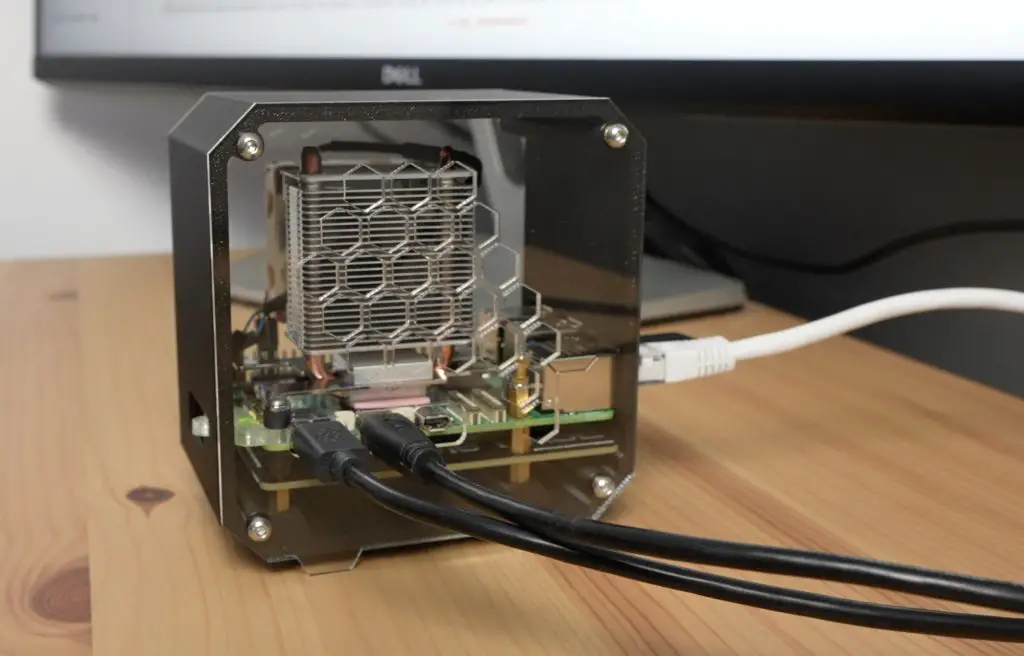
Final Thoughts On The Pironman 5 Case
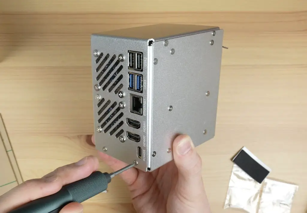
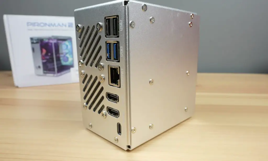
Overall I think the case looks great and provides some nice functionality over the stock Pi. I particularly like the full-size HDMI ports over the stock micro HDMI ports and the fact that the cables run out the back of the case rather than on the back and side.
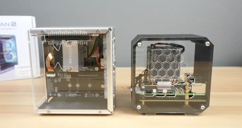
There are also a few good improvements on the original design, assembly is quite a bit easier and it doesn’t rely on the side panels to hold the metal case components in place. So you can have the side panel removed to work on the Pi without compromising on the case’s structural integrity.
In terms of size, it is slightly larger than my 3D-printed case. It measures 112 x 117 mm and is 79mm wide, but they’ve managed to cram a lot of features into the small space.
It’s obvious that Sunfounder have tried to make this the best case for a Raspberry Pi 5. It comes with quite a high price tag, but in terms of value for money, it is fairly good. You can pick this up and you don’t need to worry about getting a separate cooler, NVMe hat, fans or an OLED display, and you still have access to the core Pi’s functionality like its GPIO pins.
It also comes with some nice finishing touches, like labels for the ports, and includes plenty of additional screws and mounting hardware so you’re covered if you lose some of them.
I never found anything missing from the case hardware so I assume that the empty sleeve I found made its way into the package by accident.
If I had to pick out some things to be critical about, I probably would have made the back fans PWM controllable as well. They would then run a bit quieter, although being able to turn them off most of the time in software partially helps with this already.
The dust filters on the back fans are also unnecessary as these are exhaust fans, so you’re filtering dust out that would be leaving the case. These would be better positioned onto some inlet vents and doing so would improve airflow through the exhaust vents.
Let me know what you think of the Pironman 5 case in the comments section below.
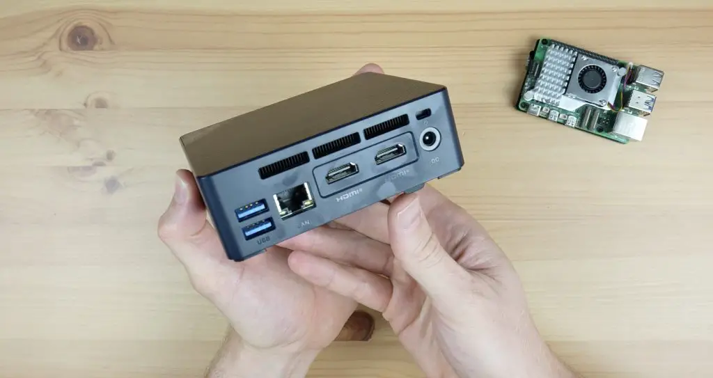
Beelink got my attention two weeks ago when they reached out about a new mini PC that they were about to launch, the GTi 14 Ultra, which has a built-in full-size PCIe gen 4 x8 slot.
One of the biggest weaknesses in these mini PCs is graphics performance. They typically rely on an integrated GPU, and while some have reasonably powerful integrated graphics, they don’t come close to having a dedicated GPU.
I recently showed a way to get around this by taping into an M.2 port on a PC with an Oculink adaptor. This worked fairly well but was limited by the single PCIe lane and looked like a bit of a hack job. Even in a custom 3D-printed case. So I’m super excited to try out this new PC with a fully accessible PCI slot built in.
Here’s my video review of the GTi 14 Ultra, read on for my written review;
The GTi 14 Ultra comes in a white Beelink branded box with minimal text on it. Let’s get it unboxed and see what is included.
There are two versions of this PC that are going to be available. This is the less powerful Intel Core Ultra 7 version and it also comes in an Intel Core Ultra 9 version.
Removing the lid, we’ve got the GTi 14. It’s aluminium housing is protected by a matt plastic film.
Underneath the computer, we’ve got two cables. It looks like it’s got the power supply integrated into the PC enclosure, since we’re only provided with a power lead. This is a bit different to typical Mini PC designs which usually relay on a 19V laptop-style power supply to power them.
So included in the box is the mini PC, a power cable, an HDMI cable and a short user manual.
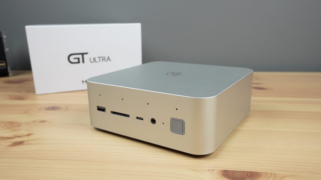
The GTi 14 Ultra is a fair bit larger than most mini PCs I’ve tried previously, but that’s due to the integrated power supply, the full size PCIe port and the need for better cooling on the more powerful CPU.
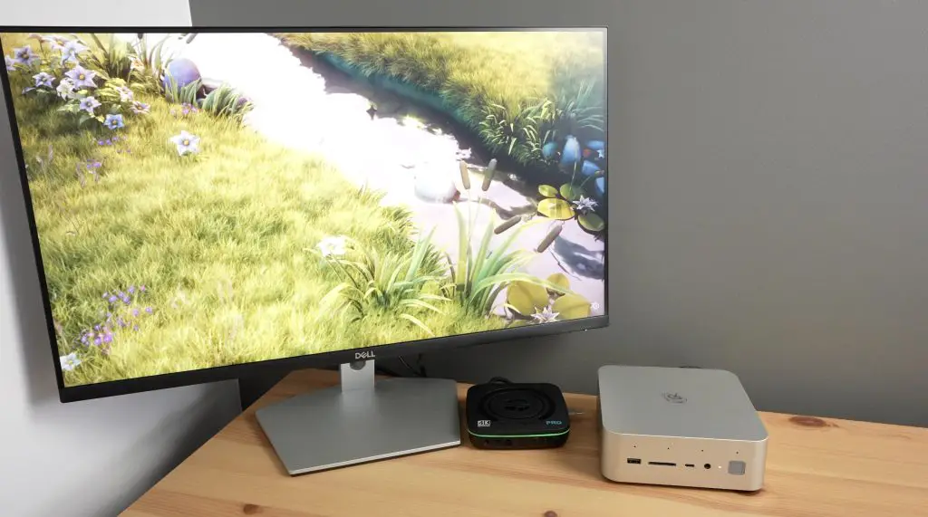
You definitely get Mac Mini vibes from it.
Another thing worth mentioning is that this mini PC doesn’t come with a VESA mount to mount it onto the back of a monitor. It’s designed to be placed onto a desk.
GTi 14 Ultra’s Specifications and Interfaces
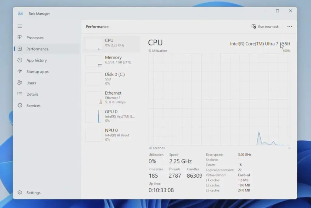
The GTi 14 has an Intel Ultra 7 155H Processor, which is essentially a CPU, GPU and NPU all on a single chip. This is a mobile processor with 24MB of cache and 16 processor cores. It’s got 6 performance cores that can run at up to 4.8Ghz and 8 efficiency cores that can run at up to 3.8Ghz.
It has an integrated Intel Arc GPU with a maximum frequency of 2.25GHz and this supports hardware-based ray tracing, so we should be able to run some games on it to try that out.
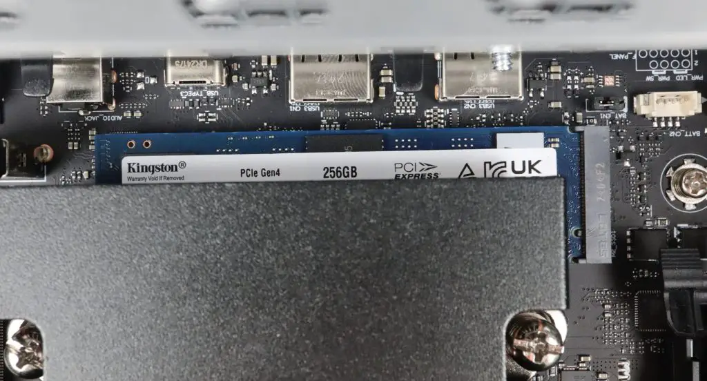
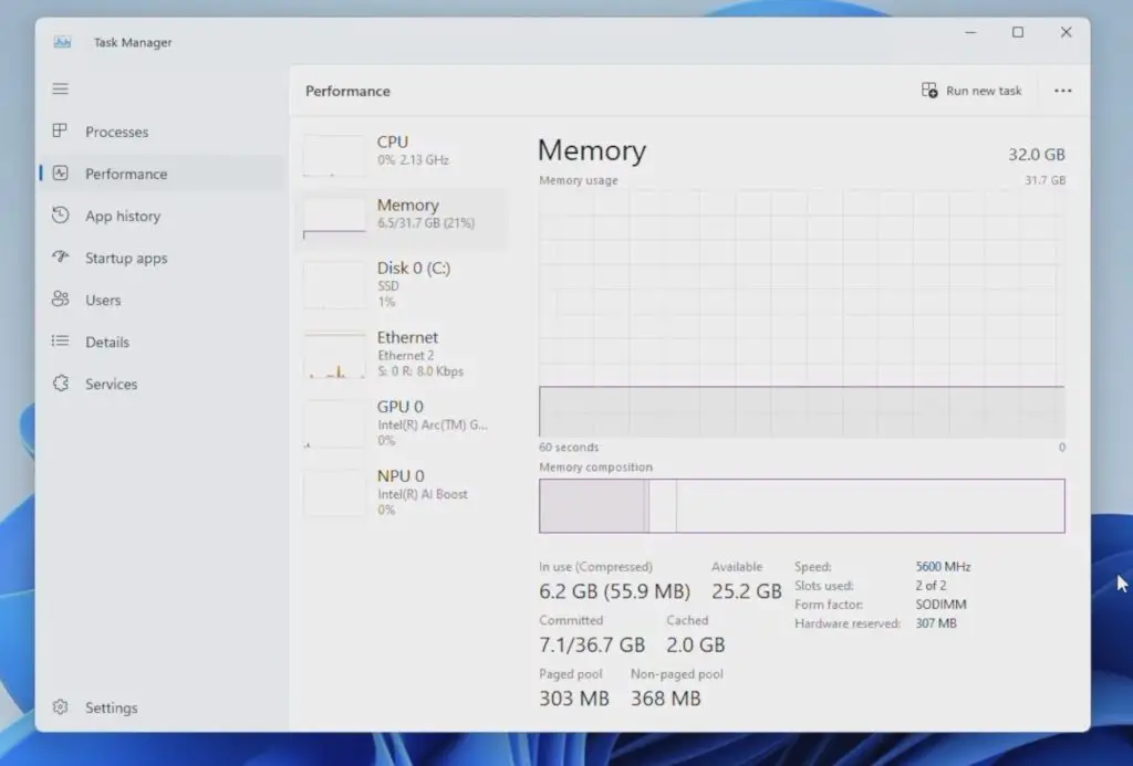
It’s got 32GB of DDR5 RAM running at 5600MHz and a 1TB NVMe SSD.
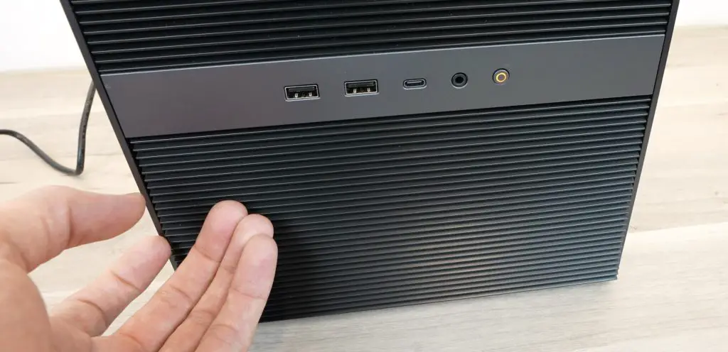
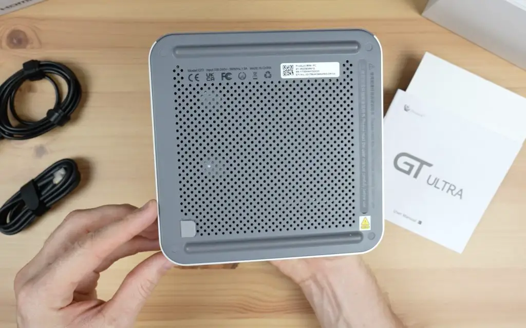
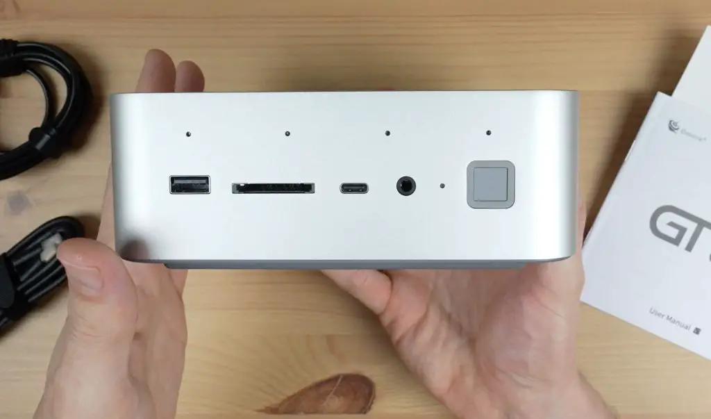
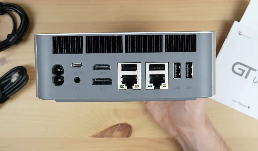
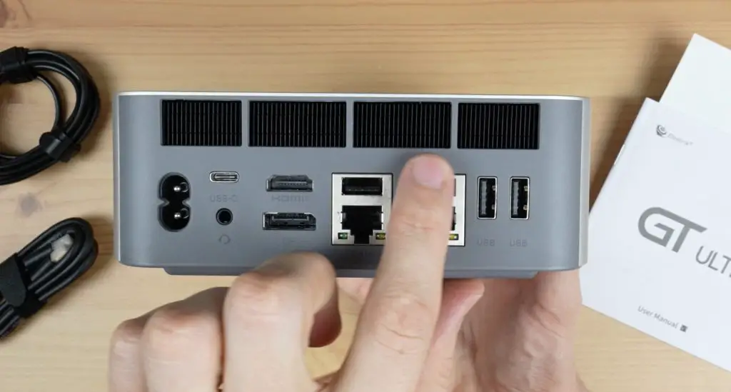
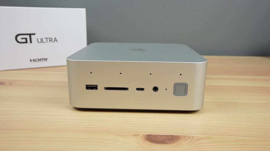
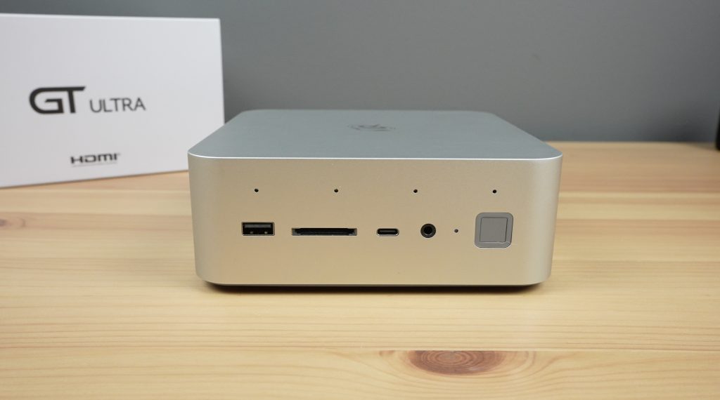
In terms of IO, on the front, we’ve got a USB 3.2 port, a full-size SD card slot, a USB C port, a 3.5mm audio jack, a power indicator LED and a power button. The power button also has an integrated fingerprint sensor on it. The four holes along the top are for a microphone array suited to voice recognition.
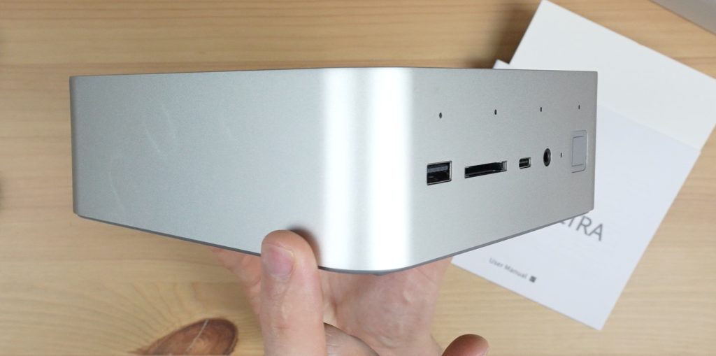
The two sides have nothing on them, they’re just bare aluminium.
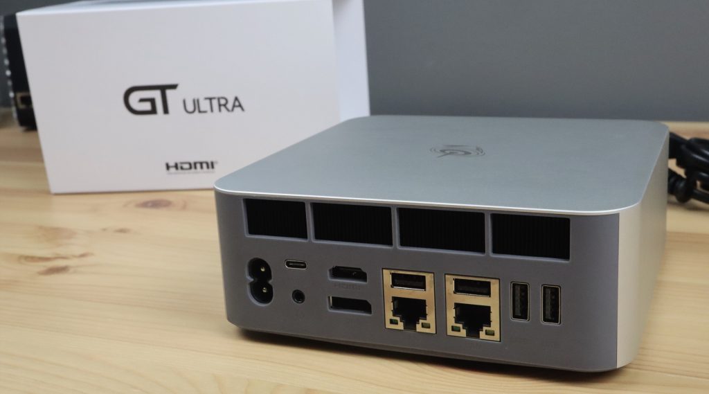
On the back, we’ve got our AC input, another USB C port (this one is a Thunderbolt 4 port), another 3.5mm audio jack, an HDMI port that can do 4K 60Hz, a DisplayPort that can do 4K 144Hz, two more USB 3.2 ports above two 2.5G Ethernet ports, and another two USB 3.2 ports alongside them.
In addition to the 2.5G Ethernet ports, it’s also got WiFi 7 and Bluetooth 5.4.
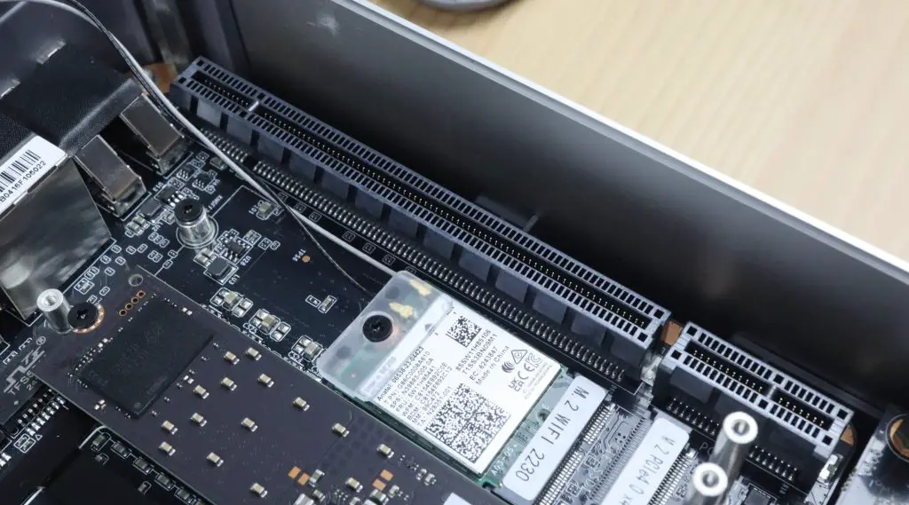
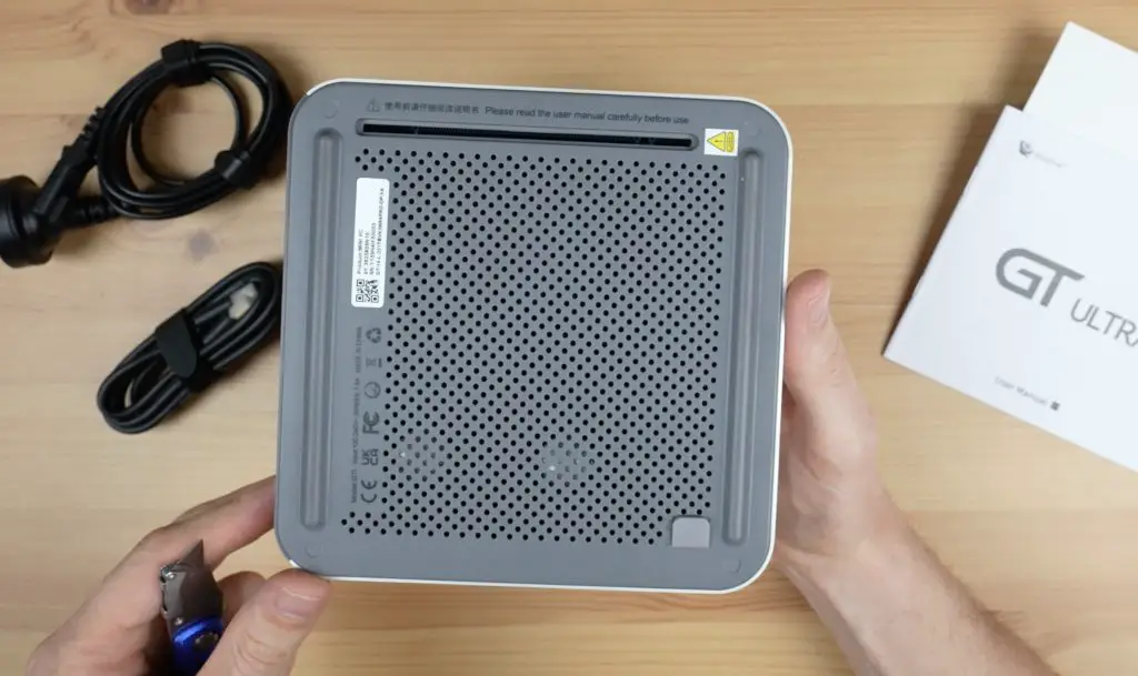
The last port, and the one I’m most excited to try out, is the PCIe gen 4 x8 slot, which is accessible through the bottom of the PC under a thin rubber cover.
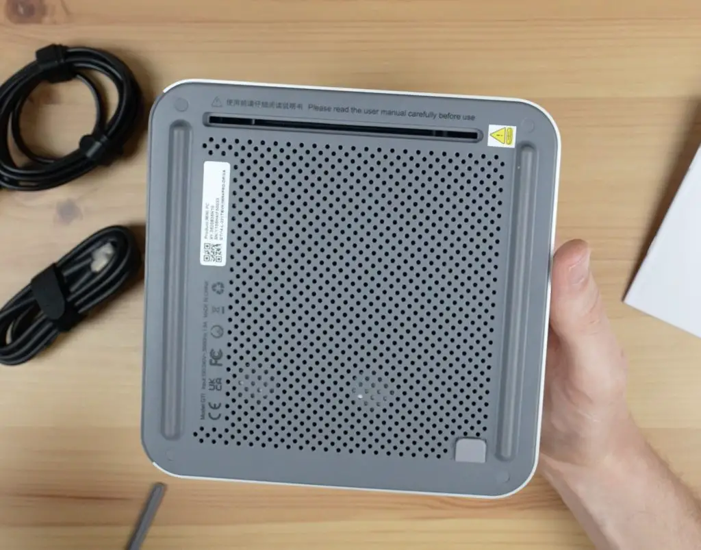
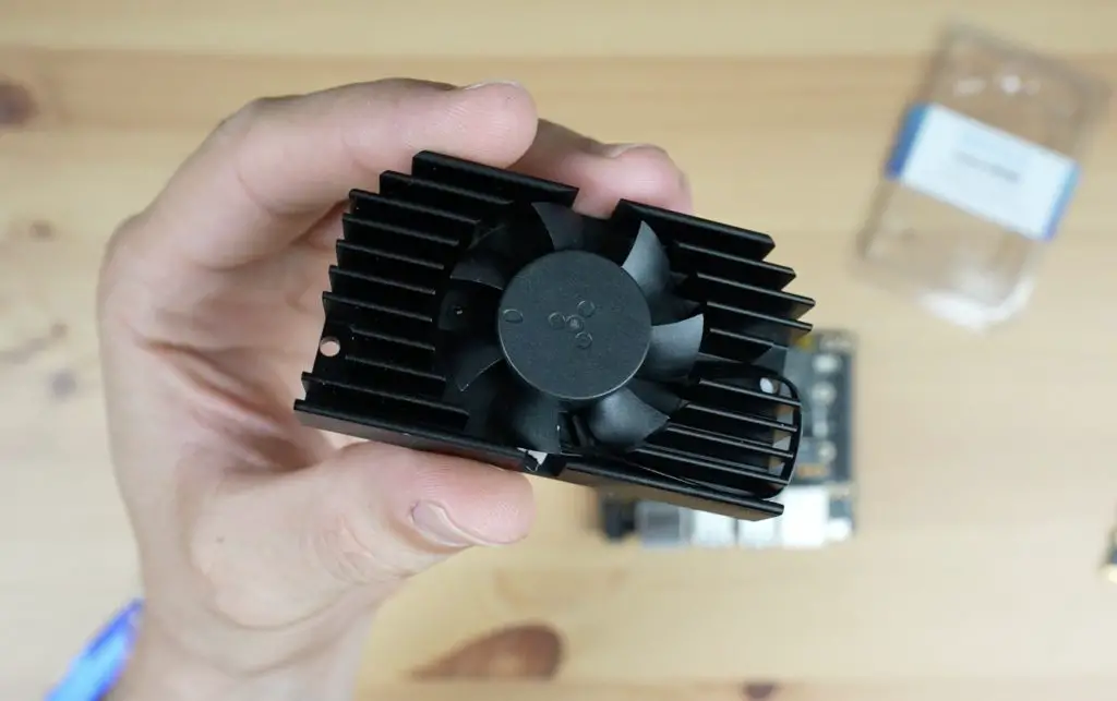
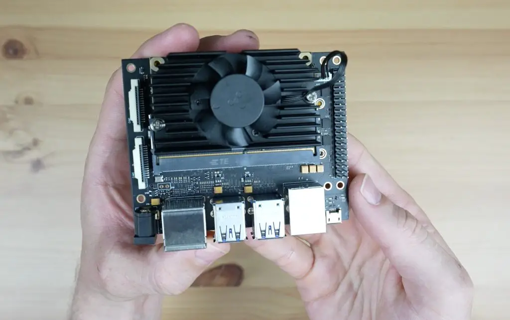
Cooling is achieved by drawing air in through the mesh on the bottom and then exhausting it through these vents at the back.
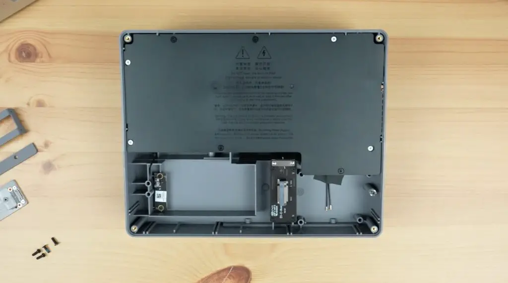
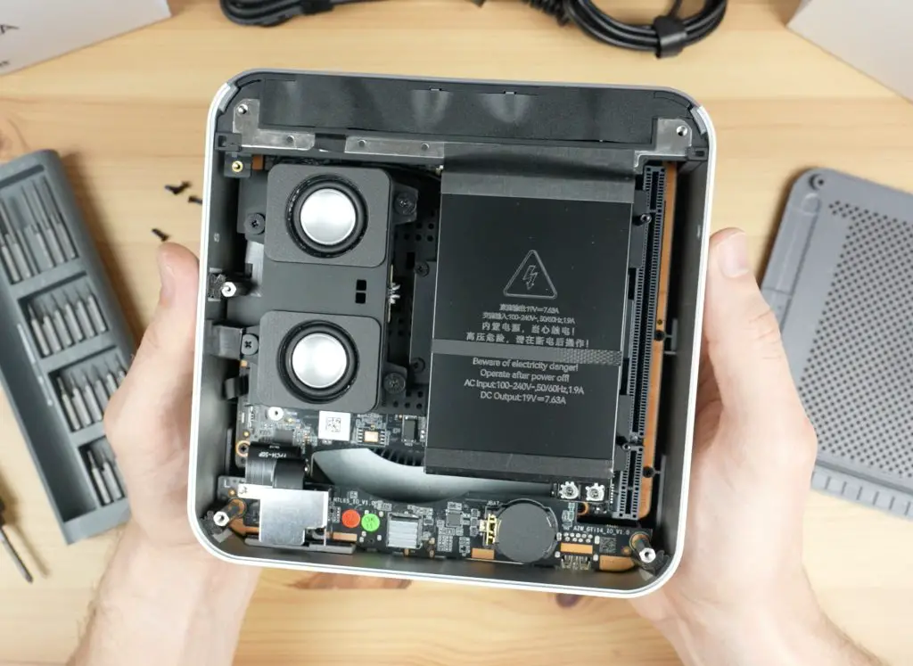
Taking A Look Inside The GTi 14 Ultra
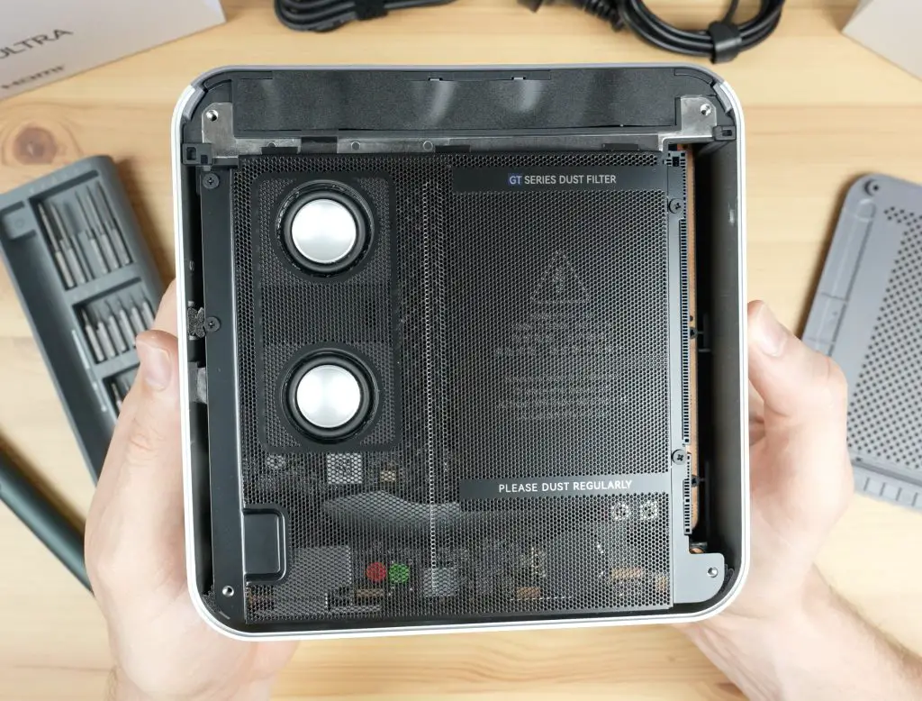
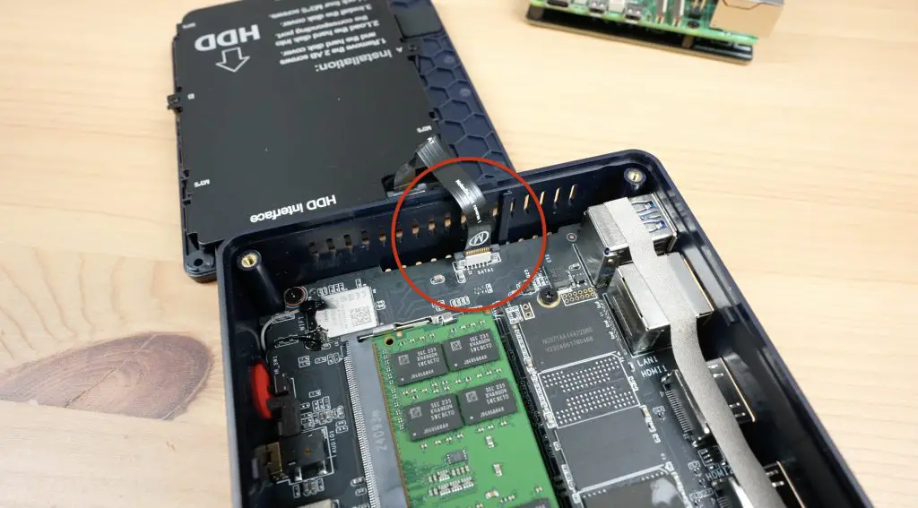
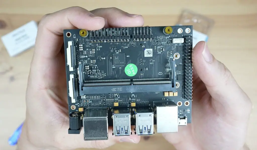
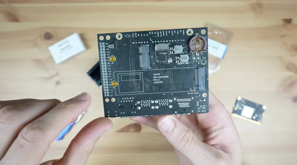
Next, let’s open it up and take a look inside. Four screws hold the bottom cover in place. With those removed, we can see two integrated speakers and a dust filter to protect the components.
Under the filter is the speaker assembly and our power supply. These make it a bit more difficult to get to the RAM and SSD, but I’m going to go ahead and remove them so we can get a good look at them.
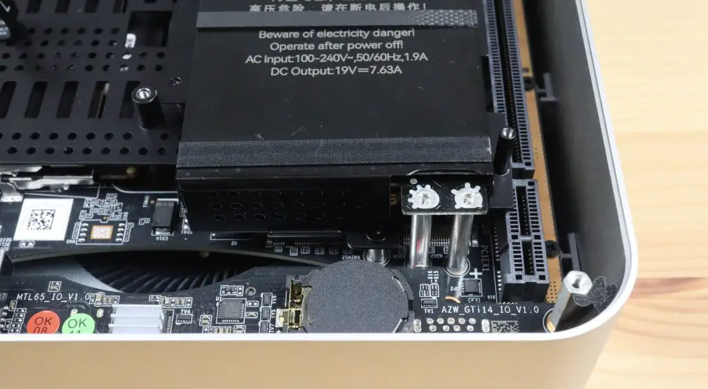
If you try this yourself, you need to remove the speaker assembly first. Once that has been removed, then remove the power supply. This is quite an interesting design. It gets AC power from the port at the back and then feeds 19V DC into the motherboard through these two standoffs. Lastly, remove the cover plate underneath them and then you’re in.
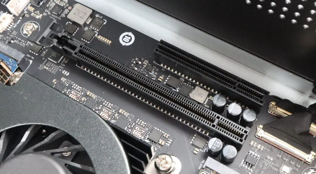
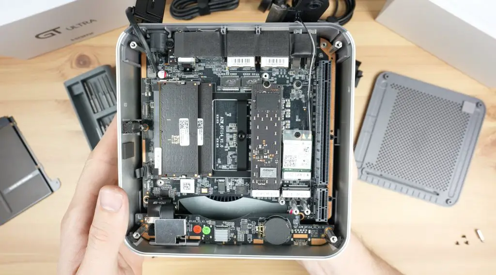
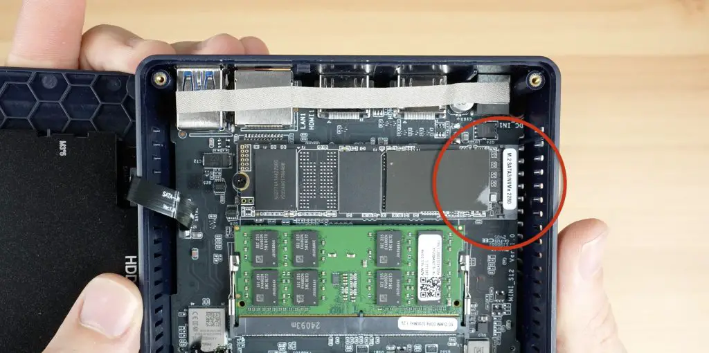
Then we can see our RAM and storage. The RAM is in a dual-channel configuration and is upgradable to a maximum of 96GB. There is also a second slot to add another M.2 NVMe storage drive. Alongside that is a removable M.2 WiFi adaptor and then our PCIe port. It looks like we’ve got a x8 and a x1 slot alongside each other.
First Boot and Benchmarking
Next, let’s close up the bottom cover and try boot it up. The GTi 14 Ultra comes with a clean install of Windows 11 Pro on it. Once set up, you can log in using the fingerprint sensor on the front, which is impressively fast.
I’ve had a look through the software and there doesn’t seem to be any preinstalled bloatware or spyware. You need to be careful buying mini PCs from Amazon or Aliexpress as they’re often filled with nefarious software. Beelink are a reputable brand and have been around for a while so they’re a safe bet.
Opening up the performance monitor we can see our CPU is an Intel Core Ultra 7 and it’s running at a base speed of 3GHz. We’ve got our 32GB of RAM running at 5600Mhz and our 1TB storage drive shows up as well. Our GPU is an Intel Arc and it’s sharing 16Gb of RAM.
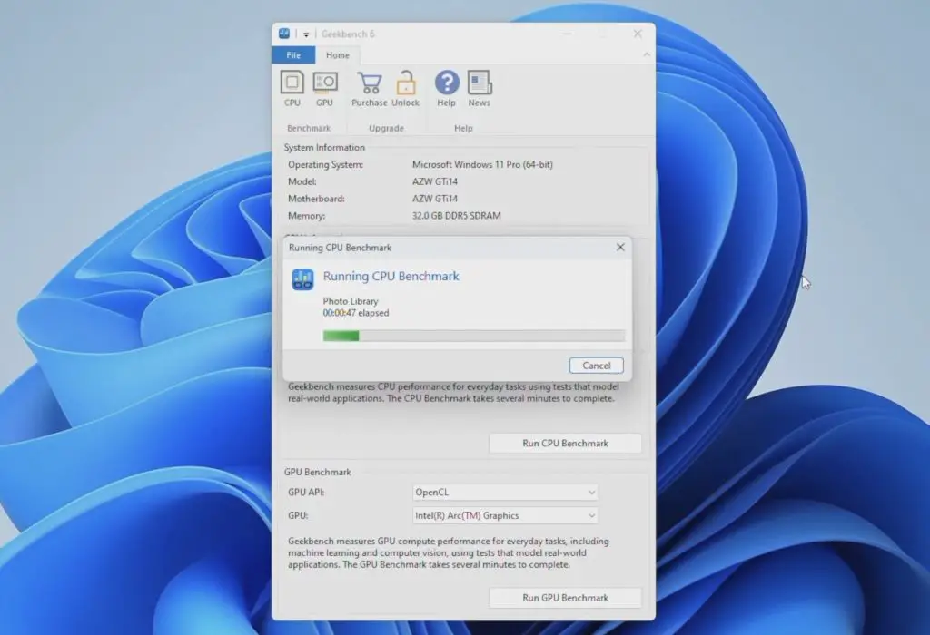
Next, we’ll run two benchmarks on it. The first is Geekbench to test CPU and GPU performance.
The CPU benchmark took 4:30 minutes to complete and the fan was surprisingly quiet throughout the benchmark. You could hear it running, but it’s nowhere near as loud as some other mini PCs I’ve tested. We get a single core score of 2,270 and a multicore score of 11,834. So single core scores are fairly average, but the multicore score is good.
The GPU benchmark took just under 2 minutes and we got a score of 37,460. This is very good for an integrated GPU.
Next, let’s run Furmark to test the computer’s GPU and thermals. Like with the Geekbench benchmark, the fan came on almost immediately but wasn’t all that loud for the duration of the test.
On completion, we get a score of 1,920. Unfortunately, the GPU temperature was unable to be recorded.
Gaming On The Stock GTi 14 Ultra
Now that we’ve run some benchmarks, let’s try running some games on it. We’ll start with Counterstrike 2.
It was handling the Home Screen pretty well so I set the graphics settings to Very High. In game, we get around 50-60fps, which is very playable. This is very good for a PC without a dedicated GPU and all settings on Very High. We’ll see how it compares when we add a GPU through the PCIe slot later.
Next, I tried running Doom Eternal. It had a bit of a freak-out when starting the game but it ran well after fixing the aspect ratio and setting the resolution back to 1080P.
I had all graphics settings on Ultra Nightmare and Ray Tracing turned off. In game, I was getting a little over 60fps fairly consistently, which is also really good.
Turning ray tracing on didn’t make a significant difference to performance, we lost about 10fps.
So for 1080P gaming on this mini PC, you really don’t need an external GPU. It does very well with the integrated Intel Arc graphics. Both games were easily playable, but we’re going to try to see how the PCIe port performs in any case.
So let’s plug our GPU into the GTi14 and get the AMD drivers installed.
Gaming On The GTi 14 Ultra With An External GPU
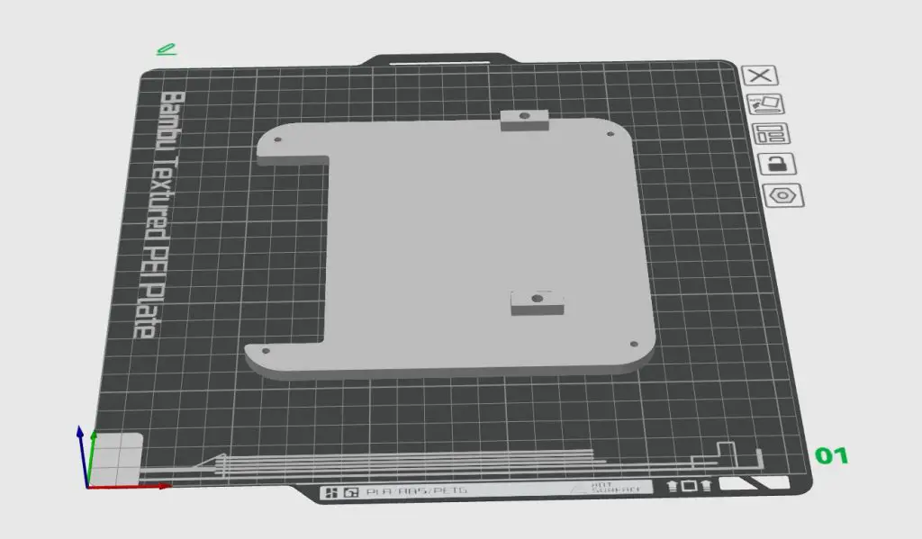
I 3D printed a new bottom cover for the GTi 14 Ultra which has some mounting points for a PCIe riser to plug the GPU into. I’m using a XFX Radeon RX 6600.
Adding The GPU To The GTi 14 Ultra
From the photographs on Beelink’s product page, it looks like they plan on selling an external GPU dock which will plug into the GTi 14 Ultra’s PCIe port. This isn’t yet available so I had to make another plan.
I 3D printed a new bottom cover for the PC. This picks up on the same cover plate screw holes but is offset with some M2.5x12mm standoffs.
I then plugged a Coolermaster PCIe riser into the PCIe port and mounted the female port onto the 3D-printed cover plate with some M3x8mm screws into M2.5 brass inserts.
In Counterstrike, with graphics again set to Very High, we’re now getting over 200 fps. This is 3 times what we were getting on the integrated GPU. The game is responsive and the PC seems to be running a bit cooler, the fan is noticeably quieter.
Next, let’s try Doom Eternal. Again with the same Ultra Nightmare graphics settings and Ray Tracing turned off, we’re getting over 150fps. This is about 2.5 times better than on the integrated GPU. I also noticed significantly faster load times with this setup.
Testing Power Consumption & Speakers
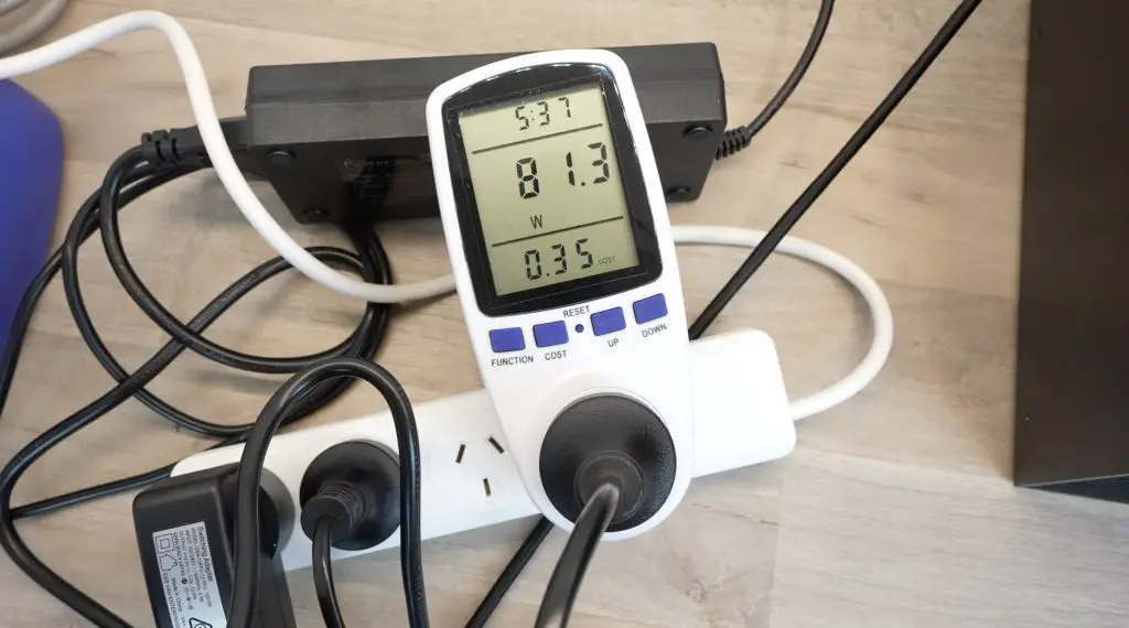
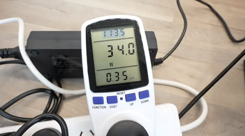
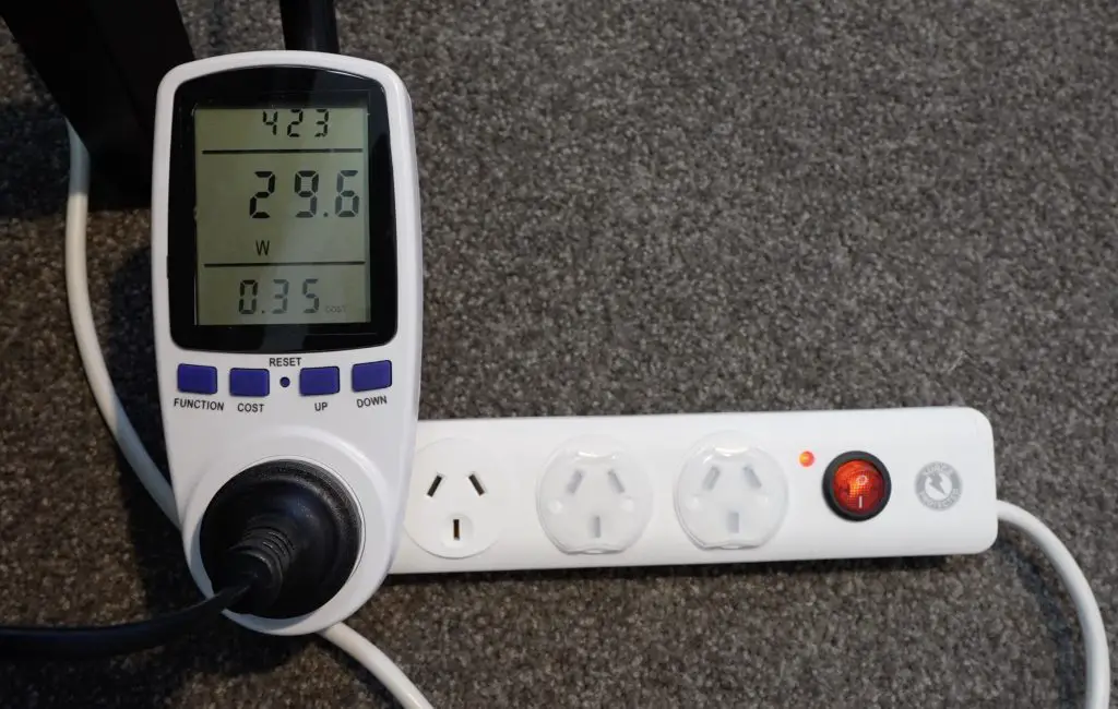
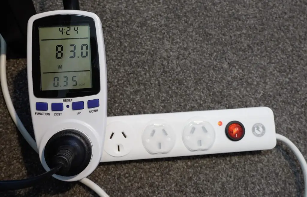
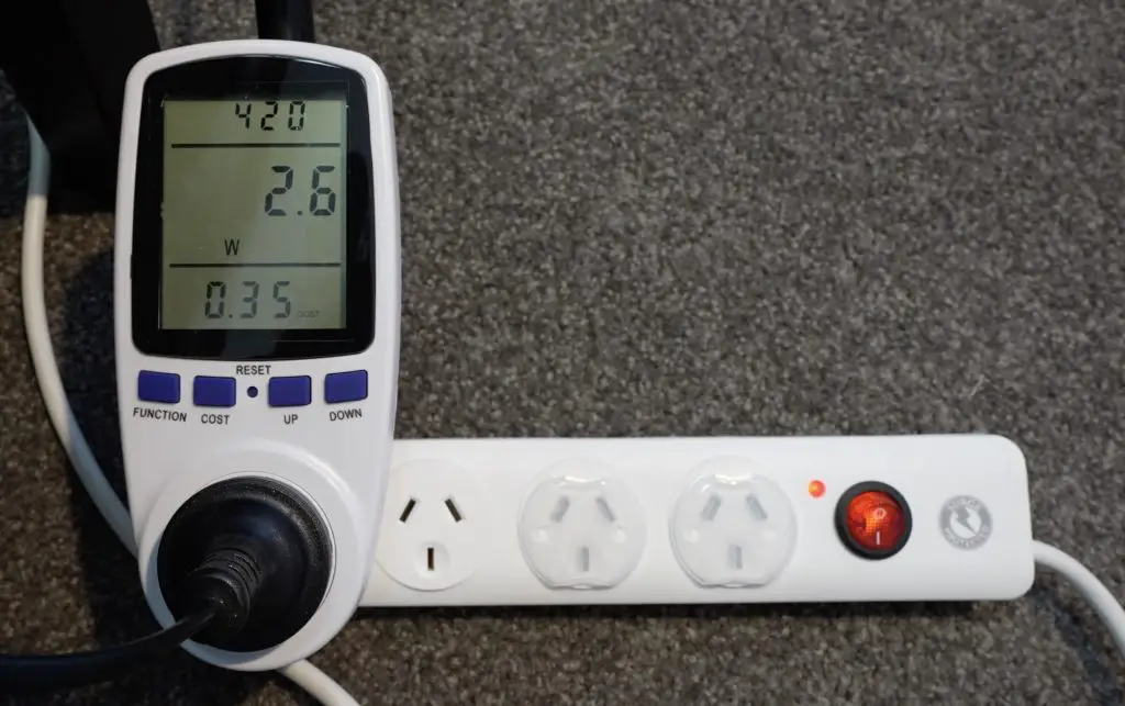
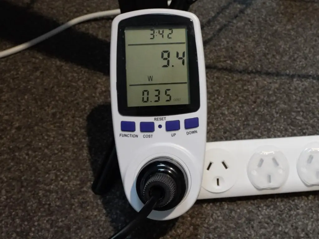
With the PC returned to its stock state with nothing plugged into the PCIe port, the GTi 14 Ultra uses around 30W when idle on the desktop. It maxes out at a little over 80W with the GPU and CPU being utilised during gaming.
Power Consumption Idle
The built-in speakers are a nice inclusion. They lack base because of their size but don’t sound terrible. They’re about on par with a mid-range laptop. You can hear a sample of the audio in my Youtube video.
Final Thoughts On The Beelink GTi 14 Ultra
Overall I think that this is a really awesome mini PC. It’s ultra-portable and having the ability to plug a GPU directly into it gives you the flexibility to use it for some fairly demanding gaming when you’ve got a bit more desk space and don’t need to carry it around. It’s also upgradable with non-soldered RAM and an additional M.2 port.
I have two criticisms though.
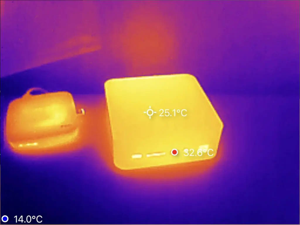
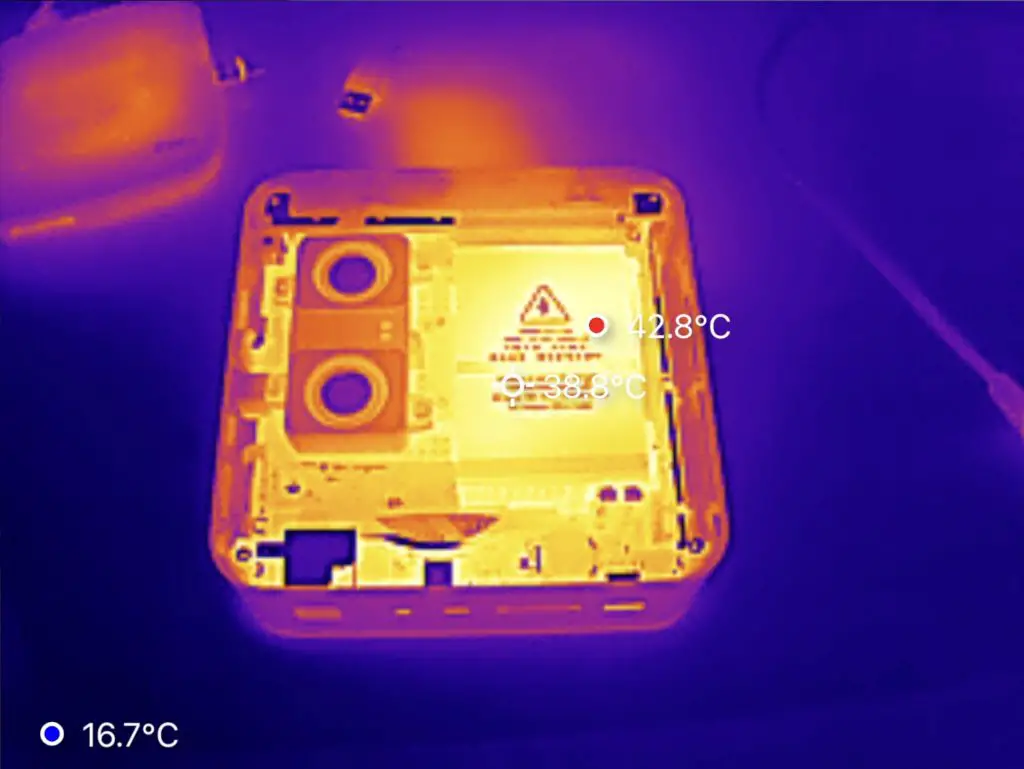
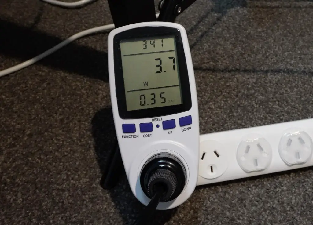
One is that the integrated power supply doesn’t seem to go into a proper dormant or sleep state, even when the PC is completely shut down. In the below images, it had been off overnight and the enclosure was still noticeably warm. The power meter registers about 2.5W with the computer shutdown, so it’s using power for no reason.
The second is the implementation of the PCIe slot. It is very deeply recessed in the enclosure and the access slot through the enclosure is too thin for most standard risers. I assume that Beelink are going to release some sort of proprietary dock, but it would have been nice to have the slot easily accessible through the bottom cover with a standard riser cable.
I’m not sure what the pricing is going to look like as they’re not yet for sale at the time of writing, but I’d imagine they’ll be around $800 for the Ultra 7 series and likely $100 more for the Ultra 9 series.
Let me know what you think of the GTi14 Ultra in the comments section below. What would you use it for?
On a couple of my YouTube videos since the launch of the Raspberry Pi 5 last year, people have said that for the price of the Pi 5, you should just get an Intel N100 based mini PC instead. Most cite better video encoding and decoding performance, better OS support, more memory & storage options, and additional PCIe lanes as advantages over the Pi 5. So, today we’re going to compare the two and see whether an N100 Mini PC is a better option and what the limitations of each of them are.
If you don’t know what an N100 PC is. It’s a PC, often in a mini PC form factor, that is built around Intel’s Alder Lake N family, and in this case the N100 CPU. For a long time, Rapsberry Pi’s were substantially cheaper than any newly available Intel hardware, but Pi’s have since crept up in price and this series of processors are now cheap and efficient enough to close that gap to the point whether they’re becoming quite comparable.
Here’s my video of the comparison, read on for my write-up;
For this comparison, I’m going to be using the following two setups.
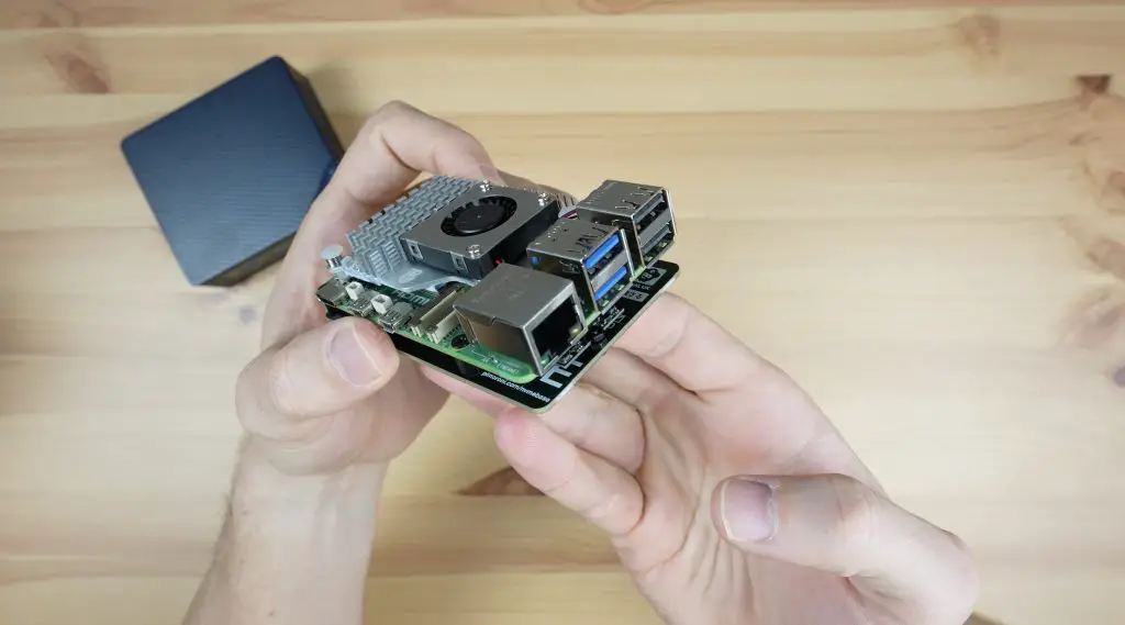
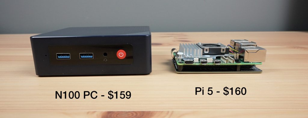
The Pi 5 is an 8GB variant and I’m going to be booting it up from a Pimoroni NVMe base with a Lexar 500GB NVMe SSD. I’ve also added an official active cooler and power supply which, along with the NVMe base and storage drive, comes to a total of $160.
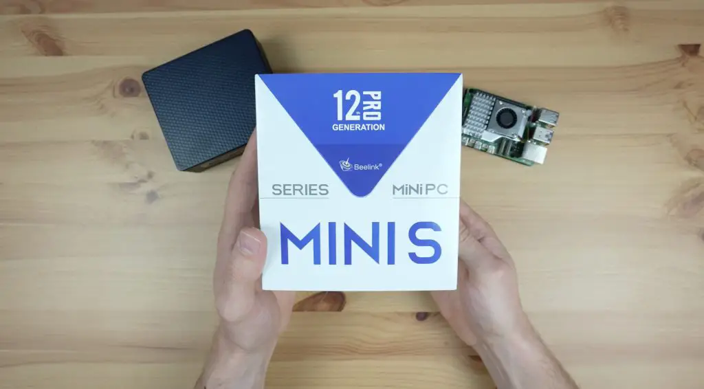
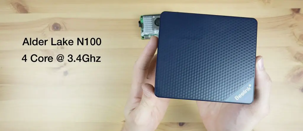
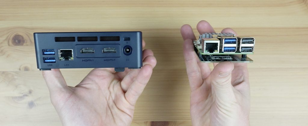
The N100 PC I’ve chosen is the Beelink Mini S12 Pro. This was on special for $159 when I bought it, so it was one of the cheapest options available on Amazon at the time. There were two cheaper options for $154 and $155 but I didn’t recognise either of these brands and I’ve used Beelink products before without any issues so I was happy to pay the extra $5.
So pricing between the two is really similar once you’ve added all of the required components to the Pi 5 and with the N100 we’re getting double the RAM and an included enclosure.
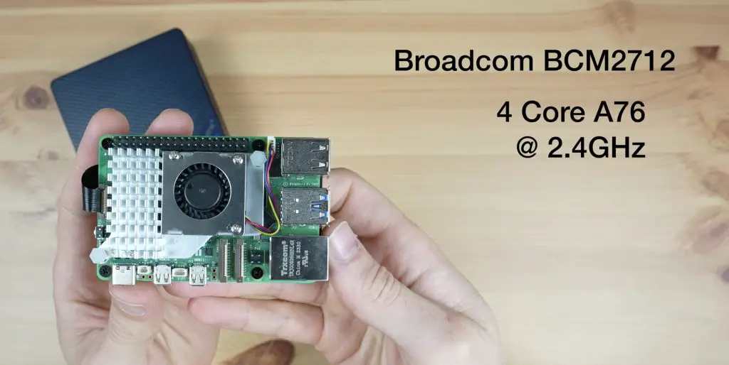
In terms of basic specifications, the Pi 5 has a Broadcom BCM2712 SOC which has a 4-core Arm A76 processor running at up to 2.4Ghz. It’s also got a Videocore VII GPU.
The N100 has 4 4-core Alder Lake N processor running only Intel E cores at up to 3.4GHz and integrated UHD graphics.
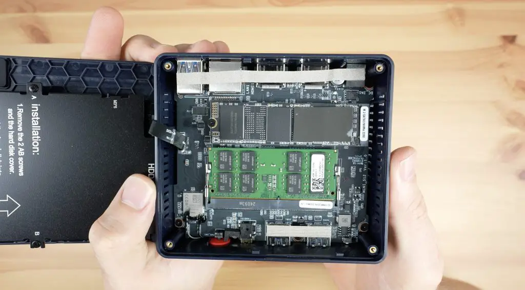
Both of these computers have DDR4 RAM. The Pi 5 has 8GB running at 4267 MT/s and the N100 PC has 16GB running at a slower 3200 MT/s.
In terms of storage, both have a 500GB NVMe SSD.
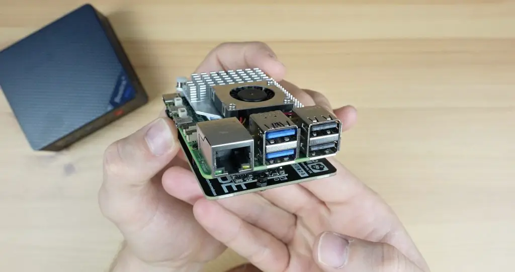
Both computers have similar connectivity options – Gigabit Ethernet, two HDMI ports and four USB ports, although two on the Pi are USB 2.0 instead of all four being USB 3.0 like on the N100 PC.
They both have an M.2 port for an NVMe drive but the N100 also has a SATA port for a 2.5” drive and the Pi has a couple of other interfaces like dual 4-lane camera/display transceivers and a 40-pin GPIO header – we’ll discuss this in a bit more towards the end of the comparison.
The Pi 5 has a single PCIe lane that can run at gen. 3 speeds, to which the NVMe drive is connected. The N100 PC has a built-in M.2 port which makes use of 2 PCIe lanes also running at gen. 3 speeds. So we’d expect the storage speed on the N100 PC to be quite a lot faster than the Pi.
Perhaps the most significant difference between the two is that the N100 is an Intel X86-based system while the Pi 5 is an Arm-based system, so you’ve got far more options for compatible operating systems on the N100 PC than on the Pi 5.
To make testing fair, we’ll be running Ubuntu on both since Ubuntu Desktop 24.04 is available as an officially supported OS through Raspberry Pi Imager and is available for the N100 mini PC as well.
Testing The Pi 5 & N100 PC
To compare the performance of the two, we’re going to run the series of tests below. These should give us a pretty good idea of the capabilities and limitations of each system.
Video Playback at 1080P in a Browser
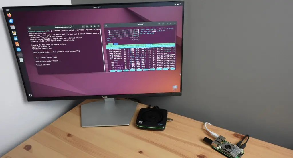
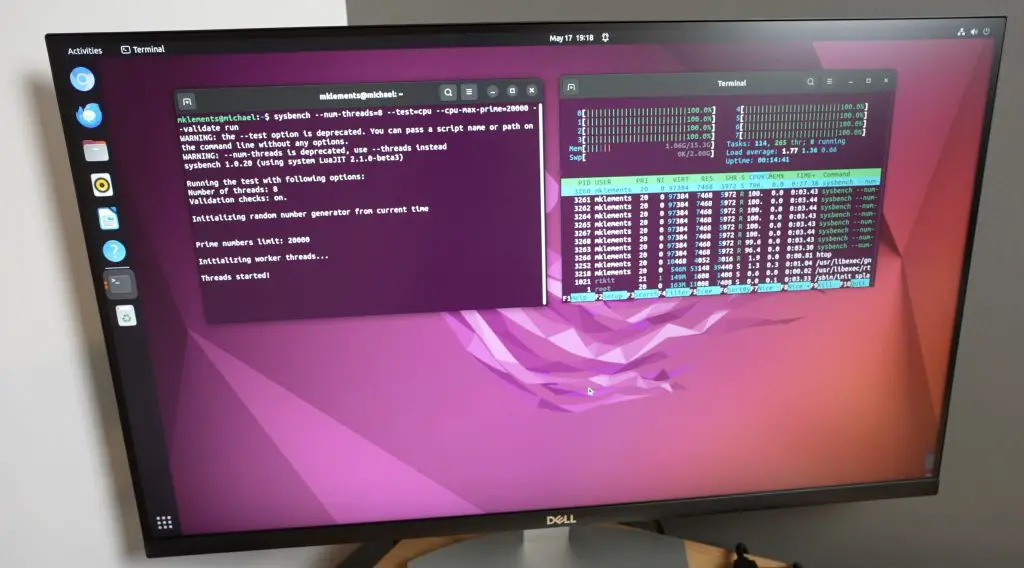
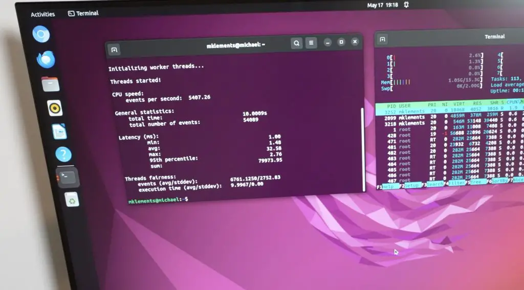
A Sysbench CPU Benchmark
An NVMe Storage Speed Benchmark
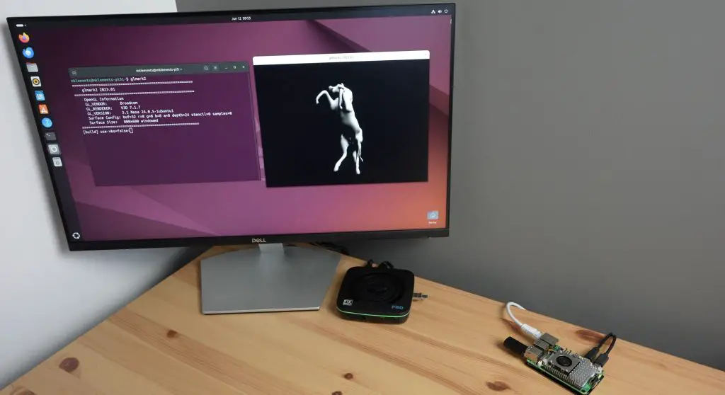
GLMark2 GPU Benchmark
Power Consumption Test
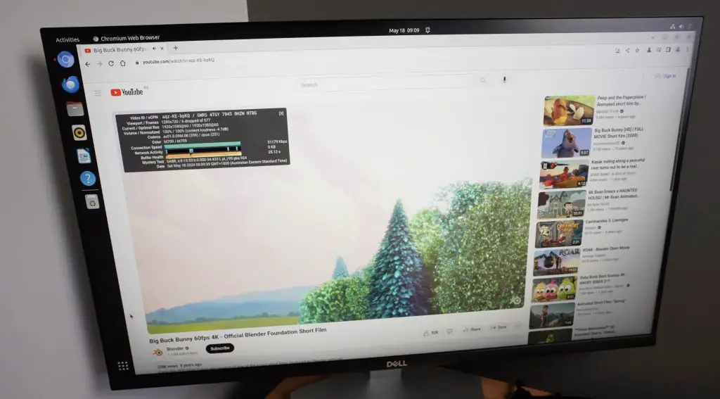
Video Playback at 1080P
Let’s start with video playback at 1080P.
The Pi 5 struggled with this more than I expected it to. It stuttered badly and dropped a significant number of frames at the beginning. Even once playback settled, it still continued to drop frames.
From my experience, the Pi 5 handles video playback in Raspberry Pi OS, which is based on Debian, without any issues, so this is most likely a software issue.
The N100 PC had no problem playing back the 1080P video. Playback was smooth right from the start and was unaffected when running in the window or fullscreen.
So both can handle 1080P video playback but the N100 PC is much better at it.
Sysbench CPU Benchmark
Next, let’s run a Sysbench CPU benchmark. I ran three tests on each computer and then averaged the scores.
I ran the following test on each of the computers;
sysbench --num-threads=4 --test=cpu --cpu-max-prime=20000 --validate run
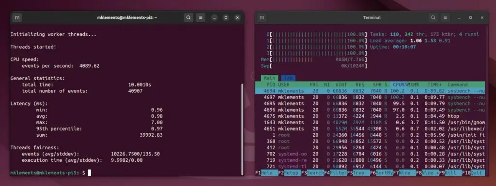
The Pi 5 managed an average score of 40,359
Actual scores – 40907, 40023, 40148
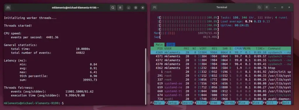
The N100 PC managed an average score of 44,058
Actual scores – 44022, 44096, 44056
So the N100 PC was about 9% faster than the Pi 5. This is not as significant as I was expecting given the much higher clock speed on the N100’s cores, but there is a small CPU performance gap between the two.
The N100’s results were also far more consistent than the Pi 5, which may suggest that the Pi encounters some sort of thermal limitations when running the tests in quick succession.
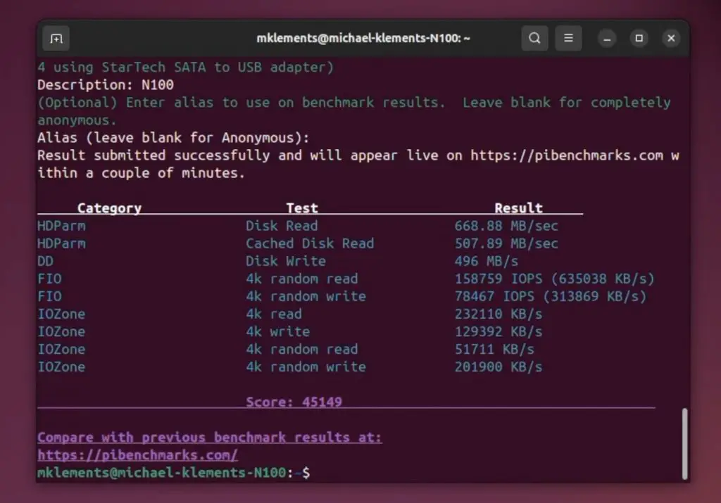
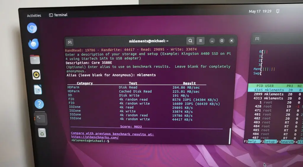
NVMe Storage Speed Benchmark
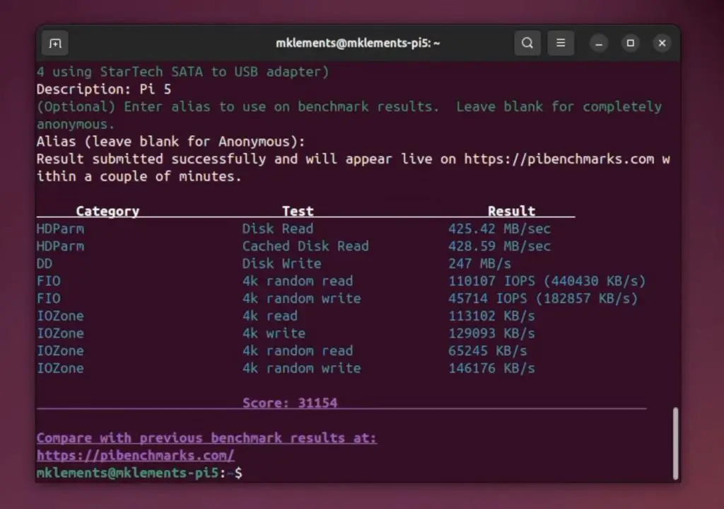
To test the NVMe storage speed, I used James Chamber’s Pi Benchmarks script. This script favours random read/write performance, so is a good representation of how an operating system would make use of the drive.
To run the test, enter the following command in the terminal;
Over three tests, the Pi 5 managed an average score of 32,089 with average sequential read speeds of 423MB/s and average sequential write speeds of 241MB/s.
Actual scores 31154, 32431, 32683
Actual read speeds 425, 432, 412
Actual write speeds 247, 239, 237
The N100 PC managed an average score of 44,803, so significantly higher than the Pi 5, with an almost 40% improvement. Average sequential reads were around 673MB/s and average writes 495MB/s.
Actual scores 45149, 44992, 44267
Actual read speeds 668, 669, 683
Actual write speeds 507, 491, 487
GLmark2 GPU Benchmark
The N100 has a much more powerful GPU, so I expect it to do a lot better than the Pi in our GLMark2 GPU benchmark.
This benchmark needs to be downloaded and built from source code, and is then run by entering the below command in the terminal;
glmark2
The Pi 5 managed a score of 307.
The N100 PC managed a score of 2070.
So the N100 is over 6 and a half times faster than the Pi 5 in GLMark2, which is obviously a substantial difference.
Power Consumption
Lastly, let’s look at power consumption. This is where I have high hopes for the Pi to stand out.
At idle the Pi 5 uses around 3-4W, and this goes up to 8-9W under load.
The N100 PC uses quite a bit more power, using 8W idle on the desktop and up to 27W under load.
While neither of these figures are particularly high, it’s worth noting that the N100 uses nearly four times the power of the Pi 5. This probably makes little difference on mains but for battery-powered projects that are required to run for many hours or even a few days, the difference can lead to substantial savings in power supply hardware and batteries. This is not all that surprising – ARM computers are known to be power efficient, which is one of the reasons they’re so popular for mobile devices.
Conclusion & Final Thoughts
So, the N100 PC beats the Pi in almost every performance benchmark and comes in at a similar cost.
One of the main reasons that people list for getting a Pi over an N100 PC is the GPIO pins, and these are without question much easier to use on the Pi. The GPIO pins are literally available right on the board and there is a wealth of software and tutorials available to utilise them.
That doesn’t mean that you’re out of options for the N100 PC. Microcontrollers like an Arduino Pro Mini or Nano, or even one of these purpose-built Adafruit FT232H USB to GPIO breakout boards make it equally possible to connect tiny OLED displays, read in information from sensors or just work through an introductory flashing LED tutorial on a PC, with relative ease.
This is not as integrated as on the Pi and comes at an additional cost, but for a few dollars might be worth it if you’re just getting started tinkering with electronics.
So, if you plan on using the computer for automation or robotics with a reliance on the GPIO pins then the Pi 5 is the better option, but for experimenting with home server projects, running anything reliant on a GPU, or getting started with Docker or Kubernetes then the N100 mini PC is a great alternative.
I think Raspberry Pi have missed the mark a little with the pricing of the Pi 5. If you are just looking for a cheap computer to get into tinkering with electronics projects then you’re probably better off going for a base version of the Pi 4. This still has plenty of CPU power to run projects locally and you’ll have access to a similar set of IO to the Pi 5 but without the additional cost. After all, a big part of the initial attraction to Raspberry Pi’s was the $35 base price!
Let me know which you prefer and what your use case is in the comments section below.
Today we’re taking a look at the Mixtile Core 3588E. This is a new system on a module, based on the Rockchip RK3588. It’s in the same 69.6 x 45mm form factor as the NVIDIA Jetson TX2 NX module and uses the same 260-pin edge connector – so is compatible with many of the same carrier boards.
Here’s my video review and testing of the Core 3588E, read on for my written review and results:
In the centre of the module, we’ve got the Rockchip RK3588 processor. This is an 8-core, 64-bit processor that consists of a 4-core Cortex A76 processor running at 2.4GHz and a 4-core Cortex A55 processor running at 1.8GHz. In addition to this, it’s got an Arm Mali G610 GPU.
Alongside it is the eMMC storage module and on the other side of the CPU are the LPDDR4 RAM chips.
The Core 3588E comes in three configurations;
4GB of RAM and 32GB of storage selling for $132
16GB of RAM and 128GB of storage selling for $190
32GB of RAM and 256GB of storage selling for $329
This is quite pricey for a module with this processor on it, given that you can buy a full SBC with ports broken out for this price. But they are fairly close to the pricing on the Turing RK1 modules with the same SOC, so let’s see how it performs.
On the bottom is the 260-pin SO-DIMM connector which allows it to be plugged into devices and carrier boards.
The carrier board that you use will obviously determine which ports and interfaces are available, but the 3588E supports the following basic IO;
HDMI and display port interfaces up to 8K60
USB3.0
USB2.0
PCIe 3.0
PCIe 2.1
UART, SPI, I2C, CAN, I2S, PWM and
Digital IO pins
The carrier board that I’m going to be using with the Core 3588E is the A206, which is designed for NVIDIA Jetson modules.
The main IO is all brought out on one side, with a power input on the left that supports a 9 to 19V DC supply. Alongside it, we’ve got a display port and HDMI port, 4 x USB 3.0 ports, and a Gigabit Ethernet port. The microUSB port at the end is for reflashing the boot loader.
On the top of the carrier board, it has a set of GPIO pins along the right side, a set of pins for buttons and the CAN interface at the back and two camera inputs on the left.
On the bottom is a M.2 E key port as well as an M.2 M key port, an RTC battery holder and a microSD card slot.
Also available for the Core 3588E is an optional heatsink with a built-in PWM fan which plugs into the carrier board. The heatsink is attached directly to the Core 3588e with some small screws that go into thread inserts on the SOM. They provide thermal paste to apply between the CPU and heatsink for improved conductivity.
I’m going to test this board in a similar way to other SBCs that I’ve tried on this channel. I’ll also show you it running a pre-trained AI model to recognise objects in images as this is primarily what these modules are intended to be used for.
We’ll first test some video playback at 1080P, then try to run a Sysbench benchmark, then run a storage speed test, then the AI object detection model and finally we’ll take a look at power consumption.
After the Mixtile Core 3588e has booted up, if we open up HTOP, we can see we have 8 processor cores and our 16GB of RAM. The processor is currently under very little load, being idle on the desktop.
Video Playback At 1080P
First let’s try playing back a YouTube video in Chromium, which I’m going to do at 1080P. We can open up Chromium, go to YouTube and play Big Buck Bunny. I’ll open up stats for nerds and set the playback resolution to 1080P as well.
Video playback in the window is pretty good. We dropped quite a few frames in the beginning but after that playback settles and is very stable and usable.
It’s also pretty good running full screen. It again dropped quite a few frames in the beginning and then settled down.
If we open up HTOP, we can see that we’re averaging less than 30% CPU utilisation on the first 4 cores, which is relatively low compared to the other RK3588 boards that I’ve tested.
The optional heat sink and fan do a good job at keeping the Core 3588E cool. After 20 minutes of 1080P video playback on YouTube, the CPU was only at 47 degrees and the heatsink was at 38 degrees.
Sysbench CPU Benchmark
Next let’s do a CPU performance comparison with the Mixtile Blade 3, Rock 5 B and Orange Pi 5 Plus which all run the same RK3588 SOC. We’ll do this by running the Sysbench CPU benchmark.
After 10 seconds we have processed a little under 5400 events per seconds and we get a total score of 54,089. Over three tests we get an average score of 54,083.
For comparison, also over three consecutive tests;
Mixtile Blade 3 managed an average of 54,025
Rock 5 B managed an average of 53,642
Orange Pi 5 Plus managed an average of 53,436
So the results from the Core 3588e are slightly higher than the other boards I’ve tested but this is not a significant improvement. It is likely because we’re running a different OS this test was run on Ubuntu and all of the others were tested on Debian.
eMMC Storage Benchmark
Next, we’ll run James Chamber’s Pi Benchmarks script to test the speed of the onboard eMMC storage. This benchmark favours better random read/write performance because this is a good representation of how the storage or drive would typically be used as an OS drive rather than just reading or writing single large files to it.
On completion of the test, we get a total score of 9,822. The individual test results are also listed in the image below.
The results aren’t great, sequential read speeds are around 264MB/s and writes are around 225MB/s. Random reads and writes are 13 times and 5 times slower respectively. A better option would probably be to boot from an NVMe drive on the carrier board, but the eMMC storage is ok for an onboard solution if you aren’t transferring large amounts of data.
AI Object Detection Model
Now let’s try an AI object detection model. This is a pre-trained model that you send an image to and it then analyses the image to see if any objects that it has been trained to identify are present.
Here is a list of the objects that the model can detect (each row being a category);
I’ve got five test images prepared. We’ll try to put each of these through the model and it’ll produce an output image that shows any detected objects and the model’s confidence in its classifications.
Image 1 is a photograph of 3 elephants;
The image took 18 ms to process, which is impressively fast. It would be able to process around 55 frames per second at this speed.
And this is the result. It got all three correct with a fairly high level of confidence.
Image 2 is a woman in front of a pedestrian crossing with some traffic in the background.
This too took 18 ms to process and the results are pretty good. There is a lot going on in the background but the main elements in the foreground and centre are all correct. Even some of the more obscure background objects are correct.
Image 3 is a similar traffic image.
This has got most of the main elements correct and even a number of the partially obscured cars are correctly identified.
Image 4 is a basket of vegetables with some oranges in front of them.
It made a few mistakes here. I’m not even sure why – these look nothing like an apple or carrot. The confidence levels are pretty low so it clearly had trouble working through these areas.
The last image is a dinner table.
Again this image is mostly correct, even recognising that the whole image is of a dinner table. The knives on either side have been missed and have jointly been labelled a spoon with the spoons next to them. The fork on the far side it got right despite the low confidence.
Power Consumption
Lastly, let’s take a look at power consumption. To measure the Core 3588E’s power consumption, I used a mains power meter. This indicates that the Core 3588E uses about 4W when idle and this goes up to 9W when loaded.
This is a bit higher than the Blade 3 but it does have an active cooler on it and a few extra circuits on the carrier board as well, so is expected but still quite power efficient.
Final Thoughts On The Mixtile Core 3588E
Overall I think that, similar to the Blade 3, the Core 3588E is quite expensive, especially considering it is a bare module and you’d still need to add a carrier board or have a device to plug it into to use it. They have again used good quality components, so you should get good reliability and life out of it, and the module is similarly priced to some alternatives like the Turing RK1 modules.
With the RK3588 SOC, performance is really good, especially considering its low power consumption. This module is ideal for applications like live object detection or motion tracking on a video feed.
Let me know what you think of the Mixtile Core 3588E in the comments section below and if there is anything else that you’d like me to try on it.
Last year, I built a Pi-based NAS as cheaply as possible using a Raspberry Pi Zero 2W. It was a great project to learn what a NAS is and how to set one up, but it was obviously limited by the capability of the Zero 2W and the cheap storage hardware that was used. So, today we’ll be building a more functional and powerful NAS using a Raspberry Pi 5.
Here’s my video of the build, read on for the write-up;
Some of the above parts are affiliate links. By purchasing products through the above links, you’ll be supporting this channel, at no additional cost to you.
Hardware Used To Build The NAS
The primary piece of hardware that we’ll be using to build the NAS, apart from the Pi 5, is this new Penta SATA hat from Radxa. This hat allows up to 5 SATA drives to be connected to a Raspberry Pi 5 or Rock 5A via their PCEe port.
It’s got 4 SATA ports on the top, which drives plug into top-down, and one eSATA port on the front. Radxa include a cable to plug a fifth drive into this port with the hat. The spacing between the SATA ports allows for 2.5″ drives to be plugged directly into it, but you can also connect 3.5″ drives to it with some extension cables.
Power is supplied to the hat through either a 12V barrel jack on the side or a standard ATX Molex connector on the top. Additionally, you don’t need a second power supply for your Raspberry Pi 5 – the hat will supply 5V to the Pi through the GPIO pins. That’s a really handy feature!
The Penta SATA Hat has got a couple of other ports on it too, like an expansion port for a fan and OLED display on top and an additional fan port at the bottom.
Before mounting the hat onto the Pi 5, we need to add a cooling solution for the Pi’s CPU. I’m going to use a Pi 5 active cooler.
There is one issue with using this cooler and that’s that the end three fins on the heatsink clash with the barrel jack port on the hat. This seems like a bit of an oversight by Radxa but hopefully, they’ll come up with a solution to correct this in future revisions.
My first thought was to add some 6mm spacers between the hat and Pi so that there is a larger air gap between them. This however isn’t possible without also requiring an adaptor for the GPIO pins to still plug into the hat.
The only easy solutions are to either get rid of the cooler or modify the cooler to fit in underneath the connector. Modifying the cooler can be done relatively easily by removing the last three fins, which you can break off with needle nose pliers.
For storage, we’ll use some Crucial BX500 drives as I think these strike a reasonable balance between cost and quality. We’re going to be bottlenecked by the single PCIe lane shared between the drives so there isn’t much point in getting the fastest drives available, any reasonably good quality 2.5″ SSDs would work for the build.
Lastly, we need a microSD card for the operating system. We’ll use a 32GB Sandisk Ultra card for this. I’ve been using these for my Pi projects for years and have had very few issues with them.
I flashed the microSD card with Raspberry Pi OS Lite using Raspberry Pi Imager. This is the base operating system onto which we’ll be installing the NAS software Open Media Vault or OMV. When flashing the operating system image, you may want to change the name of your NAS and you’ll need to enable SSH so that you can log into the Pi remotely once it has booted up to install OMV onto it.
Radxa include hardware with the hat to secure the drives to each other. These make the drive stack a bit more secure, but I’d like to build the stack into an enclosure to better protect the Pi and Penta SATA hat, and provide some cooling to the drives.
Designing The Enclosure
To design the enclosure, I used Fusion360. I started out with a model of the Rapsberry Pi 5, then added the Radxa SATA hat and drives and then modelled the enclosure around them.
My initial thought was to lay the stack down horizontally like a traditional 4-bay NAS, but the Ethernet port on the Pi, the power port on the side of the hat and the power button and activity LEDs on the opposite side mean that it would be oddly proportioned and difficult to get cables plugged into.
So, I decided to keep the vertical arrangement and rather have the drives plug in to the hat through the top. I designed a tray to hold each drive with a pull tab to make it easier to swap out individual drives if needed.
To cool the drives I’ve included a cutout for a 40mm 5V fan on the side which blows air across the four drives and the air then comes up and out the gaps between the drives at the top of the enclosure.
I also added an LED bar to bring the drive activity lights onto the side of the case as well as a button adaptor to allow the Pi’s power button to be pressed and its activity LED to be visible. I’ve included an optional window on the side of the NAS to look into the case to see the drives. I decided on including options with and without this window in the set of print files as I know most people don’t have the tooling required to make the window up but I think it makes the NAS look quite cool.
The enclosure is split into two halves which screw together around the stack, making it easy to pre-assemble and install.
With the design complete, let’s get the components printed out.
Making The NAS Enclosure
I imported the models into Bambu Slicer and set them up to print the main components out in aluminium-coloured PLA with black text. The button adaptor and LED bar are printed in translucent PLA with black sections between the LEDs to separate them. I also added a black accent to the pull tab on each tray.
I then sent them to my 3d printer to print out across four build plates.
While the parts are being printed, let’s make up the side panel. This is laser cut from a piece of 2mm clear acrylic and we then use a bending tool to put the 90-degree bend into it.
The window is 108mm x 83mm and the bend line is placed 45mm from the edge. There are notches in the template below to guide placing the bend.
We now have all of the components required for the enclosure.
To finish off the 3D-printed parts, we need to add some M2.5 brass inserts for the screws to screw into. I’ve also included an option that doesn’t require these inserts in the print files to make it easier to make up but these inserts make the joints a lot more durable so I’d recommend using them if you plan on taking the enclosure apart more than a couple of times.
We also need to glue the window into place using a few drops of superglue or CA glue in the corners.
Mounting The Components Into The Enclosure
Now we can start mounting the components into the enclosure. Let’s start with the fan, which we can mount onto the side with some M3x12mm button head screws. I’m using a 40mm 5V Noctua fan with a thin dust filter between it and the case.
Before mounting the Pi assembly into the enclosure, we need to add the button adaptor to this corner standoff. It just pushes on around the standoff with a very light interference fit so that it is held in place securely but the button is still able to be pushed.
We also need to plug the FPC cable into the hat and the Pi.
We can then mount the stack to the bottom half of the enclosure using some M2.5x6mm screws through the base.
The status led bar is mounted to the back of the Radxa hat and is held in place with the Radxa hat’s standoffs.
I was going to power the fan using the port on the Pi or the Radxa hat but Noctua don’t have an adaptor to plug into these, so instead I soldered the included adaptor lead to the 3.3V and GND pins on top of the hat. The fan can then plug into this adaptor for power. I chose 3.3V so that the fan runs a bit quieter since it is not a PWM-controlled fan and will be running continuously.
The top half of the enclosure then screws onto the bottom half using six M2.5x6mm screws, three on each end.
We’re now ready to plug our drives in and get our NAS booted up. Each drive is mounted into a tray using four drive screws provided with the Radxa Hat.
Completed Pi 5 NAS Enclosure
With that, our Pi 5 NAS is complete and ready for its first boot and setup.
First Boot & Software Setup
We only need power and a network connection to set up our NAS as we’ll be running it headless – meaning we’ll set it up through another computer. So let’s plug the 12V power supply and Ethernet cable into the NAS and it’ll be ready to boot up.
Once power has been turned on, leave the NAS for a few minutes to boot. It usually takes a bit longer to boot up the first time. We can then try to find it’s IP address. This can be done through your network’s DHCP table by logging into your router or by using a utility like Angry IP Scanner. We’re looking for a device called Pi NAS that has recently joined the network.
We can then SSH into the Pi using its IP address to continue setting it up. I’m using Putty on my Windows PC to do this.
The installation script takes about 5 minutes to complete and, if successful, should take you to a screen similar to this telling you that the pi is rebooting and your SSH session will be terminated.
When your Pi has rebooted, there is one more thing we need to do before opening up OMV to set up the software. We need to enable the PCIe port on the Pi as this is disabled by default. None of the connected drives will show up until we edit the config file below;
sudo nano /boot/firmware/config.txt
We need to add the below two lines and then reboot the Pi.
# Enable PCIe Port and Set to Gen 3 Speed
dtparam=pciex1
dtparam=pciex1_gen=3
You should then start seeing the activity lights on the drives light up and they’ll show up in the terminal.
Now that all of the installation and configuration work is done, we can access the OMV workbench through a browser by entering the Pi’s IP address. The default login is admin and openmediavault, which you’ll want to change immediately.
There are loads of good guides on setting up OMV, so I’m not going to go through it here in detail but these are the steps I followed:
Set up my four drives in a RAID 5 configuration to balance storage capacity and redundancy. This gives me a total usable storage capacity of 3GB.
Create a storage volume on the array.
Create a shared folder on the storage volume.
Enable SMB file sharing for Windows.
Create a user account with permission to access the shared folder.
With that complete, we can map the network drive to our PC and can then start using it.
So now let’s see how good it is.
Testing The NAS’ Speed
Copying a single large video file to the NAS, we get an average speed of about 112MB/s which is about 900Mb/s.
A folder of 4,500 smaller files and directories is obviously a lot slower than the single large file but is comparatively as fast as copying them locally.
Copying the large video file from the NAS, we get a similar average speed of about 110-112MB/s.
This looks like we’re saturating the gigabit Ethernet port on the Pi, so next I tried plugging a 2.5G Ethernet adaptor into one of the USB 3 ports on the front.
This made a significant improvement. I instantly got an average of 260MB/s copying files to the NAS although there were a few dips down to about 120MB/s and spikes a little over 270MB/s , so that’s close to saturating the 2.5G ethernet connection which is a great.
Copying the same large video file from the Pi to my PC, I got a little under 200MB/s.
Given the significant speed increase, this is a worthwhile upgrade for less than $20. It really is a bit disappointing that the Pi 5 doesn’t come with 2.5G Ethernet as this makes a big difference to performance for projects that require a large amount of data to be transferred.
Power Consumption
Power consumption is where this NAS shines, especially with its solid-state storage. At idle, the NAS uses a miniscule 9W and consumption only goes up to around 12 under load. This is significantly less than the 30-40 watts that a typical 4-bay home or small office NAS uses. My Asustor NAS uses about 18w at idle with the drives spun down.
Final Thoughts On My Raspberry Pi 5 Based NAS
So that’s my new 4-bay Pi 5 NAS complete. I’m really impressed with the speeds that I managed to get using the 2.5G Ethernet adaptor. This highlights one of the weaknesses in the Pi 5, which really should have been designed with a 2.5G Ethernet port given its relatively recent release date.
Cost-wise, this is not the most affordable NAS on the market but it’s also not particularly expensive considering it is very versatile and customisable, running open-source hardware.
The main NAS components, being the Pi ($80), Radxa Penta SATA Hat ($45), Cooler ($5), Power Supply ($15), MicroSD Card ($5) and Fan ($15) come to $165 – which is around the lower end of what a commercially available 4-bay NAS would cost, albeit without the DIY work required.
The NAS is really power efficient for those who live in an area or country where power is expensive. Running this NAS 24/7 for a year would cost less than a third of what a traditional NAS would cost to run.
Let me know what you think of it in the comments section below and feel free to send photos through of your build if you 3D print your own.