Chalk paint is great for those furniture update projects, it requires very little prep work and does a great job masking imperfections and dark paint colours. The only real downfall is the cost, especially when you’re looking at painting a large cabinet or book case. Fortunately you can now make your own chalk paint which looks identical to the store bought ones and costs only a fraction more than ordinary paint.
To make the chalk paint, you first need to mix up the Plaster of Paris and water. Stir the Plaster of Paris well using the paint stirrer or electric mixer until it is smooth and doesn’t have any lumps.
Now add the paint to the Plaster of Paris mix in the ratio of three parts paint to one part Plaster of Paris. Stir the mixture again with the stirrer or mixer until the paint is well blended and the colour is consistent throughout. If the mixture comes out too thick then add a bit more water and if it comes out too thin then add a bit extra Plaster of Paris.
The paint should get a chalky consistency but if it is mixed in the correct ratio, the colour won’t change. You can lighten the original colour a little by mixing in additional Plaster of Paris up to about a 1:2 ratio but don’t exceed this or the paint quality and finish will deteriorate.
Your paint is now ready to use. The beauty of chalk paint is that you don’t need to do any prep work, just wipe the furniture down and make sure that there are no greasy or dirty areas and you’re ready to start painting.
For a distressed look, use a fine (180 grit or above) sandpaper to gently remove some of the paint around the edges and corners once it has dried fully.
Use your homemade chalk paint to repaint that old dresser, odd chair or side table that doesn’t quite fit in. You could even start flipping thrift store furniture to make a bit of extra money on the side.
Have you tried making your own chalk paint? Let us know your recipe and painting tips in the comments section below.
Dividing your code up into functions or methods allows you to perform similar actions multiple times without having to duplicate the code. Functions are essentially modular blocks of code which perform a defined task and then return to the area of code from where the function was initially called.
This exercise assumes that you have a basic understanding of the Arduino IDE and how to upload a sketch, if you haven’t done this before, have a look at our guide to writing and uploading your first Arduino sketch.
The advantage of using functions come in when you need to debug or modify your code. Say you use the number of times an LED blinks throughout your code to readout different values and you decide that you want the LED to blink more quickly. If you haven’t used methods, you’d have to go and change the rate each time you’ve asked the LED to blink whereas with a method, you only need to change a single line.
The predefined sections of code setup() and loop() are functions which your Arduino has been programmed to recognise. There are essentially four types of functions which you can use, we’ll go through each one, how to define it and how to call it in the order of increasing complexity.
Basic Void Functions
To demonstrate the use of functions, we will use the Arduino’s on board LED and the Serial monitor function later on to display the returned results.
The function gets defined outside of any of the other functions in the code in a similar way to the setup() and loop() functions. The basic structure is:
void functionName()
{
  function contents
}
The function is called within the code using the syntax:
functionName();
The function can be called from within the setup() function, the main loop() function or from within other functions in the code.
Here is an example of a function which blinks the on board LED once. The function is called up in the main loop to blink the LED three times.
//The DIY Life
//By Michael Klements
//01/03/2017

void setup()
{
  pinMode(13, OUTPUT);  //Assign the on board LED to pin 13
}

void loop()
{
  blinkLED();
  blinkLED();
  blinkLED();
}

void blinkLED()
{
  digitalWrite(13, HIGH);
  delay(1000);
  digitalWrite(13, LOW);
  delay(1000);
}
Basic Return Functions
The placeholder void before the function name indicates that nothing is being returned by the function. It is often useful for a function to be able to return some type of variable to your main method. The type of variable which the function returns then replaces the void before the function name. In this example we will call a function to blink the LED a random number of times, this number will be returned to the main method and displayed in the Serial window.
The function is now declared as:
long blinkLED()
As is called using:
long noTimes = blinkLED();
The complete sketch now becomes:
//The DIY Life
//By Michael Klements
//01/03/2017

void setup()
{
  pinMode(13, OUTPUT);  //Assign the on board LED to pin 13
  Serial.begin(9600);   //Start the serial monitor
}

void loop()
{
  long noTimes = blinkLED();
  Serial.println(noTimes);
}

long blinkLED()
{
  long randomNumber = random(15);  //Creates a random number between 0 and 15
  for (int i=1; i<= randomNumber; i++)  //Blinks the LED the random number of times
  {
    digitalWrite(13, HIGH);
    delay(500);
    digitalWrite(13, LOW);
    delay(500);
  }
  return randomNumber;
}
Passing Parameters To Void Functions
To increase the functionality of our function, we can pass it parameters from our main block of code. In order to pass the function parameters, we first need to tell the function what type of parameters to expect and assign variable names to them, this is done by defining the parameters in the same way you do within the code but now in the brackets after the function name. We can pass the function any variable types allowed by the Arduino IDE.
void blinkLED(int noTimes, int time)
Now, when we call the function, we will need to pass it the variable it is expecting in the same data type. You can do this by passing it actual values or passing it variables of the same data type.
Call your function using values:
blinkLED(3,1000);
Call your function using variables:
blinkLED(noTimes,time);
The complete sketch would now look like this:
//The DIY Life
//By Michael Klements
//01/03/2017

void setup()
{
  pinMode(13, OUTPUT);  //Assign the on board LED to pin 13
}

void loop()
{
  blinkLED(3,1000);
}

void blinkLED(int noTimes, int time)
{
  for (int i=1; i<= noTimes; i++)
  {
    digitalWrite(13, HIGH);
    delay(time);
    digitalWrite(13, LOW);
    delay(time);
  }
}
Passing Parameters To Return Functions
Finally, we can combine the two and pass parameters to a function which also returns a variable. In this example, we will call a function which then blink the LED a random number of times between zero and a limit we send to the function, the random number will then be displayed on the serial monitor.
The complete sketch is now:
//The DIY Life
//By Michael Klements
//01/03/2017

void setup()
{
  pinMode(13, OUTPUT);  //Assign the on board LED to pin 13
  Serial.begin(9600);
}

void loop()
{
  long noTimes = blinkLED(20);
  Serial.println(noTimes);
}

long blinkLED(int limit)
{
  long randomNumber = random(limit);  //Creates a random number between 0 and 15
  for (int i=1; i<= randomNumber; i++)  //Blinks the LED the random number of times
  {
    digitalWrite(13, HIGH);
    delay(500);
    digitalWrite(13, LOW);
    delay(500);
  }
  return randomNumber;
}
And that is everything you need to know about using functions with an Arduino. If you have any questions or suggestions, let me know in the comments section below.
Since writing up the article on how to build a simple Arduino home energy meter which measured the energy consumption for a single phase, I’ve had a number of people ask about doing a 3 phase energy meter. While there is a range of commercially available single phase energy meters available, the 3 phase meters aren’t nearly as common and tend to be quite expensive. So I decided to take the opportunity to build a 3 phase energy meter and fix up a couple of areas in the original energy meter’s code which could have been done better.
Again, with this meter I was going for simplicity. Sure, for perfectly accurate measurements you need to measure both the supply current and voltage but for this application and in the interests of keeping the energy meter simple and safe – only requiring a non-contact connection to your mains – I’ve decide to stick with a simple current measurement which gives you an estimate to within a couple of decimal points of a kilowatt hour.
This meter measures the supply current through each phase using a CT (current transformer) and then does a few calculations to give you the current, power, maximum power and kilowatt hours consumed for each phase. With a few changes to the code, you can also add your local tariffs and display the cost of electricity used to date.
First you need to start by assembling your components onto the CTs to create the current sensors which produce a signal which your Arduino can understand. An Arduino only has analogue voltage inputs which measure 0-5VDC, so you need to convert the current output from the CT into a voltage reference and then scale it into the 0-5V input range.
Assemble the Components
If you are going to be installing your power meter somewhere permanently then you may want to solder the resistors and capacitor directly onto each CT so that they cannot come loose. If you are simply trying this project for fun then a breadboard is perfect.
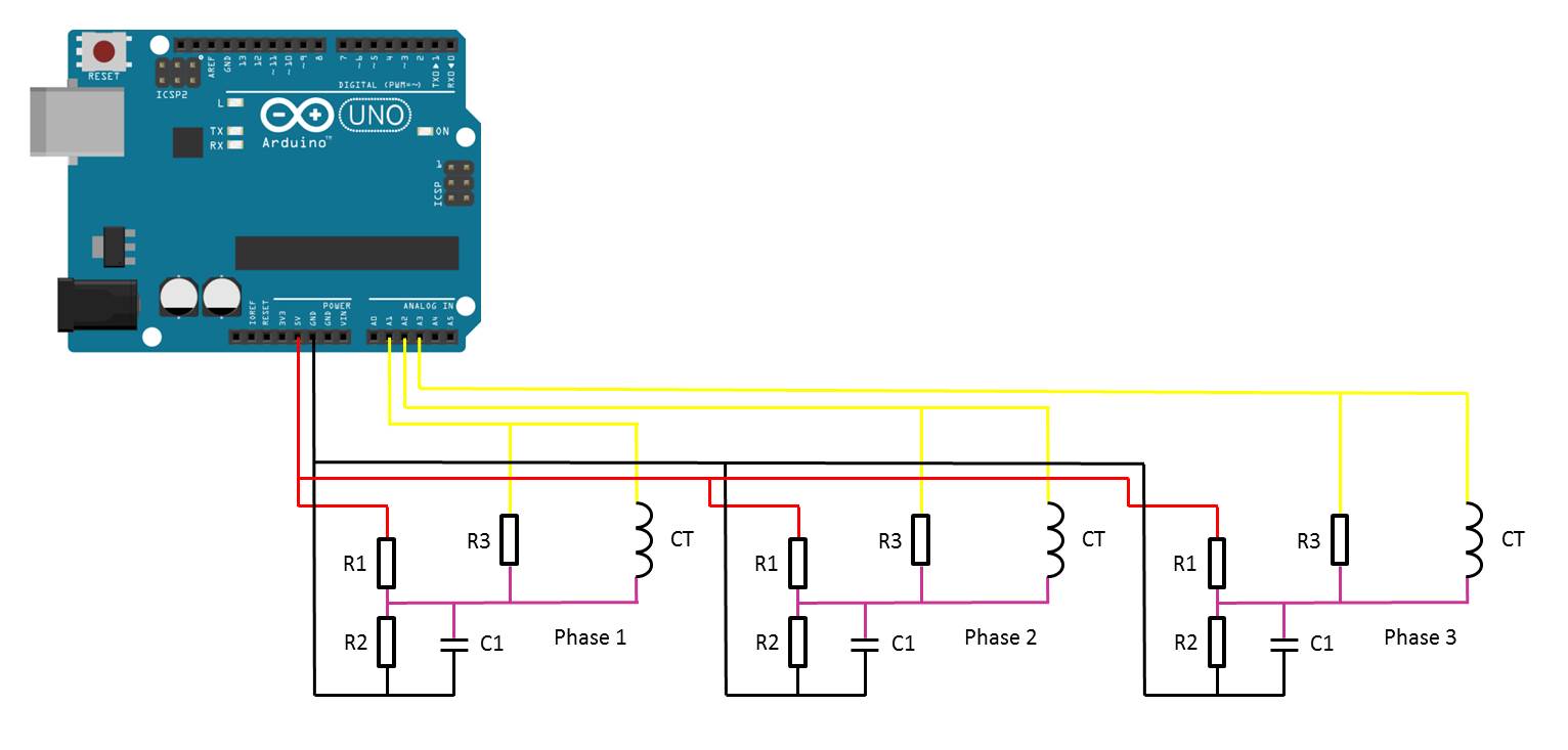
The basic circuit for the connection of the CTs to the Arduino is shown below:
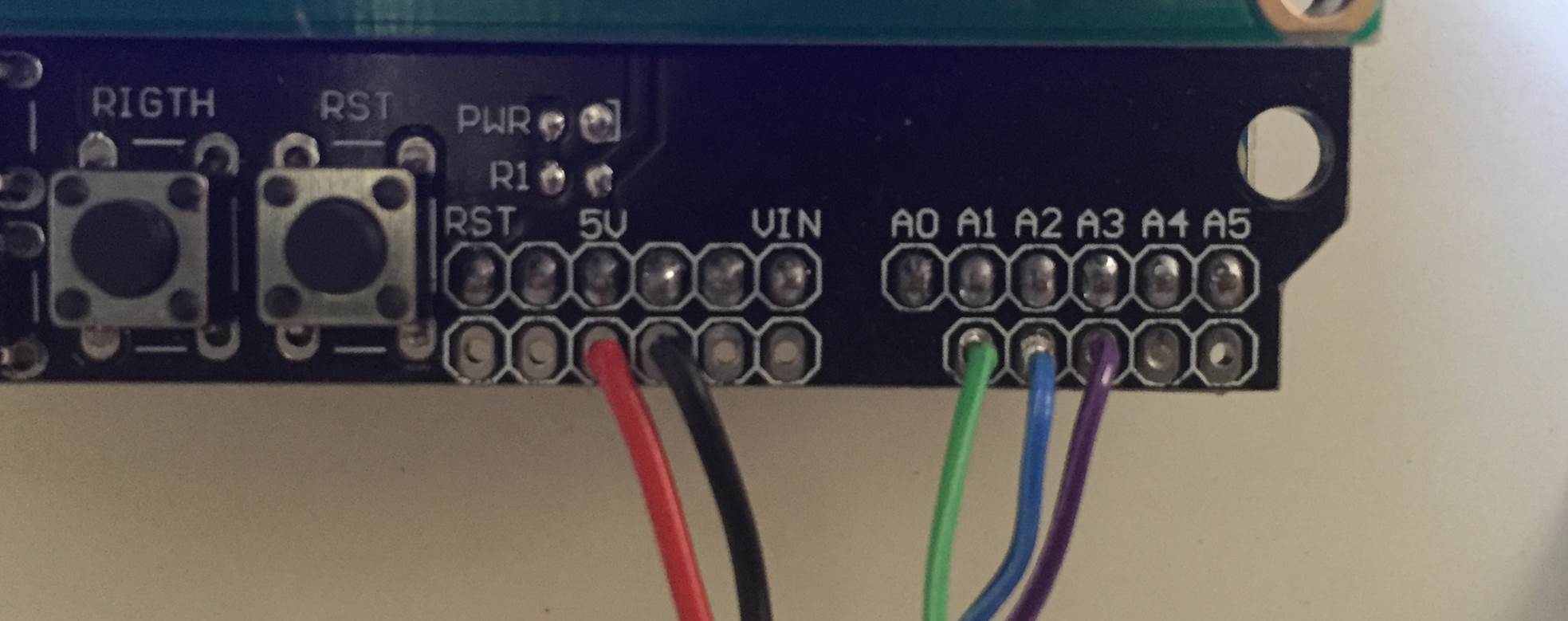
The LCD screen shield already picks up on the analogue inputs but only A0 is used by the shield for the button inputs. Simply solder the five leads from your current sensors onto the pin headers on the shield and use A1 to A3 as your sensor inputs as shown below.
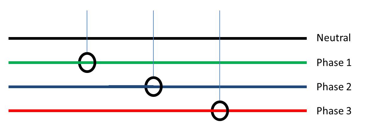
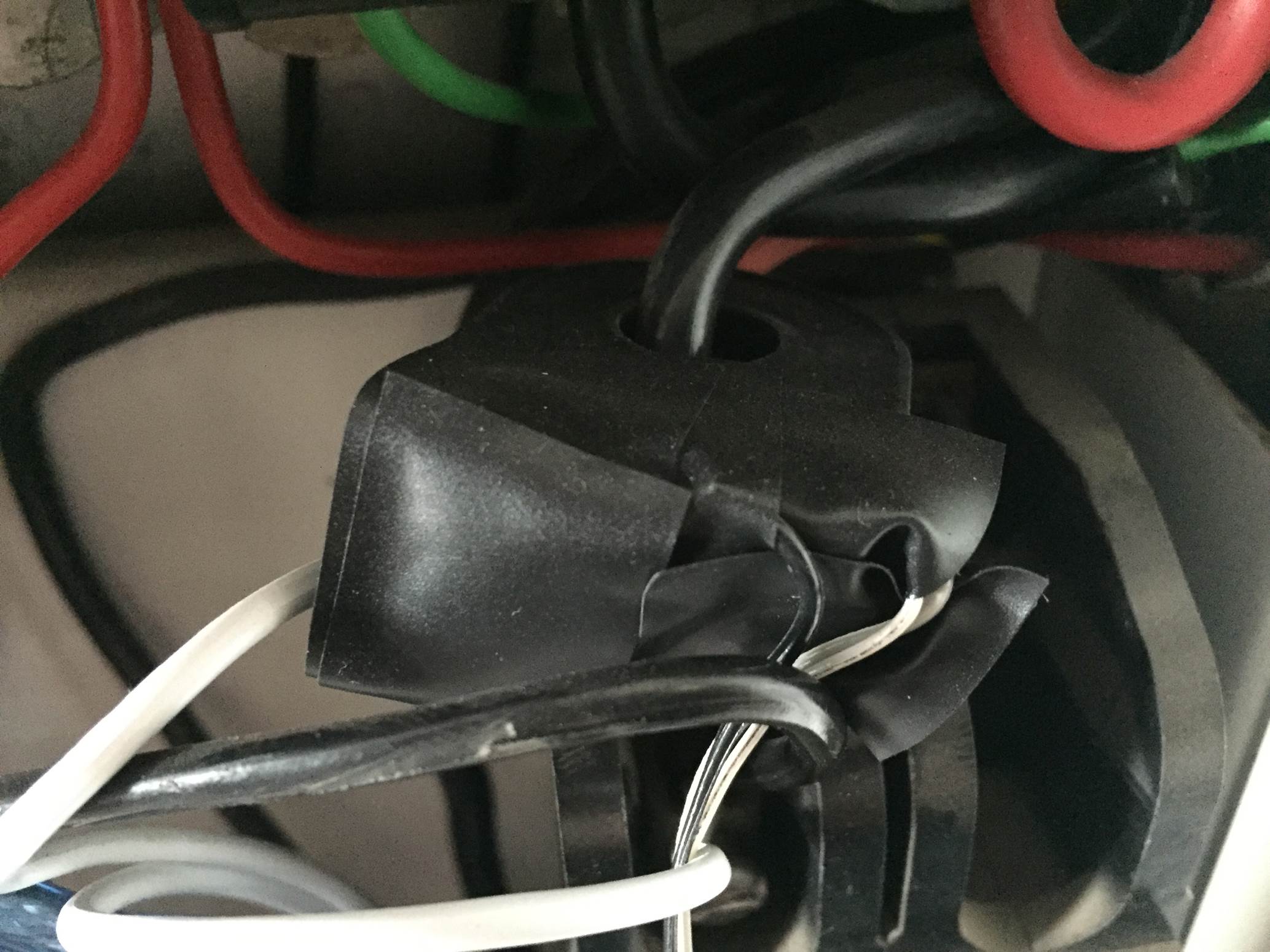
Once you have connected all of your components, you need to connect your sensors onto the supply you want to monitor. For connection to a typical 3 phase mains supply, connect one CT around each of the phases as shown below.
Each CT should only have one wire/phase running through its core.
NB – Be careful when connecting the CTs to your mains and make sure that the power to your board is switched off before doing anything in the mains box. Do not remove any wires or remove any screws before checking your local regulations with your local authority, you may require a certified electrician to install the CT for you.
Choosing Different Components
There are essentially four components which need to be chosen or correctly sized for you energy meter.
Choosing A Current Transformer
The first is the CT or current transformer. The one used here is the Talema AC1030 which can sense 30A nominal and 75A maximum current. At 220VAC, it can theoretically sense up to 16.5kW for short periods of time but it is sized to continuously sense 6.6kW which is suitable for a small household. To calculate how many amps yours needs to sense, take the maximum continuous power your are expecting to sense and divide that by your voltage (usually 110V or 220V depending on your country).
Sizing The Burden Resistor
Next you need to size your burden resistor R3, this converts your CT current into a voltage reference. Start by dividing your primary current (the maximum as used above) by your CT’s turns ratio (available on the data sheet). This should be around 500-5000 to 1. This article worked on 42A with a turns ratio 0f 1000:1 giving a secondary current of 0.042A or 42mA. Your analogue reference voltage to the Arduino is 2.5V so to determine the resistance you use R=V/I – R=2.5/0.042=59.5Ω. The closest standard resistor value is 56Ω, so this was used.
Here are some options on different CTs and their ideal burden resistors (in standard sizes):
Murata 56050C – 10A – 50:1 – 13Ω
Talema AS-103 – 15A – 300:1 – 51Ω
Talema AC-1020 – 20A – 1000:1 – 130Ω
Alttec L01-6215 – 30A – 1000:1 – 82Ω
Alttec L01-6216 – 40A – 1000:1 – 62Ω
Talema ACX-1050 – 50A – 2500:1 – 130Ω
Alttec L01-6218 – 60A – 1000:1 – 43Ω
Talema AC-1060 – 60A – 1000:1 – 43Ω
Alttec L01-6219 – 75A – 1000:1 – 33Ω
Alttec L01-6221 – 150A – 1000:1 – 18Ω
CTYRZCH SCT-013-000 – 100A – Built In Burden Resistor – Buy Here
The capacitor used is 10µF which should be sufficient for most CT ranges for household applications.
Finally you need two dividing resistors to get the 2.5V reference voltage from the Arduino. They must be the same value, so R1=R2 and we don’t need much current so this articles uses two 100K resistors.
Upload the Sketch
Now you can upload your sketch onto your Arduino, if you haven’t uploaded a sketch before then follow this guide on getting started.
//Michael Klements
//The DIY Life
//26 February 2017
#include <LiquidCrystal.h>
int currentPins[3] = {1,2,3}; //Assign phase CT inputs to analog pins
double calib[3] = {11.8337,11.8234,12.0325};
double kilos[3];
unsigned long startMillis[3];
unsigned long endMillis[3];
double RMSCurrent[3];
int RMSPower[3];
int peakPower[3];
LiquidCrystal lcd(8, 9, 4, 5, 6, 7); //Assign LCD screen pins, as per LCD shield requirements
void setup()
{
lcd.begin(16,2); // columns, rows. use 16,2 for a 16x2 LCD, etc.
lcd.clear();
lcd.setCursor(0,0); // set cursor to column 0, row 0 (the first row)
lcd.print("3 Phase");
lcd.setCursor(0,1);
lcd.print("Energy Meter");
delay(2000);
}
void readPhase () //Method to read information from CTs
{
for(int i=0;i<=2;i++)
{
int current = 0;
int maxCurrent = 0;
int minCurrent = 1000;
for (int j=0 ; j<=200 ; j++) //Monitors and logs the current input for 200 cycles to determine max and min current
{
current = analogRead(currentPins[i]); //Reads current input and records maximum and minimum current
if(current >= maxCurrent)
maxCurrent = current;
else if(current <= minCurrent)
minCurrent = current;
}
if (maxCurrent <= 517)
{
maxCurrent = 516;
}
RMSCurrent[i] = ((maxCurrent - 516)*0.707)/calib[i]; //Calculates RMS current based on maximum value and scales according to calibration
RMSPower[i] = 220*RMSCurrent[i]; //Calculates RMS Power Assuming Voltage 220VAC, change to 110VAC accordingly
if (RMSPower[i] > peakPower[i])
{
peakPower[i] = RMSPower[i];
}
endMillis[i]= millis();
unsigned long time = (endMillis[i] - startMillis[i]);
kilos[i] = kilos[i] + ((double)RMSPower[i] * ((double)time/60/60/1000000)); //Calculate kilowatt hours used
startMillis[i]= millis();
}
}
void loop() //Calls the methods to read values from CTs and changes display
{
readPhase();
displayKilowattHours ();
delay(3000);
readPhase();
displayCurrent ();
delay(3000);
readPhase();
displayRMSPower ();
delay(3000);
readPhase();
displayPeakPower ();
delay(3000);
}
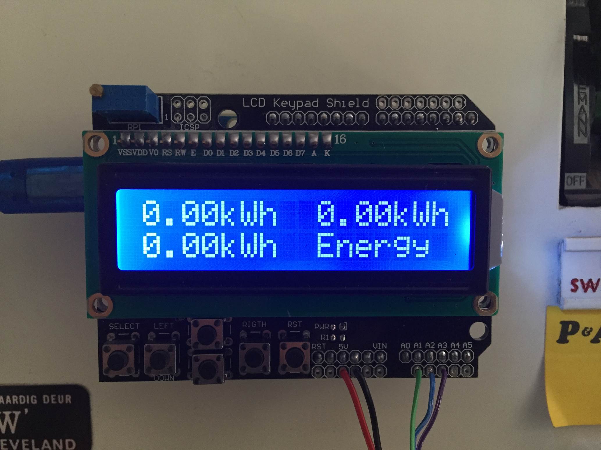
void displayKilowattHours () //Displays all kilowatt hours data
{
lcd.clear();
lcd.setCursor(0,0);
lcd.print(kilos[0]);
lcd.print("kWh");
lcd.setCursor(9,0);
lcd.print(kilos[1]);
lcd.print("kWh");
lcd.setCursor(0,1);
lcd.print(kilos[2]);
lcd.print("kWh");
lcd.setCursor(9,1);
lcd.print("Energy");
}
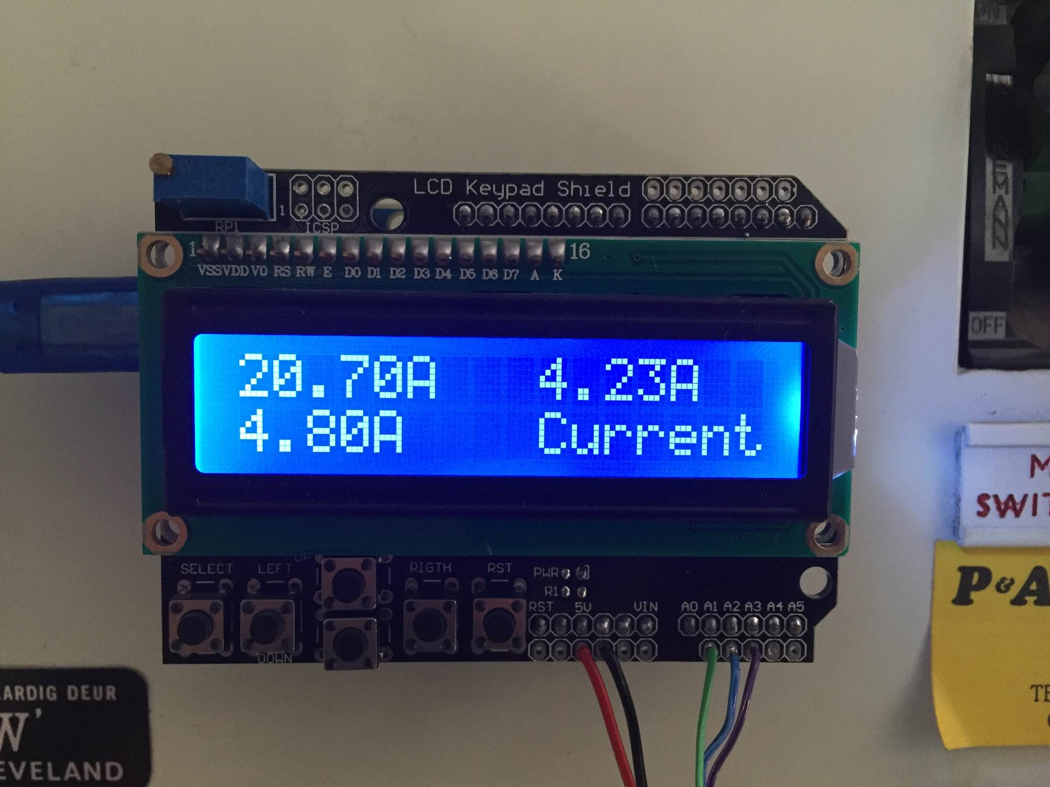
void displayCurrent () //Displays all current data
{
lcd.clear();
lcd.setCursor(0,0);
lcd.print(RMSCurrent[0]);
lcd.print("A");
lcd.setCursor(9,0);
lcd.print(RMSCurrent[1]);
lcd.print("A");
lcd.setCursor(0,1);
lcd.print(RMSCurrent[2]);
lcd.print("A");
lcd.setCursor(9,1);
lcd.print("Current");
}
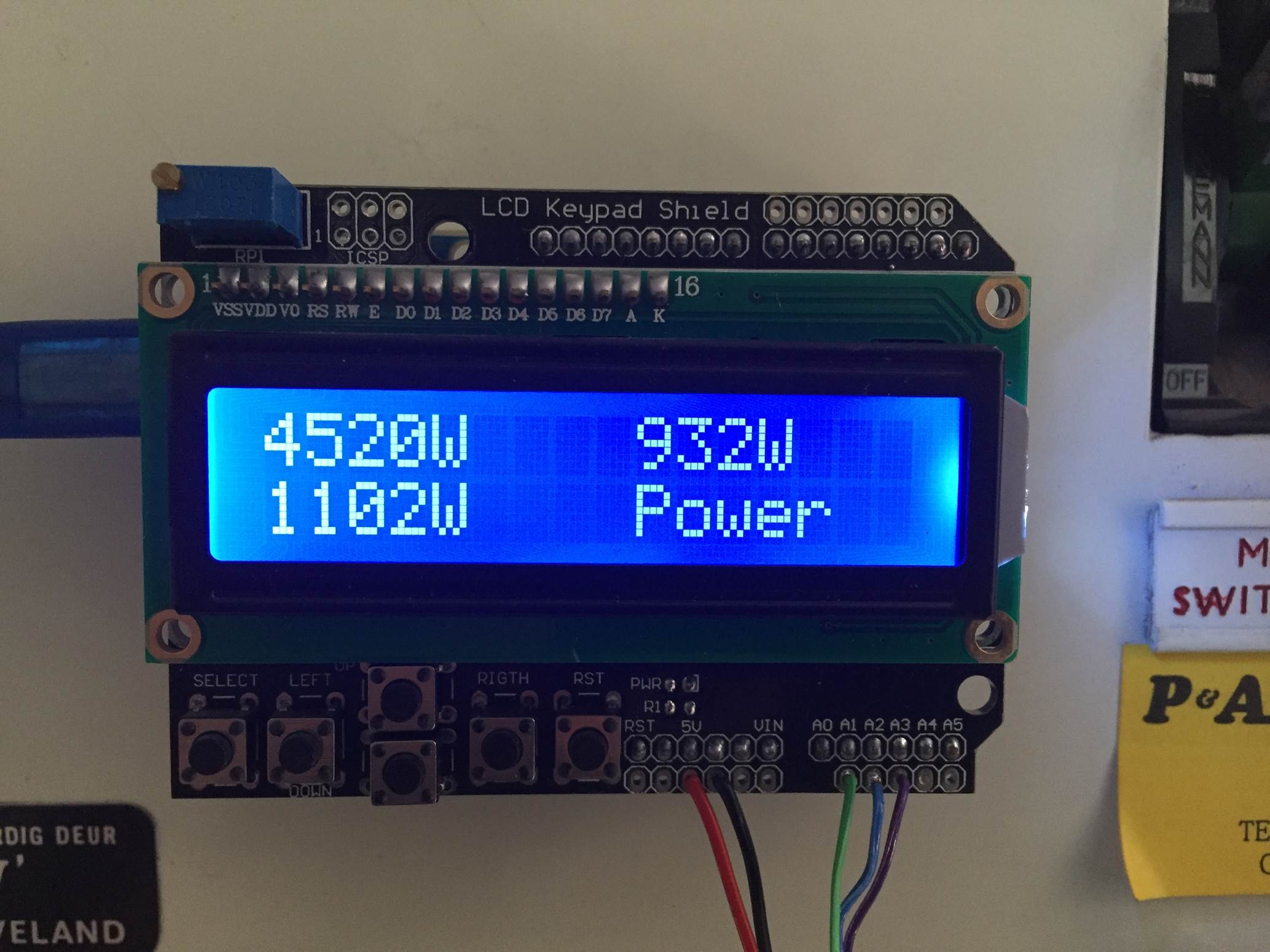
void displayRMSPower () //Displays all RMS power data
{
lcd.clear();
lcd.setCursor(0,0);
lcd.print(RMSPower[0]);
lcd.print("W");
lcd.setCursor(9,0);
lcd.print(RMSPower[1]);
lcd.print("W");
lcd.setCursor(0,1);
lcd.print(RMSPower[2]);
lcd.print("W");
lcd.setCursor(9,1);
lcd.print("Power");
}
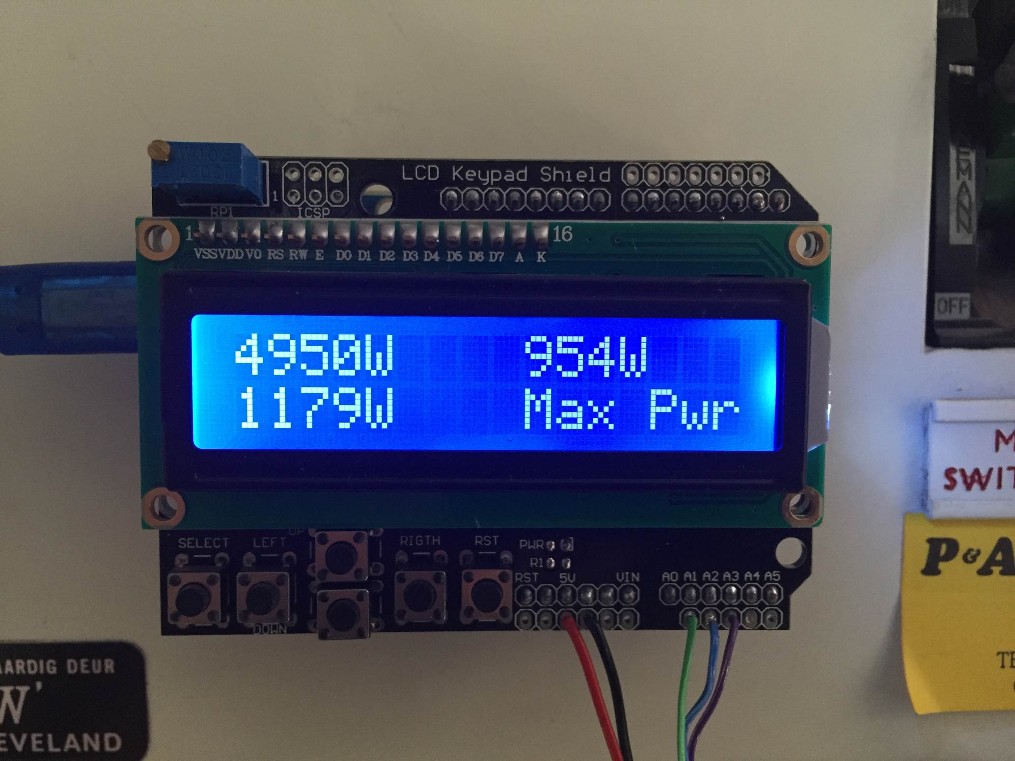
void displayPeakPower () //Displays all peak power data
{
lcd.clear();
lcd.setCursor(0,0);
lcd.print(peakPower[0]);
lcd.print("W");
lcd.setCursor(9,0);
lcd.print(peakPower[1]);
lcd.print("W");
lcd.setCursor(0,1);
lcd.print(peakPower[2]);
lcd.print("W");
lcd.setCursor(9,1);
lcd.print("Max Pwr");
}
Here is the link to download the 3 phase meter code.
Because your setup, CTs , resistors and input voltages may be different, there is a scaling factor in the sketch which you will need to change before you will get accurate results, see below for calibration. If your LCD is connected to the same pins as used here and your CT is connected to the same input pin, you should at least get the screens populated with some figures although these will most likely be incorrect and some may be negative.
This code, unlike our original simple Arduino energy meter’s code makes use of the millis() function to calculate the duration between cycles instead of relying on an estimate, this results in a slightly more accurate (about 0.5%) calculation. For those of you who have read that the millis() function goes into overflow after about 49 days, the code deals with the rollover automatically by making use of the unsigned long variable. For example, if the overflow happens at 10000, the start millis was 9987 and the end millis was 2031, the difference would be 2031-9987=-7956 but the value can’t be negative as it is unsigned so it becomes -7956+10000=2044 which is the correct duration.
Calibrate the Current Reading
As mentioned above, because your setup, CTs , resistors and input voltages may be different, there is a scaling factor in the sketch for each CT which you will need to change before you will get accurate results.
To calibrate your energy meter, your need to be sure that the current that your meter says is being drawn on each phase is what you expect is actually being drawn. In order to do this accurately, you need to find a calibrated load. These are not easy to come by in a normal household so you will need to find something which uses an established and consistent amount of power. I used a couple of incandescent light bulbs and spot lights, these come in a range of sizes and their consumption is fairly close to what is stated on the label, ie a 100W light bulb uses very close to 100W of real power as it is almost entirely a purely resistive load.
Plug in a small light bulb (100W or so) on each phase and see what load is displayed. You will now need to adjust the scaling factors defined in line 8 accordingly:
double calib[3] = {11.8337,11.8234,12.0325}
In this case they were 11.8337 for phase 1, 11.8234 for phase 2 and 12.0325 for phase 3. They may be higher or lower depending on your application. Either use linear scaling to calculate this figure or, if you’re not good with math, play around with different values until the load you have plugged in is shown on the energy meter’s screen.
The Energy Meter In Operation
Once you have you energy meter calibrated and the scaling factors have been uploaded onto the Ardunio, your meter should be ready to connect and leave to monitor your energy consumption.
Upon startup, you’ll see a 3 Phase Energy Meter screen followed by cycling through the current, power, maximum power and kilowatt hours consumed screens. In each case, the top line displays phase 1 and phase 2’s measurements and the bottom line displays phase 3’s measurements.
Current Screen
Power Screen
Maximum Power Screen
Energy Consumption Screen
Video Of The Energy Meter In Operation
How did this project go for you? What have you used it to monitor? If you have any questions or would like to share your build of this three-phase energy meter, please post a comment below or send a mail using the contact form.
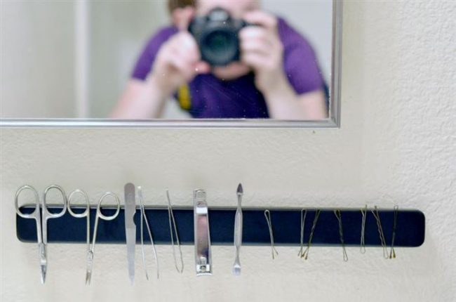
Every now and again your find an extraordinary use for a ordinary household object. To some people these out of the box ideas come naturally, to others, we have to read lists like these. Here are some of our favorite ways to use common household items in totally different ways.
Aluminium foil makes a fantastic cover for your door hardware when painting and makes a great scrubbing pad for cleaning glassware.
Got a wet towel or clothes from your vacation which you need to pack without your whole bag becoming smelly. Wrap a bar of soap up in the towel to prevent the unpleasant smell.
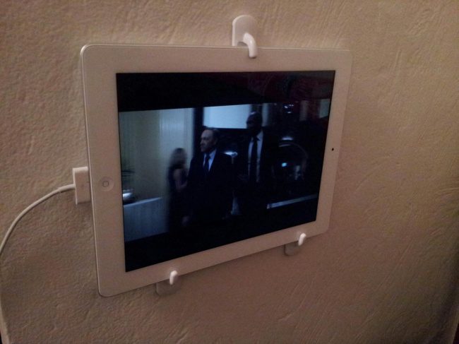
Stick a couple of towel hooks onto the wall in your kitchen, bedroom or study to make a neat tablet holder. Now you can watch series or movies while you do your chores.
Cleaning small window blinds is not difficult to do as long as you know how. I’m sure you’ve tried wiping each individual slat down by hand or you’ve bought one of those blind cleaning tools with five or six fluffy prongs to clean multiple slats at once. They work well on big blinds but not so much for the smaller ones.
Cleaning them is actually quite easy and doesn’t take up a whole lot of time, the secret is to take them down first and this is a whole lot easier than it sounds.
How To Clean Your Blinds
Fill your bathtub up halfway with warm water, add a half cup of dish soap to the running water so that it mixes in well. If you don’t have dish soap, you can also use ammonia.
Use the cord to pull the blinds up all the way. Most of these blinds are secured to the clips holding them up with a simple lever, turn the lever or pull it out towards you and the blind is released. To put it back simply seat the blind on the bracket and turn the lever the other way or push it away from you and towards the blind, it really is that simple.
Once the blind is off the wall, release the cord a bit so that there is some space between the slats. Adjust the rod so that the slats are slightly tilted and this will assist you with cleaning them.
Lower the blind into the warm water in the bathtub, being careful not to bend or crimp and of the slats.
Let the blinds soak for about fifteen minutes to loosen the dirt and break down any grease buildup. Now use a light sponge to gently wipe the slats down, the dirt should come away easily.
Once the blind is almost entirely clean, drain the water from the tub and now use the handheld shower attachment or shower to rinse the soap from the blind and dislodge and further dirt that is difficult to reach.
Shake the blinds gently to remove any excess water, then hand dry them with a towel. If you have a sunny spot on the floor in your home somewhere then place the blind in the sun for an hour or so to dry off completely.
Rehang the blind securely in the window. Use the cord to let the blind down the whole way. Separate any slats which are stuck together and make sure that they are all facing the same way. The remaining water should evaporate within a half hour and your blinds will be as good as new.
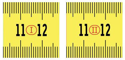
We’re pretty sure most people know how to use a measuring tape, but what you probably don’t know is what all of the different markings mean. Have you noticed the roman numerals and black diamonds?
Metric & Imperial Markings
If you live outside of the UK, chances are your measuring tape will have either metric or imperial measurement grades and units on it. In the UK however it is quite common to get measuring tapes with both as the European Union has enforced use of the metric system however many tradesman still prefer to use imperial units.
How Accurate Is Your Measuring Tape?
Pull out your tape and in the first few centimeters or inches there should be a roman numeral printed inside a rectangle or circle, this numeral refers to the accuracy of the measuring tape.
There are generally four grades of accuracy with Class 1 or I being the most accurate and and Class 4 or IV being the least accurate. If you’ve bought a cheap or unclassified tape, it won’t have any Class markings on it which simply means that is has not been tested and therefore doesn’t guarantee any level of accuracy.
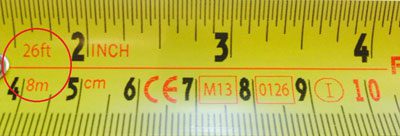
The Length
The total length of your tape measure is generally printed in red somewhere right near the tip of the tape in red. If you have a tape measure with both imperial and metric units, the length of both with be shown next to their respective scales.
Now Here Are The Less Known Tape Measure Markings
Black Diamonds
You may have noticed that there are little black diamonds every so often down the length of your tape measure. They are used by tradesman as stud and joist marks, stud marks typically occur at 16″ intervals and joist marks at 19.2″ intervals. These may seem like strange denominations but they are derived from the fact that most American building materials come in 8ft lengths, 8ft divided 5 times gives you the perfect width for joists which happens to be 19.2″ as indicated on the tape.
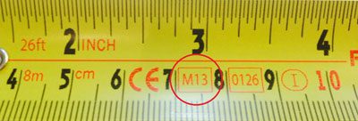
Year Of Manufacture
The last two digits of the year of manufacture is often written alongside an M in a red or black rectangle. The year of manufacture is printed onto most modern tapes as a means to identify that it was manufactured to conform to a certain set of regulations applicable at that time.
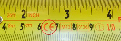
CE Marking
If your tape was bought in Europe or manufactured with resale within the European Union in mind then it should have a CE printed on it, this means that it conforms to all of the European Union regulations applicable to it during the time of manufacture. It doesn’t mean it was manufactured in the EU but it does suggest that it was intended for resale there.
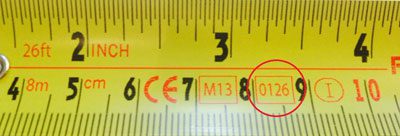
Testing Body
Somewhere near the year of manufacture, there may be another four digit number within a rectangle, this number relates to the agency responsible for the issuing of the certification. The codes can generally be looked up online and correspond to a registered institution or laboratory.
We all know the struggle, you get out of the shower and need to use the mirror and its covered in fog, wiping it with a towel leaves it full of streaks so you’re forced to open a window and allow it to dry off properly before you can see anything. A friend of mine one day told me about a trick they had tried to stop their bathroom mirrors from fogging up. The trick sounded too straight forward, and quite frankly like it wouldn’t work, so I pretty much forgot about it until a couple of months later. I got out of the shower, on a particularly frustrating day, to a foggy mirror and I remembered what my friend had told me, so I decided to give it a try – the next day of course as the trick only works when the mirror is dry to start with.
Stop Your Bathroom Mirrors From Fogging Up
All you need for this trick is a regular bar of soap and a soft dry cloth. Take the bar of soap and gently rub it onto the mirror’s glass. You only need to rub the bar of soap very lightly, it doesn’t need to completely cover the glass as the next step will take care of that. When you’re done, you should have a fairly hazy patch of glass in the middle of your mirror but there shouldn’t be any chunks or thick streaks of soap on it.
Now take a soft cotton or microfiber cloth and buff the soap residue off of the mirror so that it is shiny again. You’ll now appreciate not having put too much soap on in the first step! If you are struggling to get it off, you can add a tiny spray of glass cleaner but too much will remove all of the soap residue and prevent the trick from working.
When you are done, the mirror should look as it was before you added the soap, there shouldn’t be any haze or soap lines left on the glass. There will however be a thin, invisible film from the soap bar left behind which will prevent the glass from fogging up in the future.
Next time you take a shower, you’ll be greeted with a fog free mirror when you’re done.
Now you just have to remember to add some soap to the drying process next time you give your mirror a wipe down and your mirror will stay fog free!
Have you finished dusting and cleaning your home only to notice a layer has formed again after a few hours? It almost seems impossible to get rid of the dust that has accumulated in your home! Fortunately, it’s not that difficult to do, you just need to make sure you’re cleaning the right things to get rid of as much dust as possible with each clean.
Wet wipes quickly capture the dirt and keep it trapped so there is less risk of the dust rising into the air again. By using a wet cloth and rinsing it out in a bucket, by the third or fourth rinse you start rubbing the dust trapped in the water back onto the furniture, it dries and again rises into the air. Use a new wipe for each large item of furniture once a week for the best results. You could even try making your own wet wipes.
Dust All Of Your Furniture
Dust settles on everything in your home and so you need to dust everything as well. Just dusting the surfaces you use often or which look dirty means you’re leaving dust around your home which can easily be spread. Next time you’re dusting, remember to clean your mirrors, television, picture frames and decor.
To make extra sure you’re getting all of the dust, vacuum your couch or sofa once a week as well. It settles on the fabric and is thrown up into the air every time somebody sits down or stands up.
Wash Your Curtains
You should wash all of your curtains in your home at least once a season. Being so close to the windows and draughts, they accumulate a lot of dust along the seams and in the folds which is then blown into your home whenever you open and close the curtains.
Brush Dust From The Corners
Get yourself a soft bristled dusting brush and start using it to brush dust out of the corners and small gaps. You’ll be surprised at how much accumulates in the spaces you can’t reach with a cloth or wet wipe.
Wipe Down Your Plants
Plants are often put in a corner, watered and left alone. No one ever thinks to clean them, they clean themselves right? Actually they don’t, plants stay clean outdoors because of the rain and wind, when you’ve put them indoors they will need a wipe down every now and again. Wipe the leaves with a damp cloth from time to time to keep them clean.
That’s it, just by doing these five things, your home will already be a whole lot cleaner and you’ll notice a drastic decrease in the amount of dust which builds up.
Traditional soldering irons use a heated tip to melt solder in order to make electrical joints, while this works well when you have a mains outlet around, its not that practical when you’re out in the field. Anyone who’s done anything RC will know the frustration involved in a joint coming loose or a wire breaking off in the middle of a day out. You can buy a couple of different models of cordless soldering irons online but the main drawbacks are either lack of power or short battery life, the cold heat soldering iron addresses both of these problems. If anything it is perhaps a bit too hot and since it is only on instantaneously, you can make loads of joints (100+) before the battery runs flat.
The cold heat soldering iron works by essentially “short circuiting” the battery across the solder joint, the solder acts as a resistor, heats up really quickly and melts to form the joint as in the normal soldering process. The concept is similar to a traditional soldering iron in the way the tip is heated although in this case, the heated part is the actual solder and not a soldering tip.
What’s even better about this project is that it can be built using things lying around at home, there really is nothing complicated about it.
What You Need To Build A Cold Heat Soldering Iron
A Scrap Piece Of Copper, Aluminium Or Brass Tubing (8cm/3″)
A Thin Piece Of Scrap Glass (Or Mica, Plexiglass, Acrylic etc)
A Short Length Of Ripcord Or Any 2 Strand Wire
Some Pencil Lead (Graphite) Refills
Heat Shrink Tubing or Insulation Tape
LiPo Battery Plug To Match Your Battery
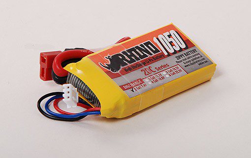
A 1000mAh 2 Cell Lipo Battery (Or Similar Capacity 2 Cell)
A Piece of Wood, Pen Or Dowel For The Handle – Alternately, Below Are Plans To 3D Print A Case For The Tip & Battery
Making Your Cordless Cold Heat Soldering Iron
Making The Soldering Iron Tip
The tip is the most important part of your soldering iron so it pays off to take some extra time to get it right.
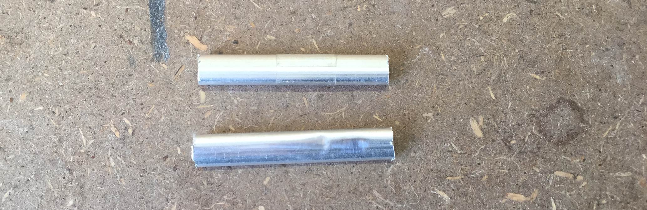
Start off by cutting your scrap piece of tubing into two equal sections of about 4cm or 1 1/2″ long, this doesn’t need to be all that accurate but it needs to be long enough to adequately support the pencil leads and absorb some of the excess heat created when soldering.
Now strip the plastic insulation off of the ends of your ripcord to expose the wire, the exposed wire should extend about halfway into the tubes with the edge of the insulation up against the tube ends.
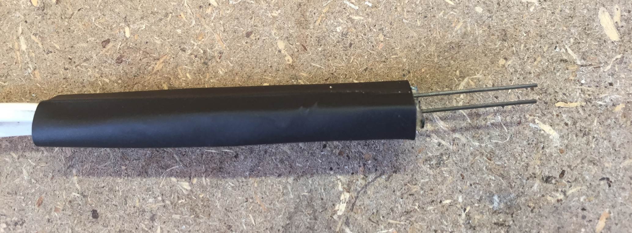
Push each wire into the tube and then use a hammer or a pliers to squash the tube flat over the wire. Flatten the whole length of both tubes, these are going to be your contacts onto the pencil leads.
Now cut a strip of glass from your sheet of glass, the piece needs to be the same width and length as the flat tubes. In this case, the flattened tubes were about 1cm (2/5″) wide. Use a glass cutter to score the glass and then break off a strip of the correct width before breaking it to the correct length.
The glass strip should be a similar size to the flattened tube contacts when you are done.
Before assembling the tip, you need to score the tubing so that the pencil leads are held firmly and in the centre of the tube contacts. Use a pair of side cutters, a craft knife or a Dremel to cut or score a line down the centre of each contact as shown below, the line doesn’t need to go the full way down the length of the contact.
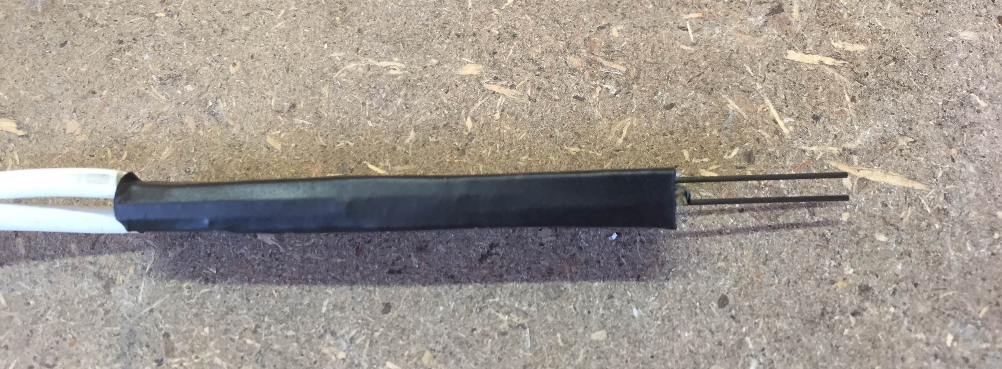
Assemble the tip by putting the glass strip between the two contacts with the score marks facing inwards towards the glass. Insert the pencil leads between the contacts and the glass, lining them up with the score marks, and then wrap the tip up with insulation tape or put a piece of heat shrink tubing around it.
Once you are happy with the position of all of the components and the alignment of the pencil lead, heat up the heat shrink tubing with a lighter, heat gun or blow torch briefly to shrink it together and lock the pieces in place.
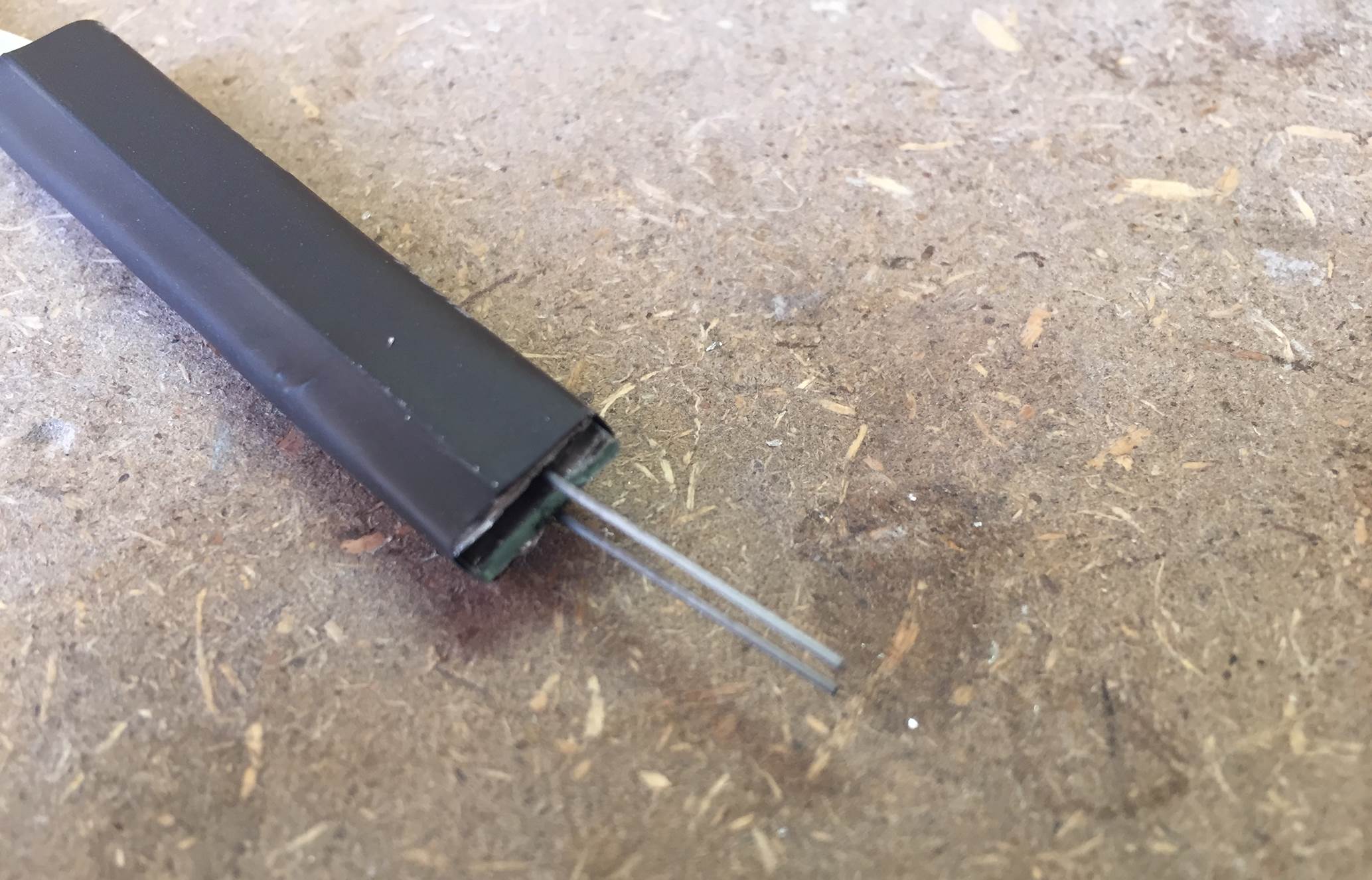
The pencil leads should be close together but not touching each other when you are done. You will now need to be very careful when handling your soldering iron tip as the slightest bump will break the pencil leads, they are really fragile.
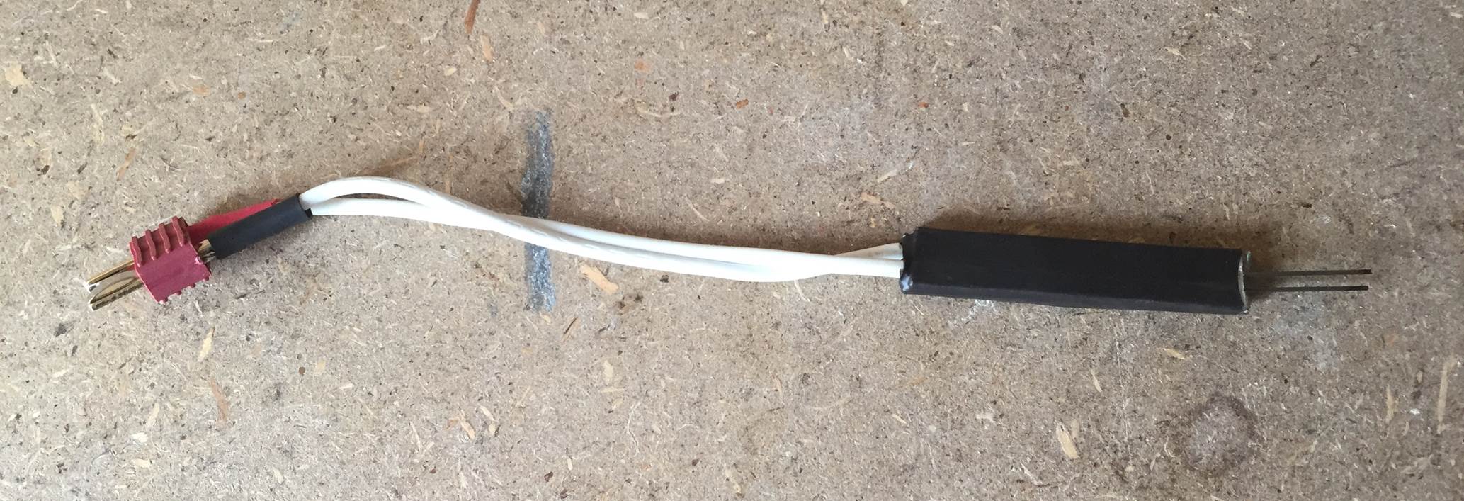
On the other end of the ripcord lead, you need to solar on your battery plug. The polarity (positive + and negative -) of the battery plug don’t matter for this tip so you can solder either lead onto either of the plug terminals.
The tip and electrical connections are now completed.
Testing The Cold Heat Soldering Iron Tip
Once you have completed your tip, you should probably test it and check that the connections are made correctly before you go through the effort of mounting it onto a handle or inside a case.
To test the tip, make sure that the pencil leads are not touching each other or anything conductive, they should preferably be raised a little off the counter or work surface. Now plug the tip’s lead into your charged LiPo battery.
With the battery plugged in, take a piece of thin strand solder and touch it against the two pencil leads simultaneously. It should smoke a little bit and then the solder will begin to melt. A little spark or the tips of the pencil leads turning bright orange is quite normal, just don’t allow the whole pencil lead to turn orange.
Shown in the video below is our test of the tip, we plugged the tip into a power monitor to check the voltage and maximum current when soldering to ensure that the current was not exceeding the batteries limit.
The battery voltage was 8.33V which is normal for a fully charged 2 cell Lipo and the maximum current drawn to melt the solder was 5.30A which is well below the batteries 20A limit. With a 1000mAh battery, you should get about 11 minutes of soldering before the battery needs charging. That’s 11 minutes of actual contact between the two pencil leads, which is a lot of soldering time, around 130 joints if each takes 5 seconds or so.
The power meter used to take these measurements can be found through this link.
Mounting The Soldering Iron Tip
Once you are happy with how your tip works, you can mount it onto a handle or rod so that it’s easier to use. A round wooden dowel works well as a handle and is relatively inexpensive. Tape the tip to one end and the battery to the other end, you’ll now have a neat pencil like portable soldering iron.
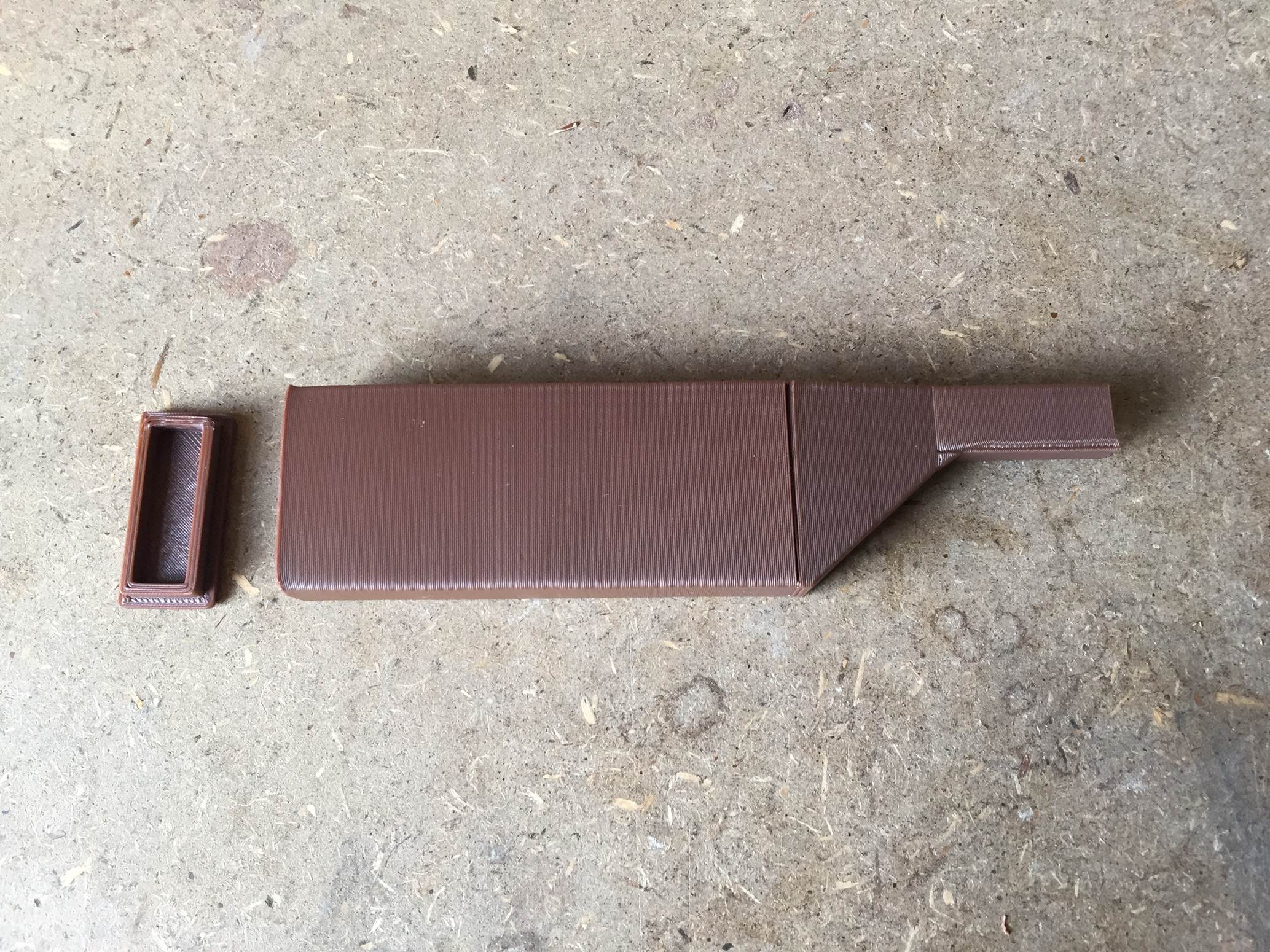
We decided to take it one step further and 3D print a case to house the tip and the battery. The case is printed in two parts, one is the actual case in which the tip is mounted and the battery fits into and the other is the end cap to close off the battery compartment.
The case was designed for a 0.4mm nozzle printer but it can be printed with any printer with a suitable build volume. The material used was HIPS with a nozzle temperature of 225°C (437°F) and a bed temperature of 95°C (203°F).
Here is a timelapse video of the case being printed:
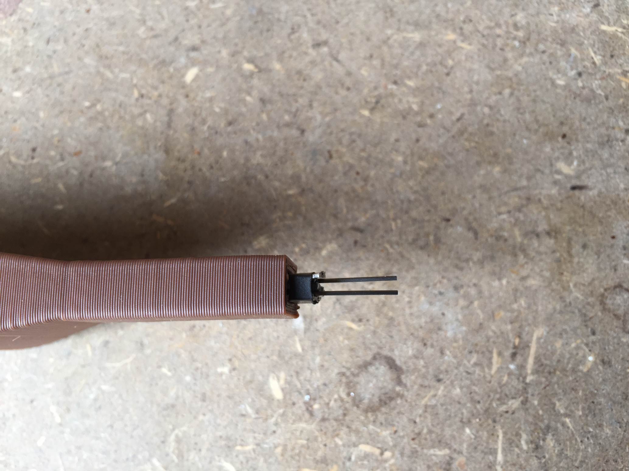
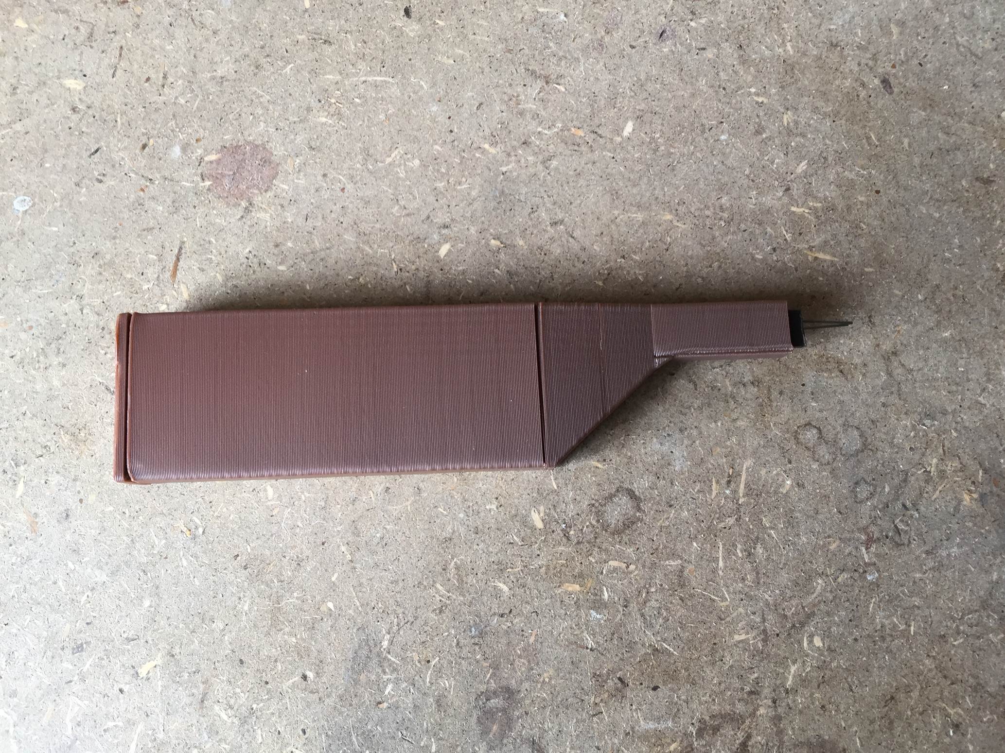
Once you have printed both pieces of the soldering iron case, the tip needs to be installed. The tip fits tightly into the front of the case, you may need to remove the pencil leads to push it into the case and then replace them afterwards.
The complete soldering iron.
Using The Soldering Iron
Although the battery is effectively not in circuit when the soldering iron is not in use, you should always keep the battery unplugged when you are not using it to prevent something short circuiting the tip. A stray tool or screw in your toolbox may fall across the pencil leads and could cause a fire.
You can use any two cell battery you already have for your RC hobbies or whatever is available from your local RC store, it doesn’t need to be a high spec LiPo battery. A two cell battery has enough voltage and 1000mAh is enough capacity for a fair bit of soldering before it needs to be charged. To get more soldering time out of your soldering iron, use a battery with a larger capacity – 1500mAh or 2000mAh. We don’t recommend increasing the voltage (number of cells) above two, this design works quite well between 5V and 10V so a 2 cell LiPo is perfect.
To solder a joint, simply hold the soldering iron in one hand as you do with a regular soldering iron and then solder in another hand, gently touch the tip onto the joint and bridge the two pencil leads with the solder wire. The solder will melt and the joint will be formed. Do not press down on the pencil leads as they are extremely fragile and will break. It may be tempting to push down harder if the tip doesn’t heat up at first, rather move the solder wire around to a better angle.
Here is a video of two joints being made:
Some General Usage Tips
Don’t attempt to solder any sensitive electronic circuitry with this soldering iron. There is a voltage difference across the tip which may damage sensitive components.
Remember not to over discharge your LiPo batteries, use a battery monitor to alert you when the battery is running low.
Keep the tip away from anything conductive when the battery is plugged in and always unplug the battery during transport.
Work quickly, once the joint is hot, push the solder you need into the joint and stop quickly. The tips of the pencil leads may start glowing but don’t let the whole lead heat up, it will start to damage the heat shrink or insulation tape you used to hold the tip together.
Don’t press down on the tip, the pencil leads are really fragile and will break if any pressure is applied to them. Rather move the solder around until it touches both ends of the pencil lead, this will cause it to melt.
Try making a cap to protect the pencil leads when you’re transporting the soldering iron, this way you can leave it loose in your toolbox.
You could use an RC brushed ESC to vary the voltage and current supplied to the tip for smaller or larger jobs, a servo tested could be used to give the ESC the reference signal.
Share This Guide:
Have you made your own cold heat soldering iron? Let us know in the comments section below, we would love to hear your tips and tricks.
Motivation can be difficult to find. We often know what our goals are but struggle to stay motivated in order to reach them and we certainly aren’t going to get there by hoping. We need action!
Not too many people want to go to the gym and workout everyday yet most people want to be fit and healthy, motivation is what we need to bridge the gap and get us there. Once you have figured out where you want to be, do these 7 things daily in order to find the fuel to get you there.
Set Short Term Goals
Your goals are most likely not going to be achieved in a week or even a month and it may become difficult to find motivation during the middle portion of your goal period. Break your goals up into little chunks and you’ll be much more likely to achieve them. For example, instead of saying you’d like to loose 20kg or 45lbs in the next 6 months, rather set your goal on loosing 3.5kg or 7.5lbs a month for the next 6 months. Each month you reach your weight loss goal will give you the required motivation to get through the next month.
Create Reminders
Reminder can be in the form of alerts on your cellphone or physical sticky notes. Either way, use these reminders to keep your goals in mind throughout the day, we often need the extra help in the beginning until it becomes a habit. For example, if you’ve decided you need to drink more water throughout the day, set reminders for every two hours so you don’t find yourself leaving work and realising that the last time you drank water was with lunch.
If you need to get your life more organised in order to meet your goals, have a look at our top 5 apps to get organised with.
Meetup With Friends And Family
Never underestimate how much motivation friends and family can provide for you, especially if you are an extrovert. Bringing a close friend or family member into your goal can provide you the extra motivation you need on the bad days.
Stay Motivated With Music
If you struggle with the daily tasks required to achieve your long term goals, music may help you to set the tone. Create a slow and classic playlist to wind down and de-stress or a rock playlists to wake up and keep moving. A good playlist is especially useful for tasks which take time, like cleaning up the house, going to gym or just finding the time to relax.
Keep An Eye On Your Progress
Keep a journal or document your progress and remember to keep looking back on the progress you’ve made. When you see how far you’ve come, you’ll find it easier to stay motivated to continue moving towards your goal, however far it may seem.
Update Your Wardrobe
How you dress is often reflected in the work you do and it can give you the confidence you need to pursue your goals. It doesn’t even need to be a complete outfit, just a need item of clothing or accessory can go a long way. You could even reward yourself for achieving your daily steps towards your goal, put a portion of money away each day you are able to work towards your goal. Once you reach your goal, you’ll be able to reward yourself with a new watch, accessory, item of jewelry or gadget.
Try To Keep It Fun
Always try and add an element of fun to your goals and enjoy the work involved in reaching them. When we lose the enjoyment, we often give up on the goal itself. You need to get creative, a funky water bottle for your drink more water goal, a new fitness watch for your weight loss, having a friend join you running, small things help to bring the fun and excitement back into a task and stay motivated.
Keeping your home clutter free is a good way to stay motivated, you’ll spend less time worrying about things or trying to find things and have more time to do the things you love and to achieve your goals.
How do you stay motivated in your day to day life? Share your advice, tips and tricks with us in the comments section below.