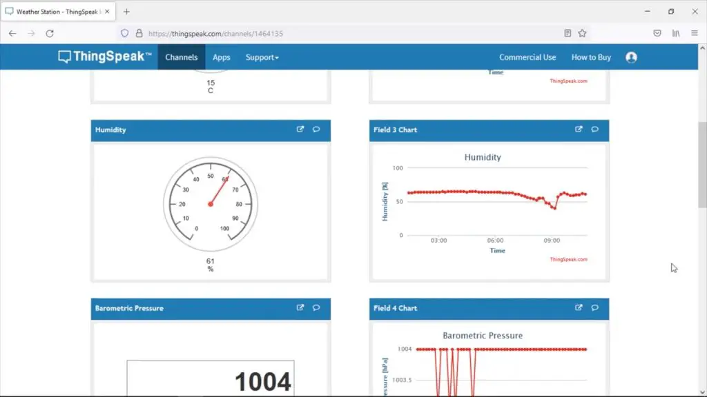
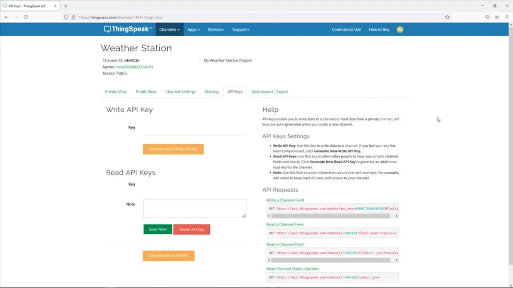
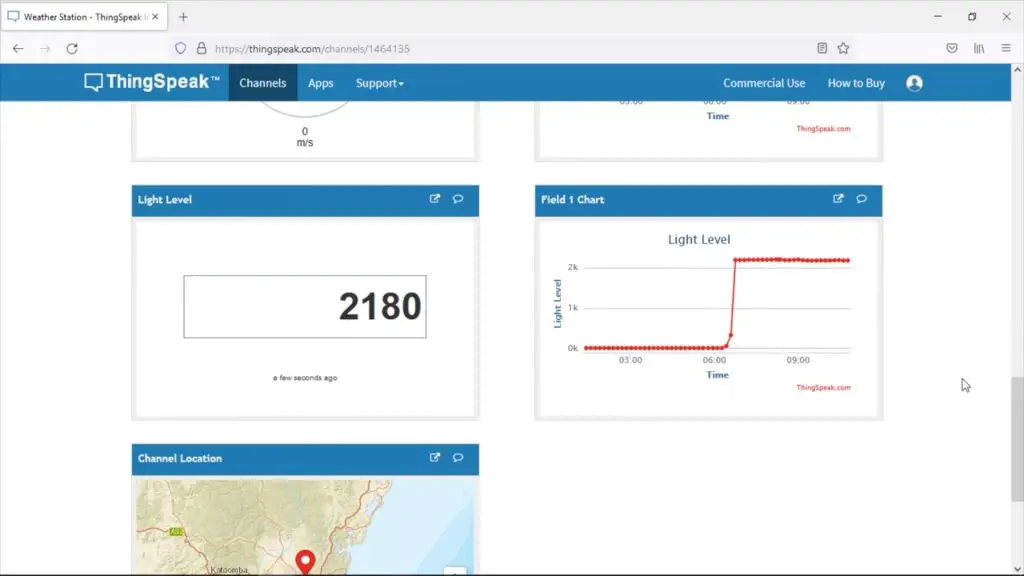
Today we’re going to be making some upgrades to my previously built IoT weather station using suggestions that you guys made in the comments section. We’ll see how well the weather station performs after the upgrades and I’ve included a link to the public Thingspeak channel, so you can have a look at the most recently recorded data.
Here’s my video of the upgrades I’ve made, read on for the written guide:
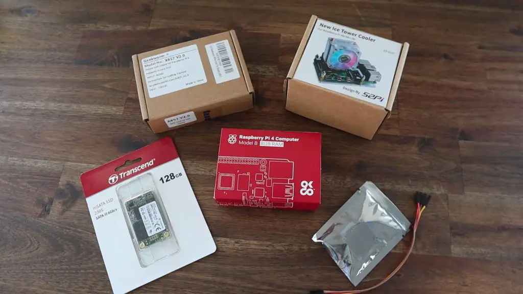
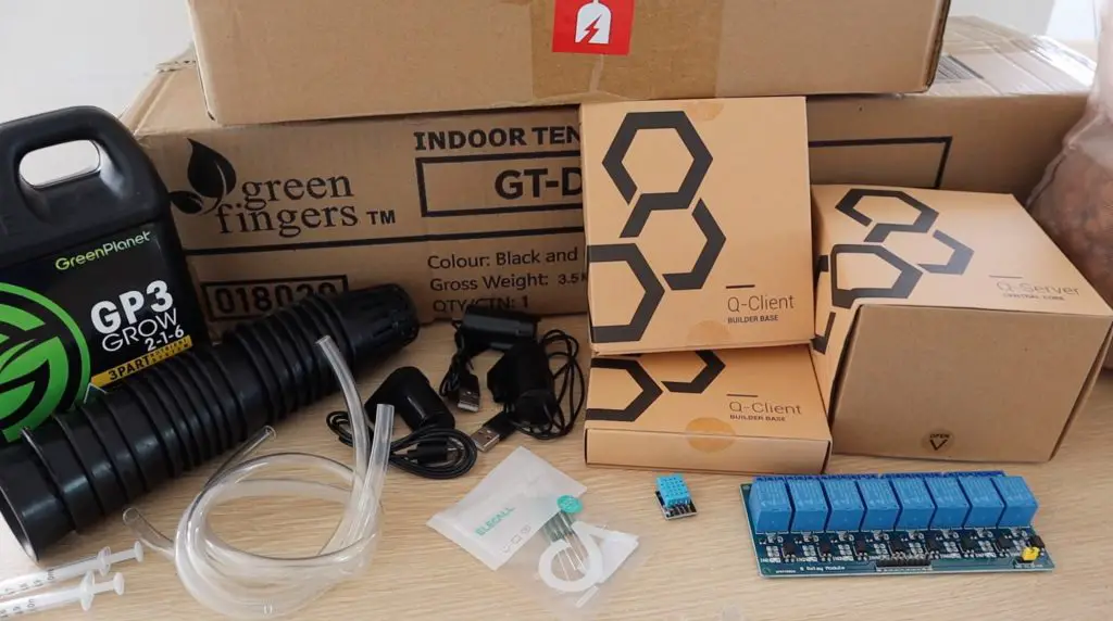
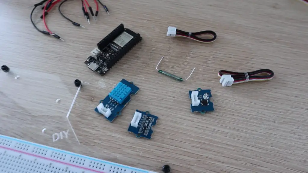
Upgrade Components Needed
In addition to the components that we’re going to re-use from the last project, you’ll need the following:
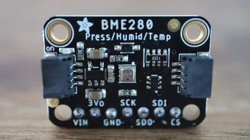
- BME280 Sensor – Buy Here
- Allegro A3213 Hall Effect Sensor (Link is for A3144, Amazon don’t have A3213) – Buy Here
- 3000mAh LiPo Battery – Buy Here
- 5V 1A Solar Panel (Similar Specs) – Buy Here
- Solar Power Management Board – Buy Here
- Ribbon Cable – Buy Here
- Header Pins – Buy Here
- Button Head Screws – Buy Here
I also use the following tools and equipment in this build:
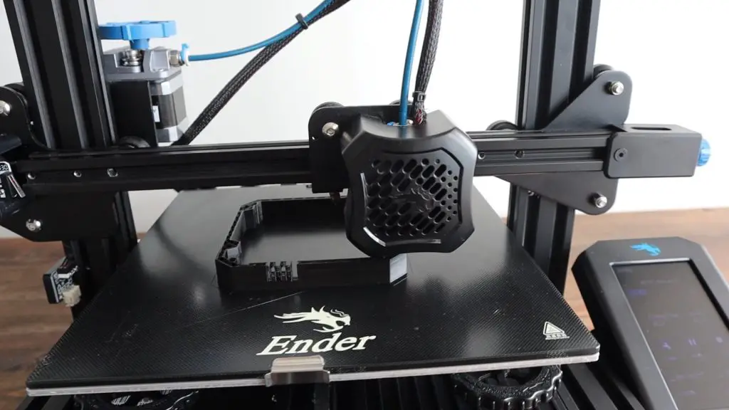
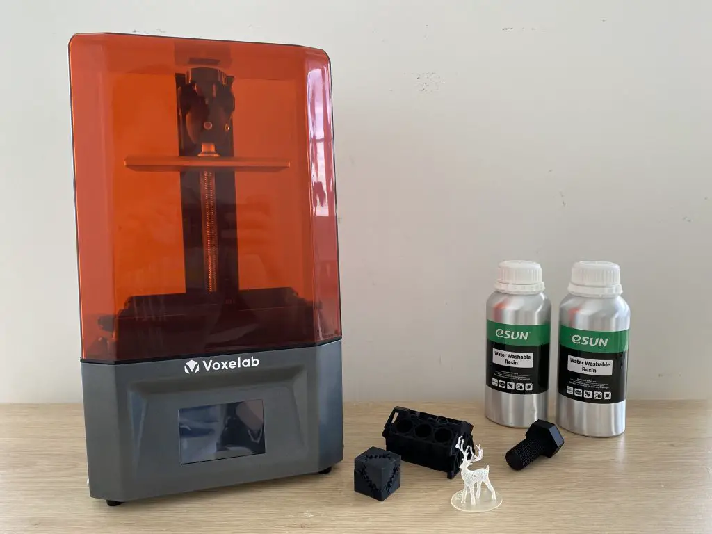
- Creality Ender 3 V2 3D Printer – Buy Here
- TS100 OLED Soldering Iron – Buy Here
- Dremel Versatip Soldering Iron – Buy Here
- Fluke Multimeter – Buy Here
What Hardware Are We Going To Be Replacing?
Let’s start off by taking a look at what hardware we’re going to be replacing within the original weather station.
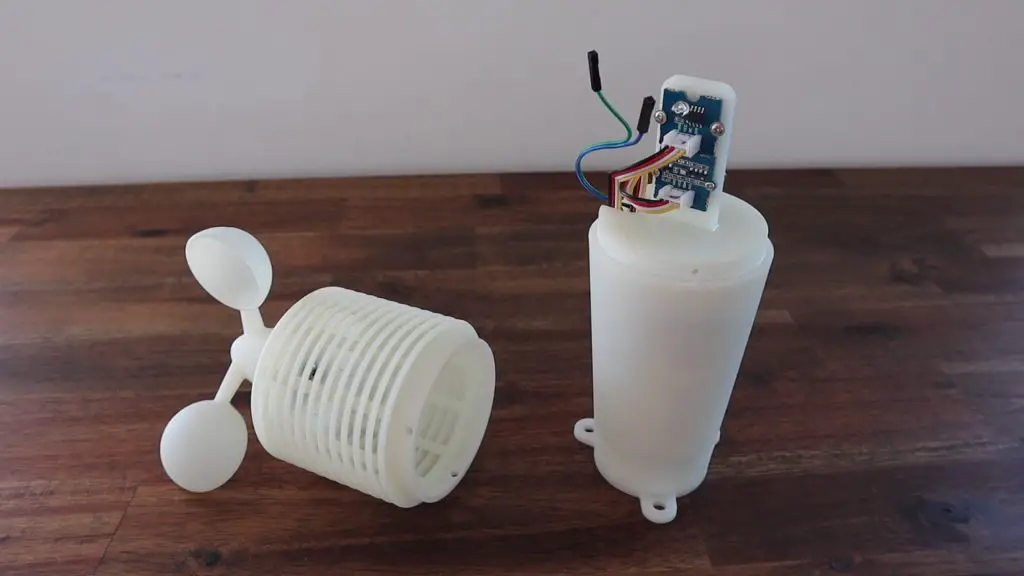
The original build used a DHT11 temperature and humidity sensor. Quite a few people mentioned that this sensor isn’t particularly accurate and is quite slow.
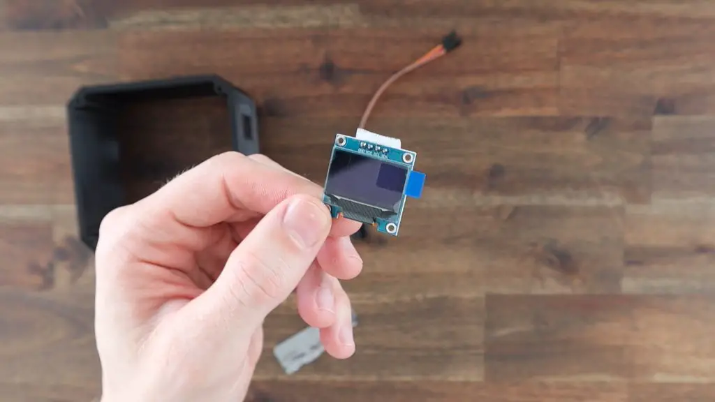
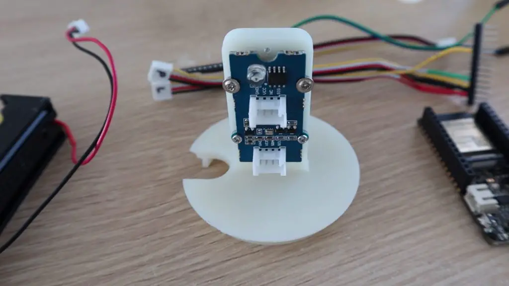
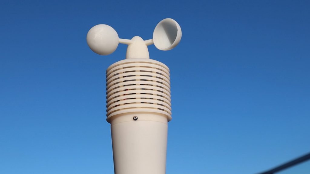
Most suggested replacing it with a BME280 sensor, so that’s what we’re going to do. This sensor measures temperature, humidity and pressure, so I can also remove the separate pressure sensor from my original build. I’ll leave the light sensor at the top in place.
The next change that was suggested was again made by a number of people, and that was to replace the reed switch on the anemometer, or wind speed sensor, with a Hall Effect sensor. The reed switch, being a mechanical device, has a limited number of operating cycles before it wears out. Given that it could be switching up to 150,000 times a day, it probably won’t take too long to wear out either.
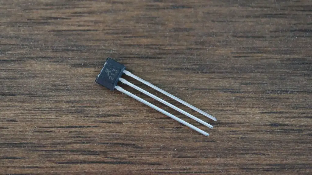
I haven’t used a Hall Effect sensor on a project before, and there are quite a few different options available, so the one I choose was an Allegro A3213. This sensor is polarity independent and has a latched digital output, so it’s quite a good fit as a replacement for a reed switch.
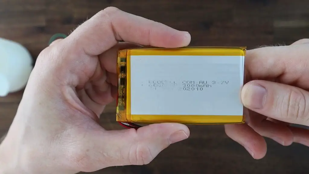
The final hardware change that I’m going to make is to replace the original 1850 lithium-ion cell with a higher capacity 3000mAh lithium polymer cell. This cell will give the station about 30-50% more energy storage capacity, so it’ll be able to run longer between charges. It also has built-in overcharge and over-discharge protection.
While we’re on the topic of powering the weather station, I’m going to be adding a solar panel and solar power management board nearby to re-charge the battery. This isn’t a modification to the actual weather station as such but is another useful addition.
Replacing The Weather Station’s Sensors & Battery
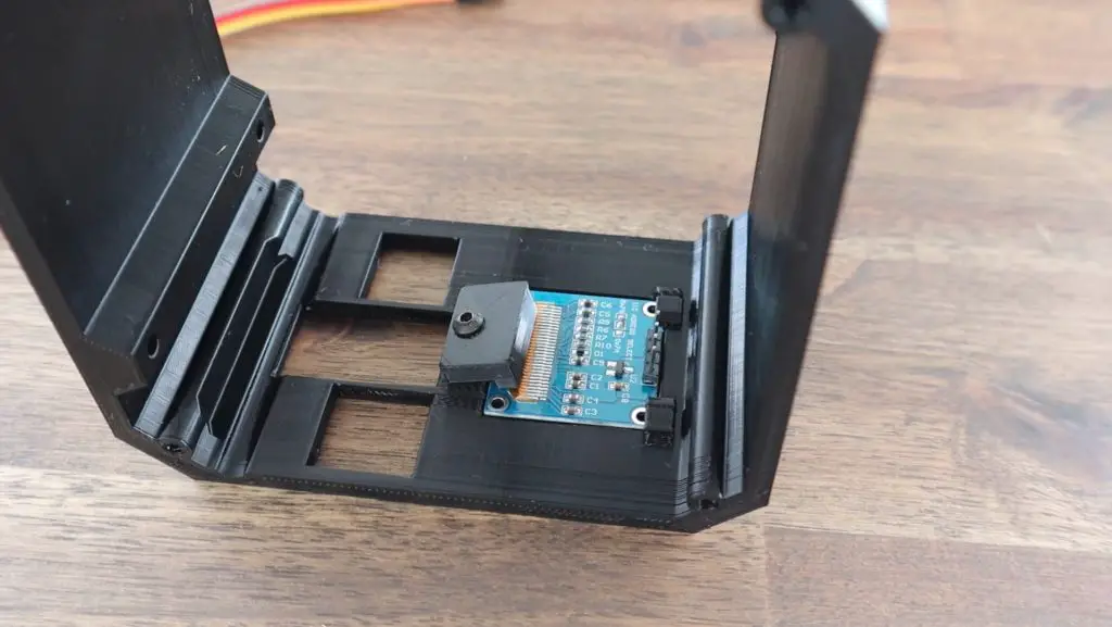
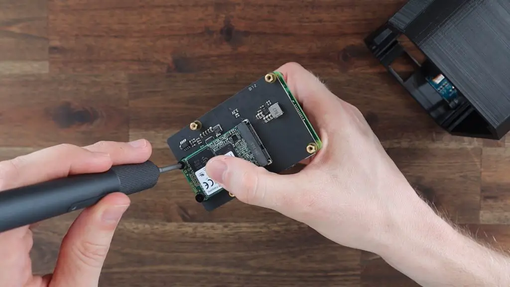
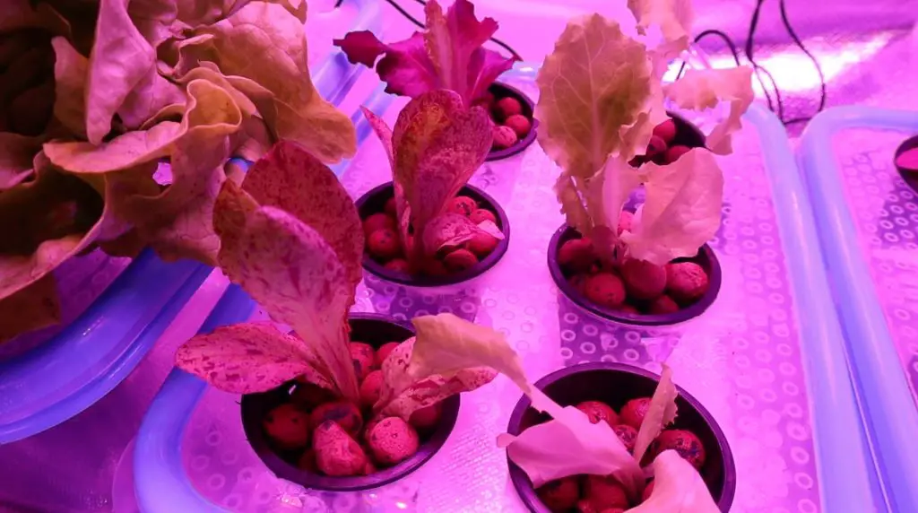
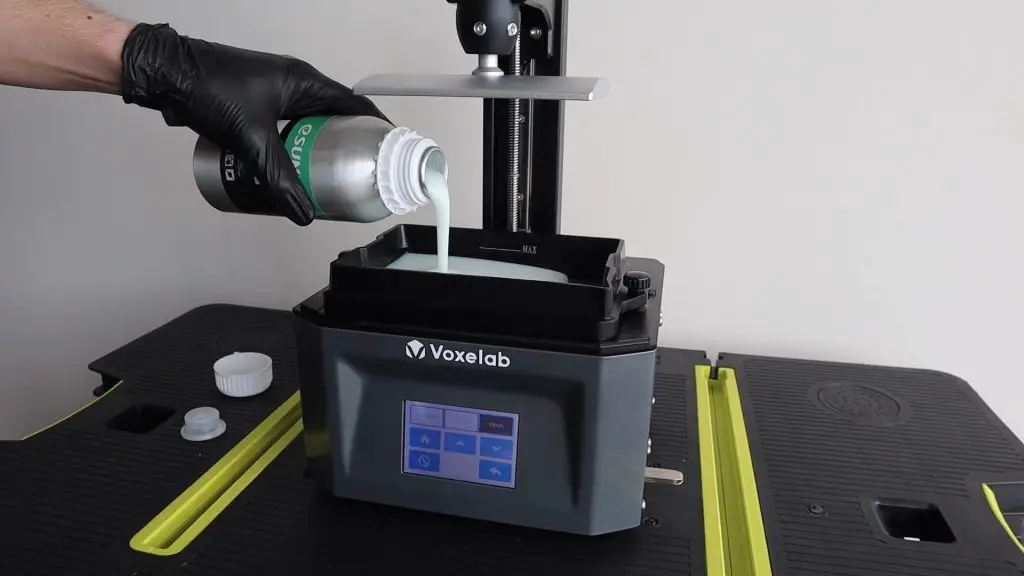
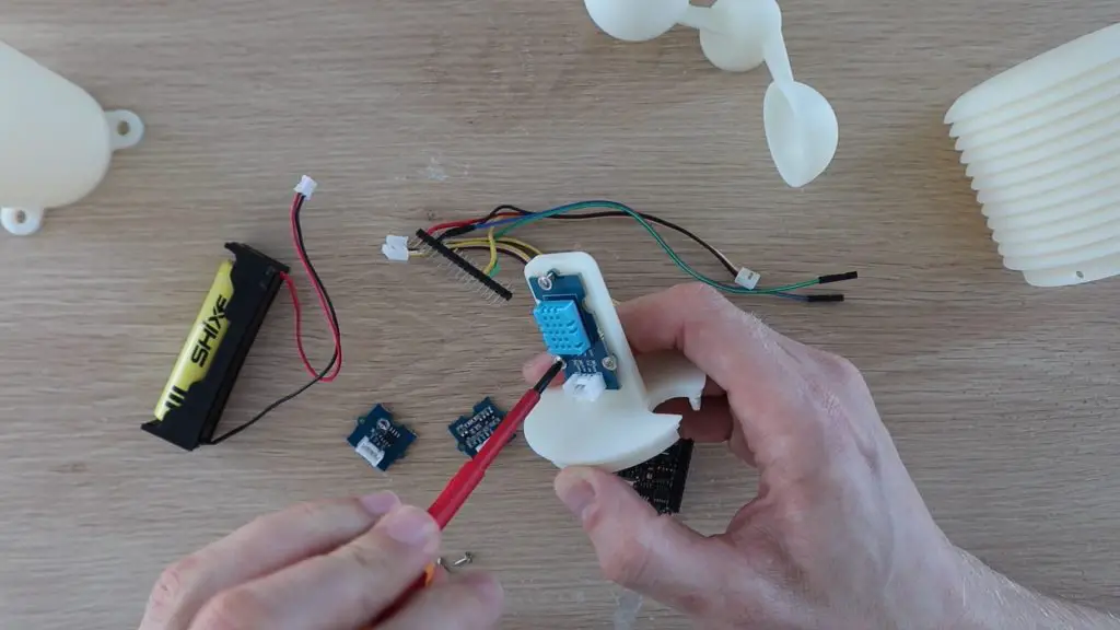
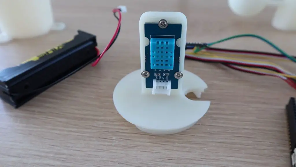
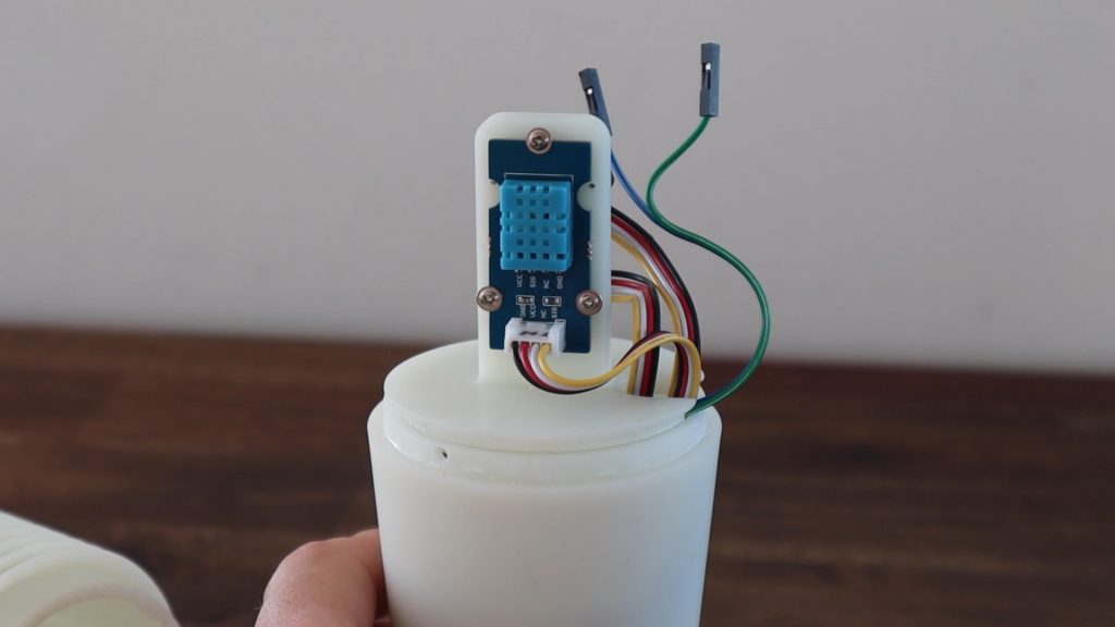
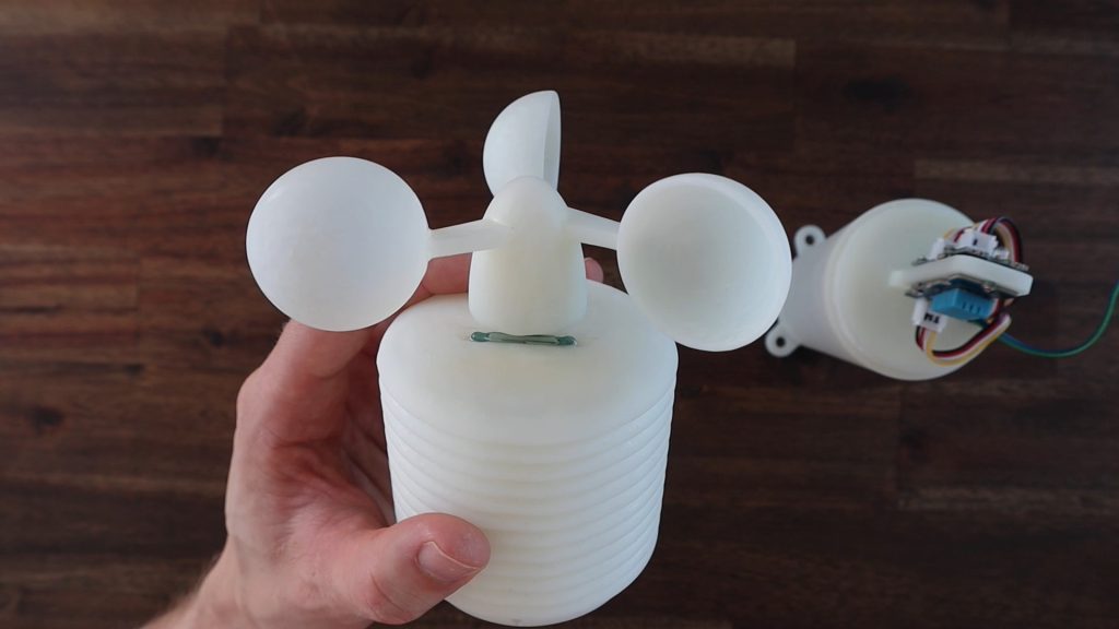
I’m going to install the BME280 module with the sensor facing towards the stand. This allows me to re-use the original sensor’s mounting holes and I won’t have to modify the sensor pints. This also shields it from any direct sunlight that manages to get into the housing and gives it a bit more protection from moisture. The sensor is still spaced slightly away from the stand, so there aren’t any pockets of air trapped around it.
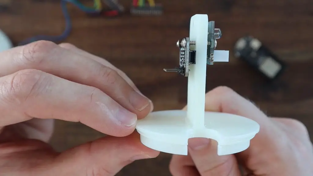
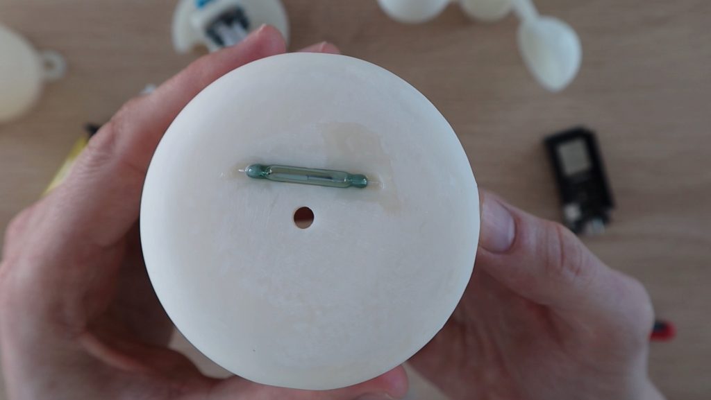
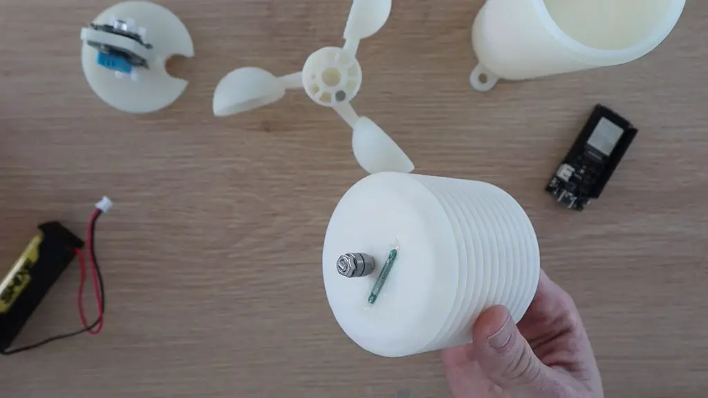
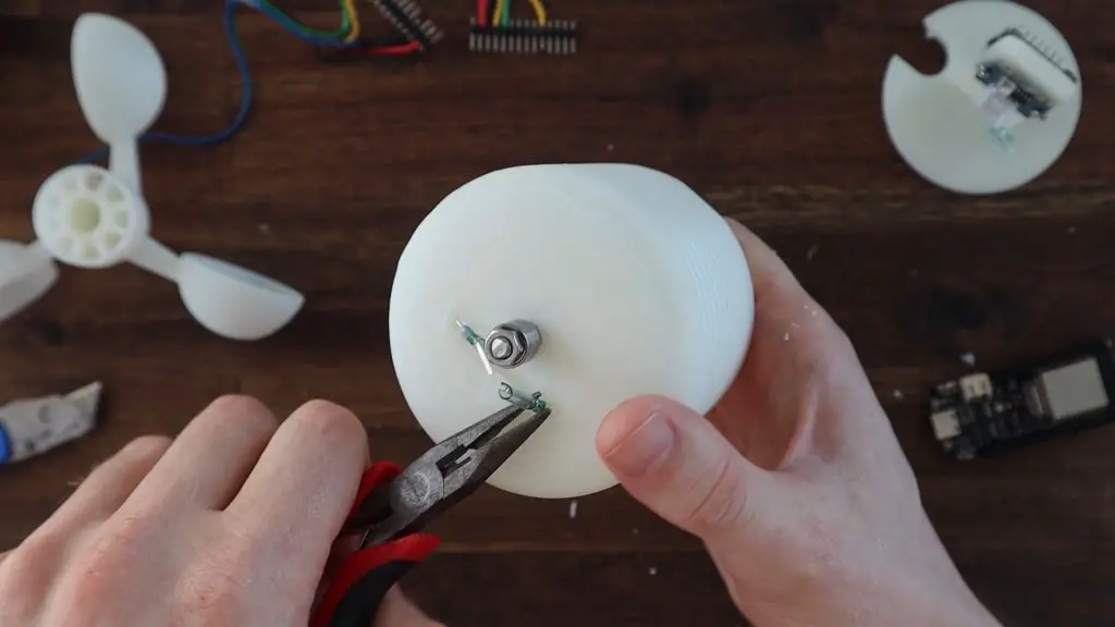
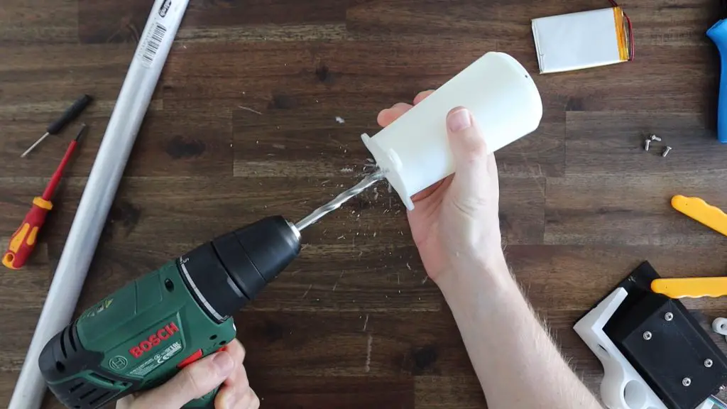
Replacing the reed switch with the Hall Effect sensor is a bit more involved. I have to first remove the reed switch, which I moulded in place with resin because I didn’t intend to ever remove it. I also didn’t want to have to print a whole new housing just for the new sensor.
After a couple of failed attempts, a drill eventually worked to crack the switch’s glass tube and I could then pull out all of the pieces. I also cracked the top of the housing in the process, but fortunately, resin prints repair quite well with additional resin, so that’ll be an easy fix.
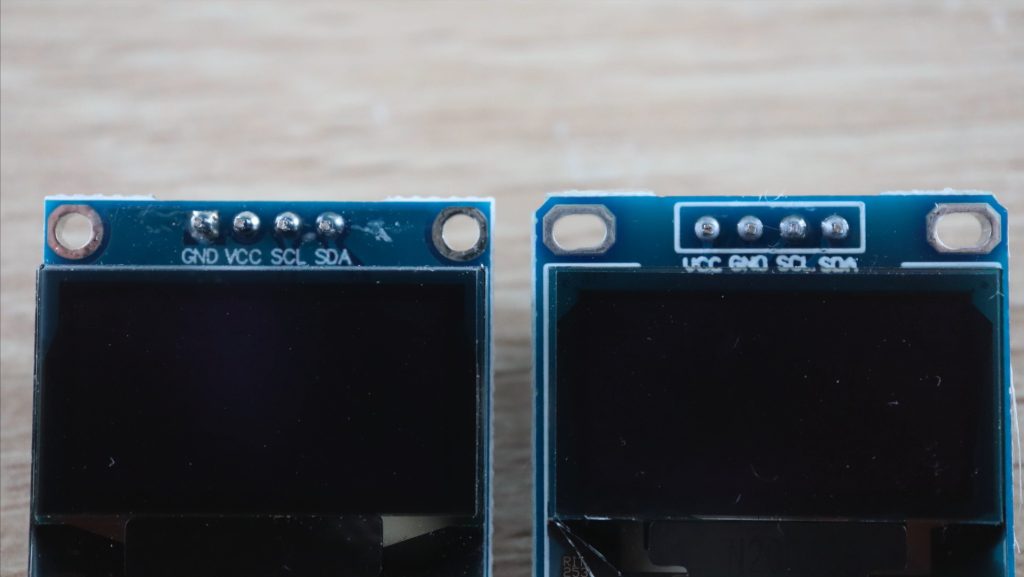
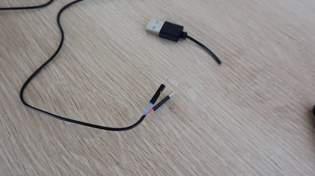
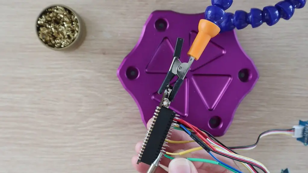
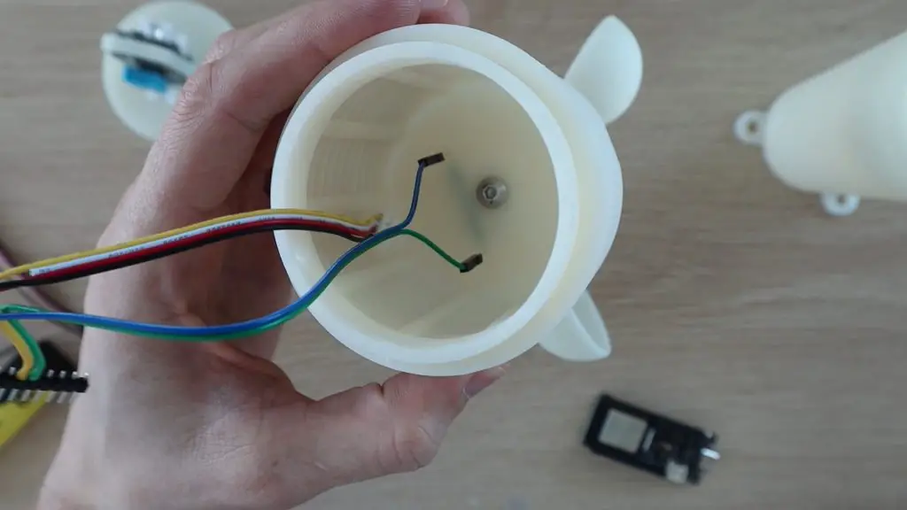
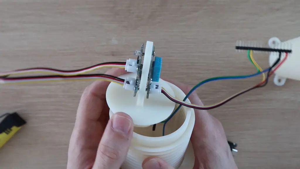
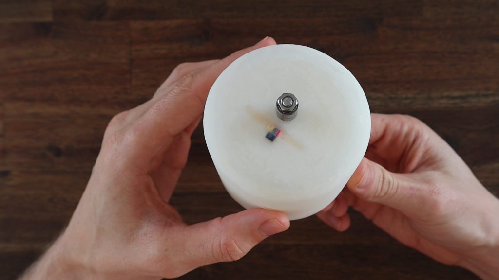
I soldered some wiring to the sensor before installing it in the housing so that I can again pour some resin around it to hold it in place and seal off the top of the sensor housing. It’s important to make a note of the wire colours connected to each leg of the sensor as you’ll need this when connecting them to your Firebeetle board.
I bent the legs of the Hall Effect sensor at 90 degrees about 3mm from the sensor so that they could be directed through the hole in the housing and the face of the sensor would then be facing towards the bottom of the anemometer.
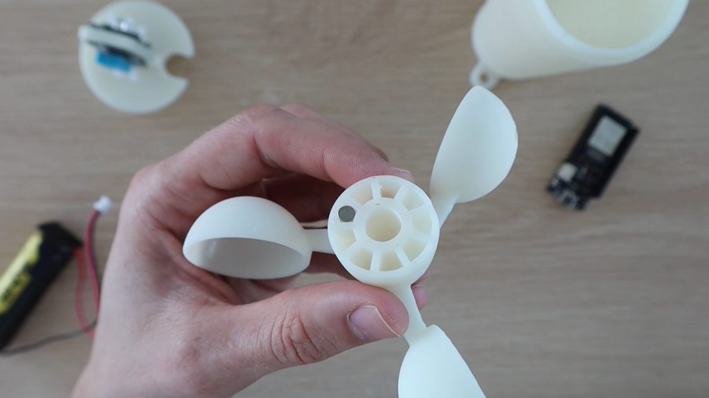
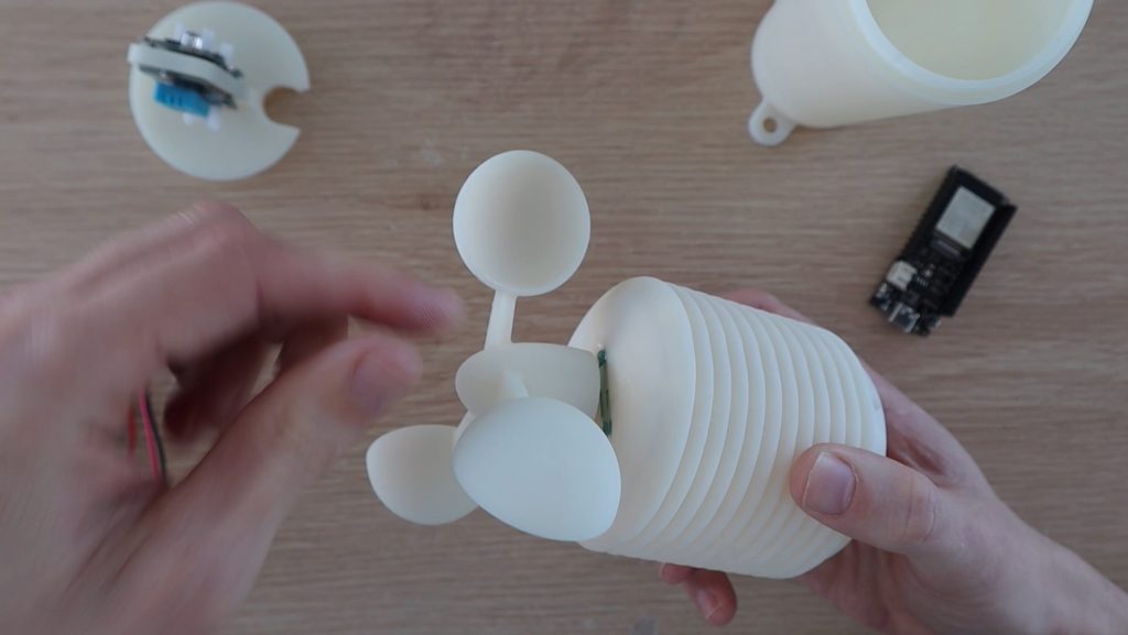
I shouldn’t need to do anything with the magnets in the anemometer, if they worked for the reed switch then they should easily work with the Hall Effect sensor as well, as they’re typically a bit more sensitive.
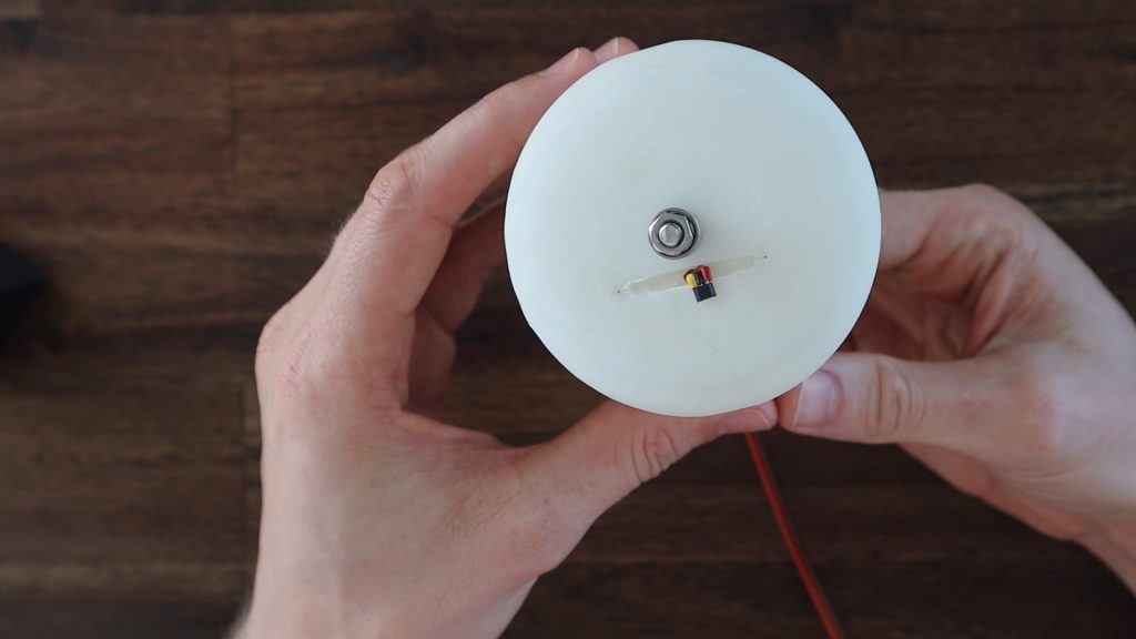
I then filled the void and area around the sensor with some resin to hold it in place. I then left this outside in the sun for a few hours to cure before lighting sanding it with my Dremel for an even finish.
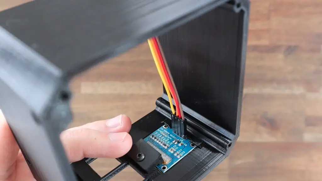
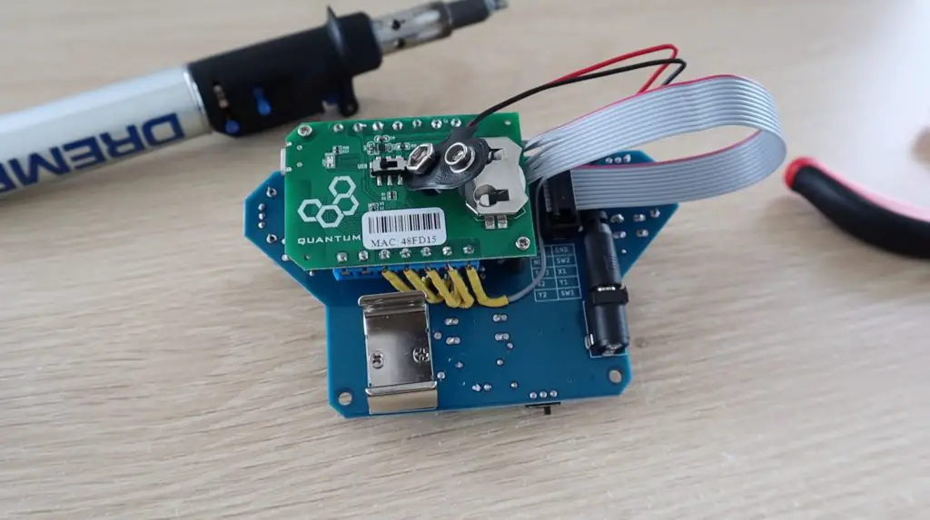
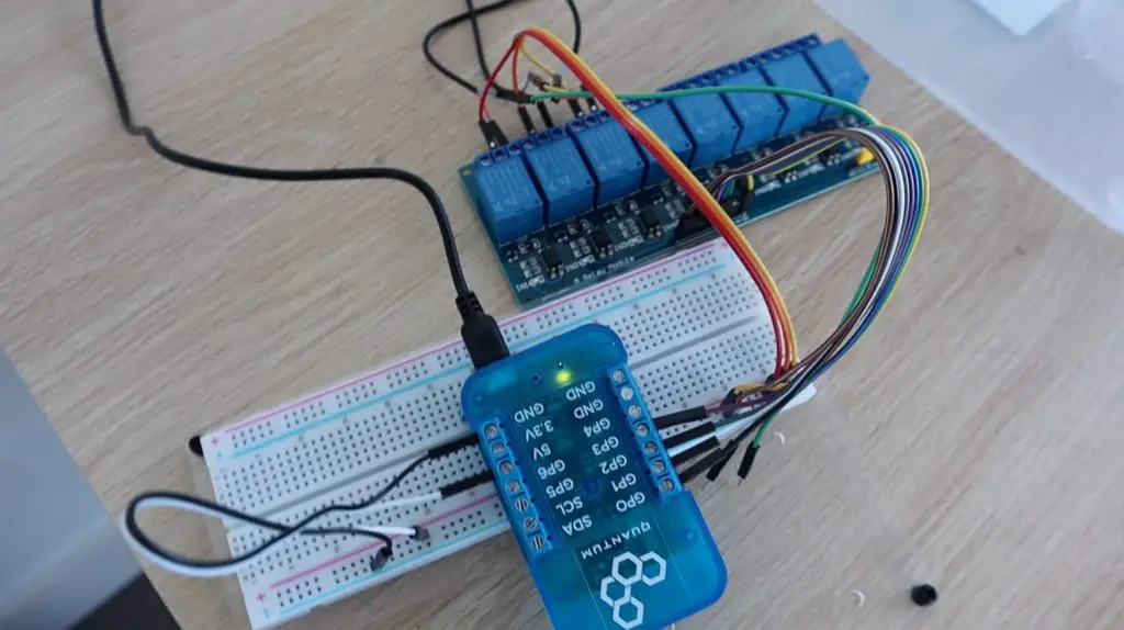
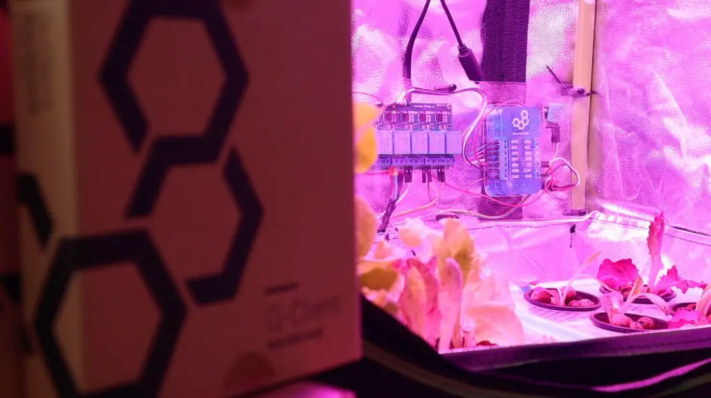
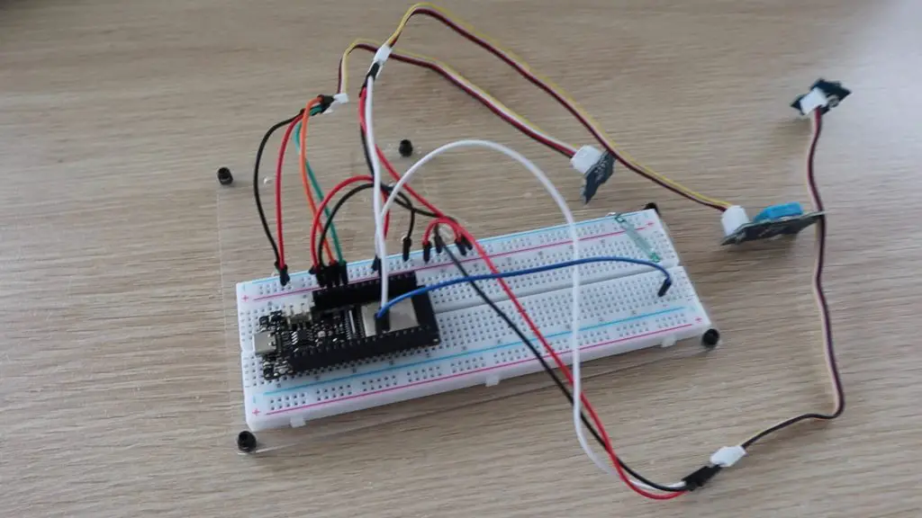
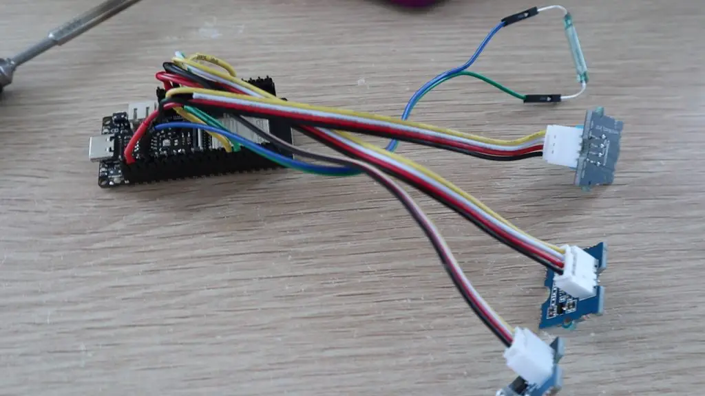
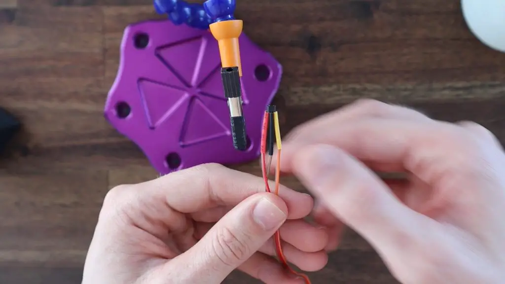
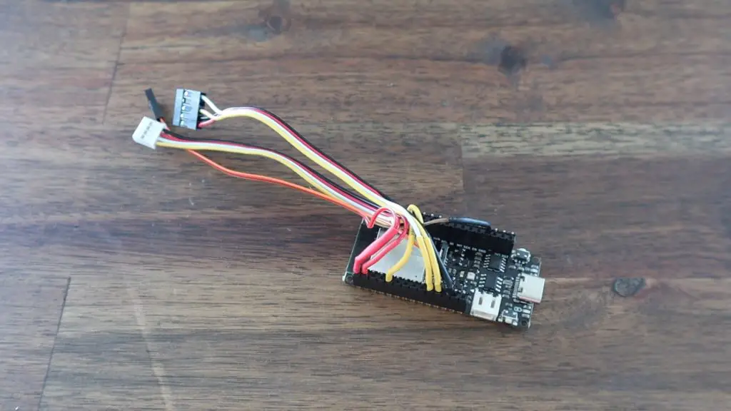
Now that the sensors are in place, we can make up a new wiring harness to connect them to the Firebeetle board. I also made some changes to the wiring to power the sensors. Rather than connect them directly to power and have the sensors stay on the whole time, a suggestion was made to turn the sensors on and off using the IO pins, as they don’t draw much current.
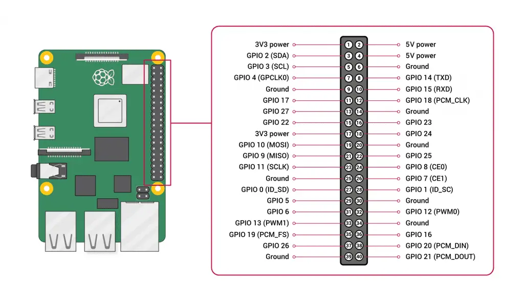
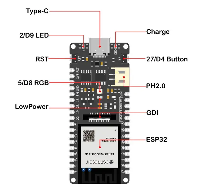
So I’ve got the BME280 sensor’s power pin (VIN) connected to digital pin 16 and the light and Hall Effect sensor’s power pins connected to digital pin 17. This means I can now turn the sensors on only when measurements are taken, so this should further extend the battery life.
The other connections remain as per the original design. The BME280 sensor is connected to the I2C pins, the light sensor to pin 36 and the Hall Effect sensor to pin 0 on the Firebeetle board.
Improvements Made To The Code
Now that we’ve got the sensors connected up to the board, we obviously need to make some changes to the code so that they can be used.
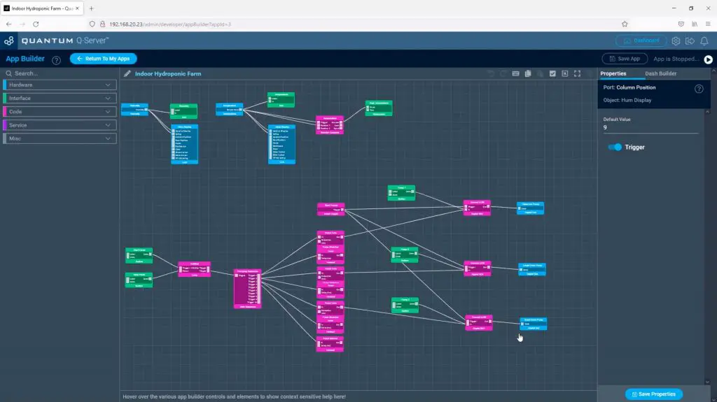
Here is my revised version of the code:
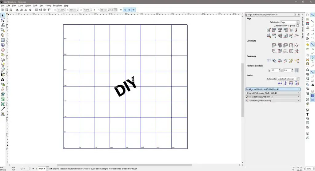
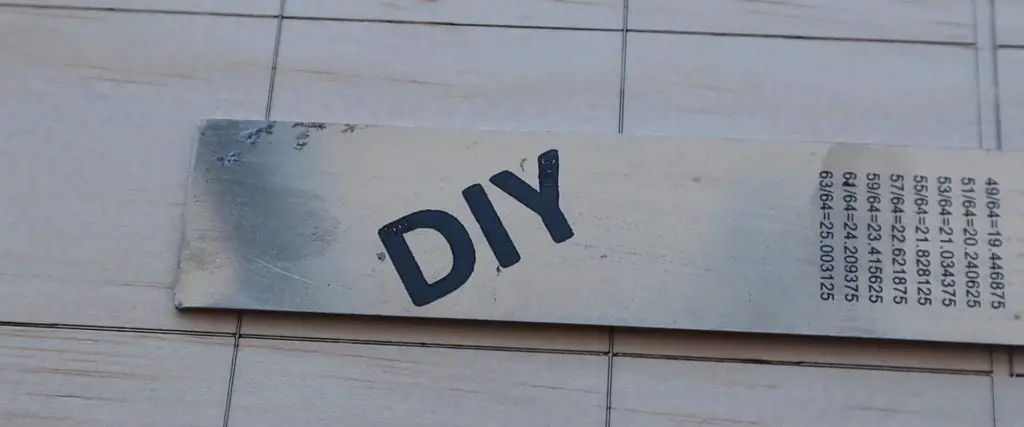
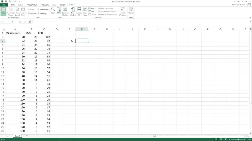
The first and probably most significant is a look-up table for the wind speed. Ian Finnimore had a number of ideas to improve this part of the code, pointing out that the relationship between the wind speed and the rotation time is not linear. He also included a formula to use as a starting point. I used this along with some measured data to eventually calibrate the sensor, and the code now uses this lookup table to find the actual wind speed based on the rotation time. This also allows calibration adjustments to be made to select individual speeds or the complete range.
I also reduced the cycle time to about 8 seconds, as this is all that is needed by the wind speed sensors. Even at the lowest measurable wind speed, the anemometer would rotate at least three times during this period, which is enough for the calculation.
Next I made the changes to the digital pins to turn the sensor on and off as they’re needed, rather than staying on all of the time. This just involved setting each sensor’s digital pin high a little before taking the reading from them and then turning them off again.
Lastly, I moved the WiFi connection right to the end of the cycle so that the WiFi connection isn’t active for the full cycle time, which saves power. I also added a timeout to the WiFi connection attempt routine. In my previous code, the board would stay on and keep attempting to connect to the WiFi network even if it was temporarily unavailable or there was an error. Getting stuck in this loop obviously dramatically drained the battery and resulted in the station dying in a day or two if it occurred. It’ll now try for only 10 seconds and if there is no connection available it’ll timeout and go to sleep anyway.
Testing The Weather Station’s New Power Consumption
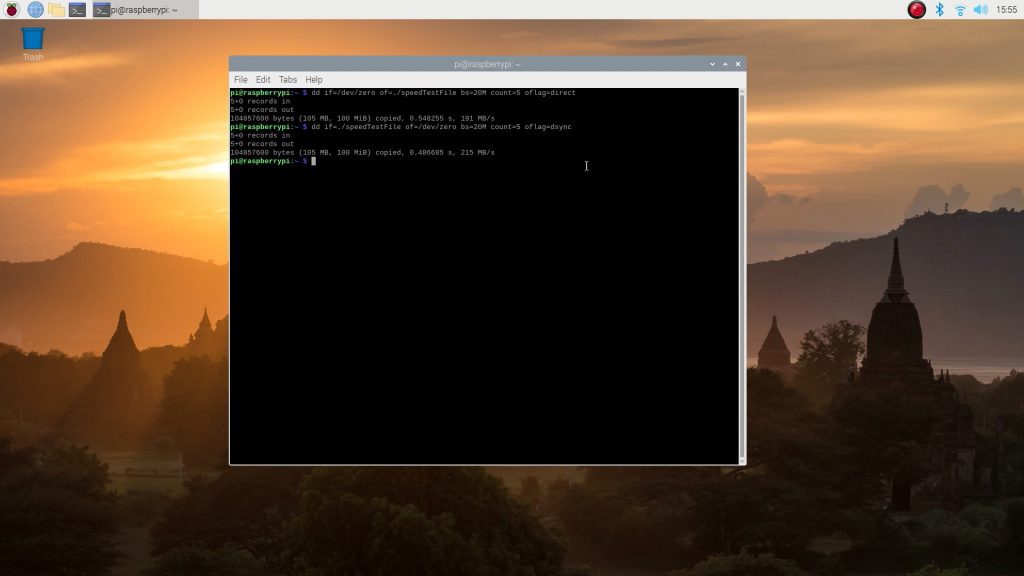
We’ve made a few improvements to the hardware and software, which should result in lower power consumption, especially during the sleep period, so let’s test it.
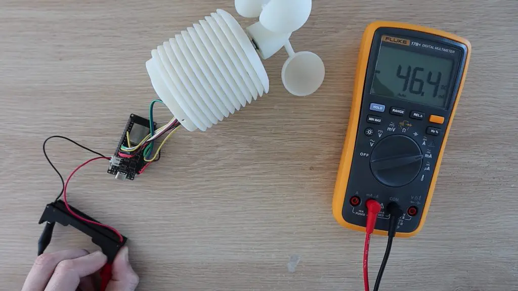
I connected my multimeter to the supply and turned the board on.
The current draw spikes to a little over 100mA when starting up and then quickly settles around 45-55mA while it is taking readings, which is for the majority of the “on” period.
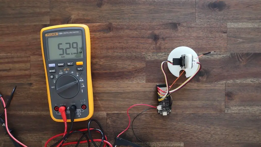
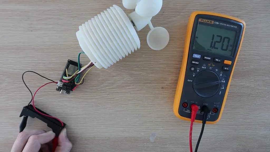
The most significant improvement was during the sleep period. It now goes down to just 0.01mA or 11µA, which is a large improvement over the last version. This is using almost 100 times less power during sleep mode than the previous version.
Note that the multimeter below is now in µA rather than mA shown above. So this is 11.3 thousandths of a mA.

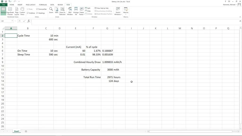
So if we calculate the expected battery life using a 10 minutes cycle time, with 10 seconds of “on” time and 590 seconds of “sleep” time in each cycle, and an average draw of 60mA while on, with the new battery we should get a little under 3000 hours or 124 days of run time. So that’s around four months off a single charge, which is also a great improvement.
Mounting And Adding Solar Power
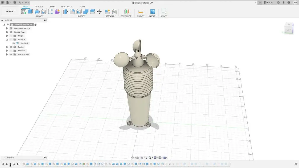
I previously mounted the weather station directly onto a flat surface using the three feet on the base. This time, I want to rather mount it onto a pole so that there are no flat surfaces around it to affect the wind speed and I want to add a solar panel mount onto the same pole.
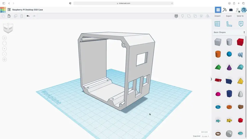
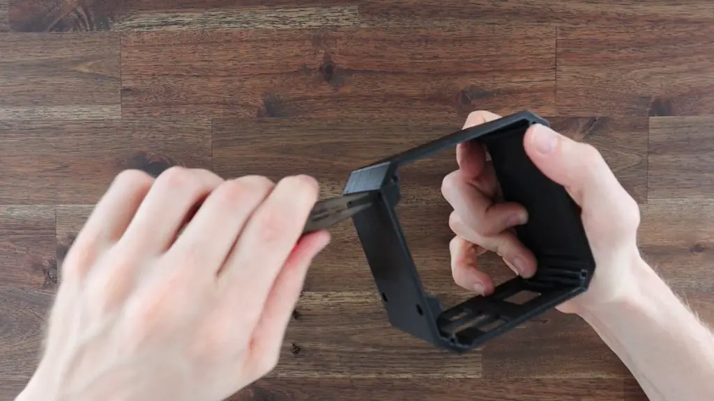
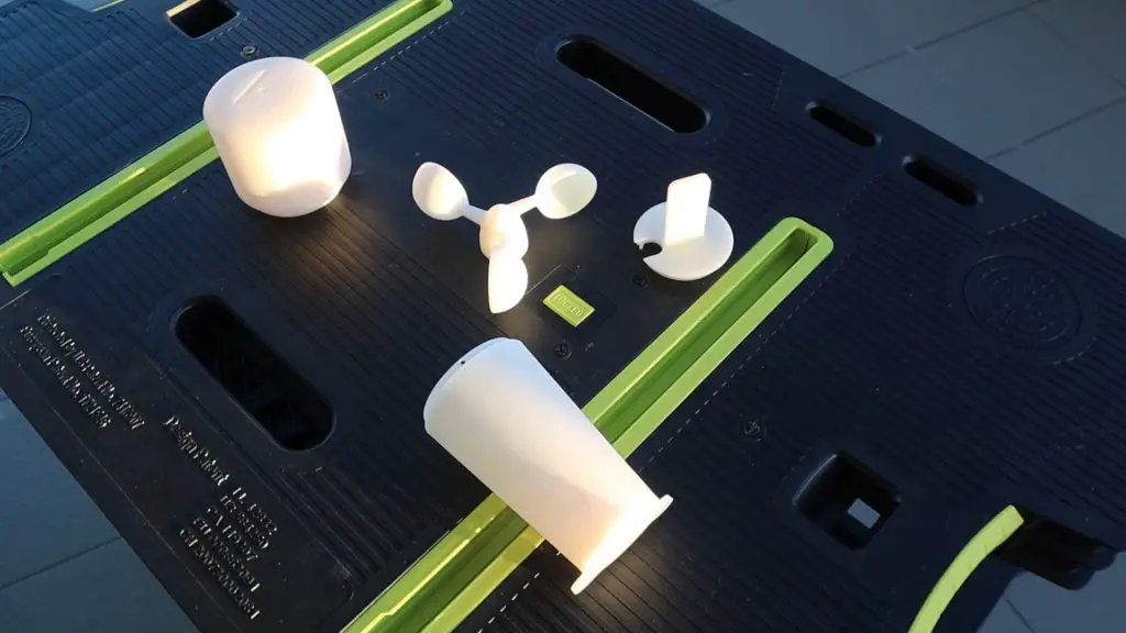
So I designed and 3D printed a bracket to mount the weather station onto a 25mm pole, which is easy to then mount onto a railing or fence post.
Now I know that improving the battery life means that it hardly ever needs to be charged, but to make it a truly plug-in and forget weather station, I wanted to add a solar panel so that the battery is kept charged without me having to remember to charge it.
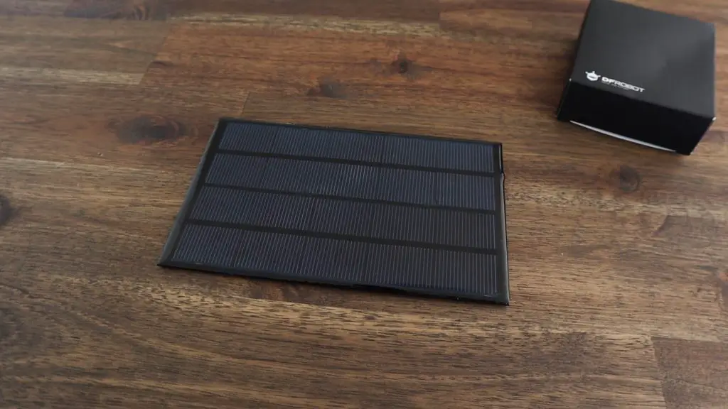
I’m using this 5V panel which I have from a previous project. It claims to be a 1A panel, but that seems a bit optimistic for its size. In any case, it’s way more than what we need to replace the 25 or so milliamp hours used each day. It’ll work well to provide some additional capacity for longer periods of overcast days and allow for a drop in efficiency over time.
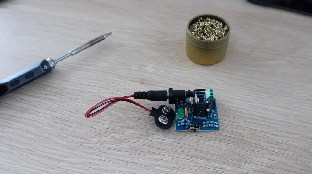
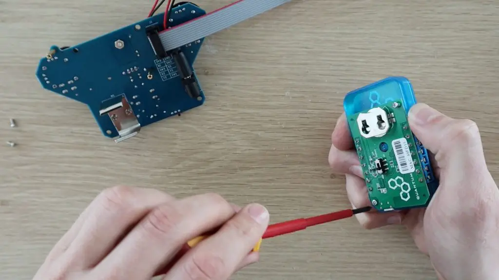
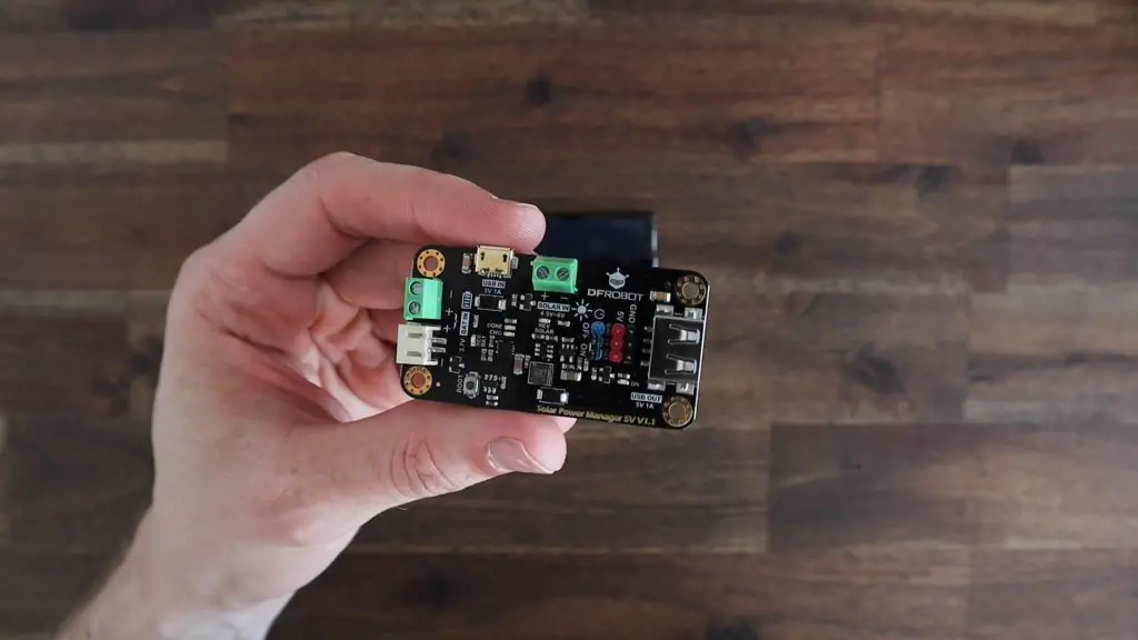
I’m going to use a DF Robot solar power management board to control the charging of the battery. This board basically takes the power provided by the solar panel and uses it to charge the battery and provide a regulated supply to the Firebeetle board.
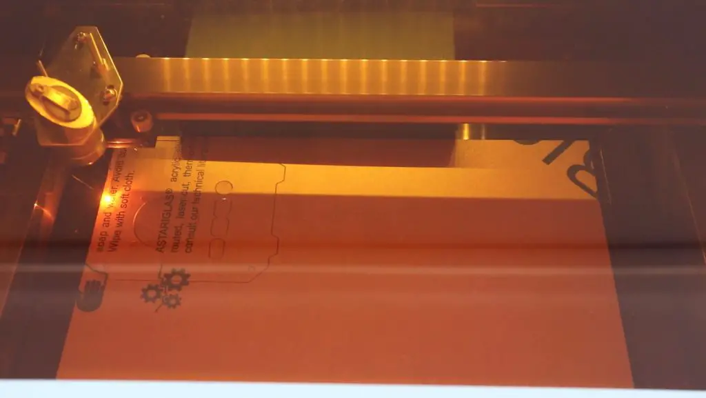
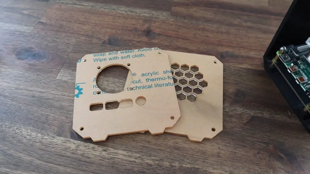
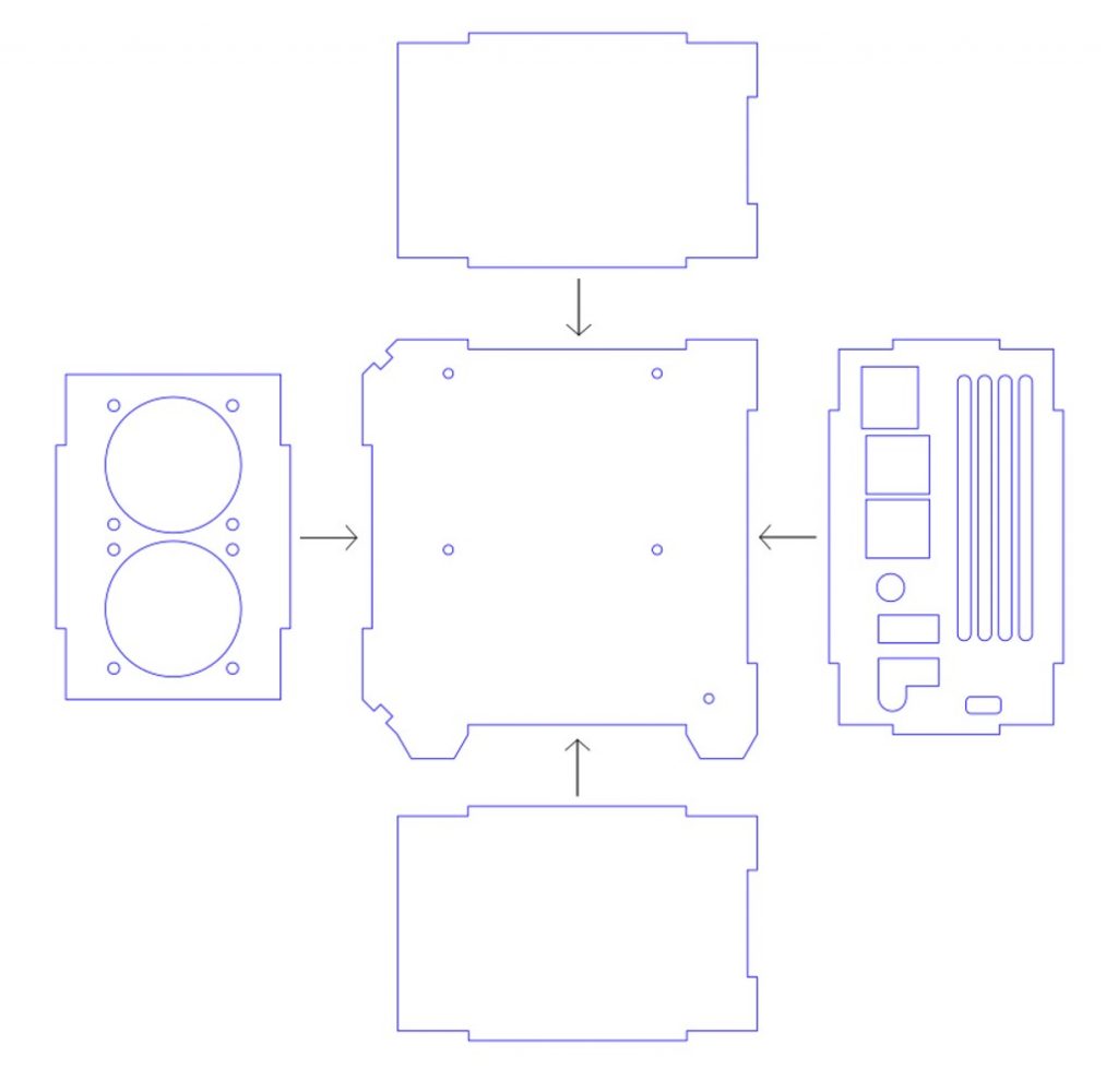
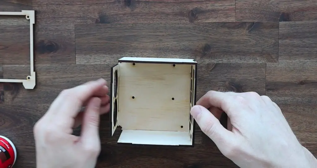
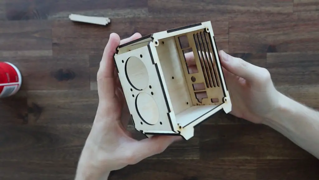
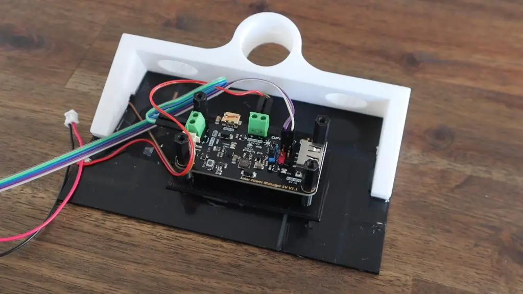
I’ve also made a 3D printed bracket and housing to hold the panel and the solar power management board and these will be installed on the same pole underneath the weather station.
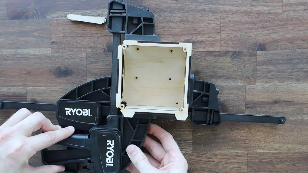
The bracket for the solar panel and the holder for the solar power management board are glued onto the solar panel using some epoxy. I used four nylon standoffs to hold the board in place and provide supports for the cover.
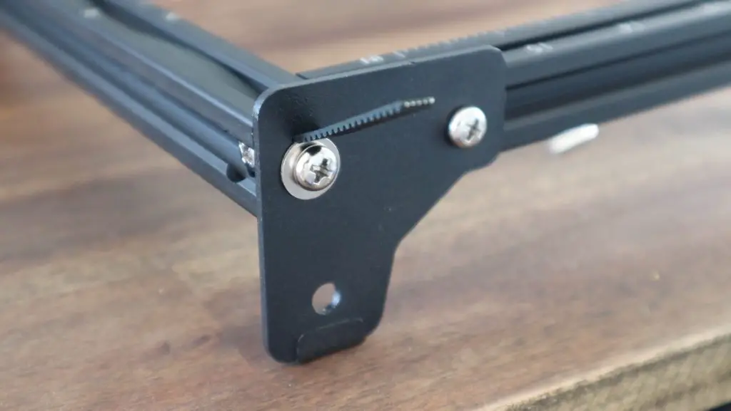
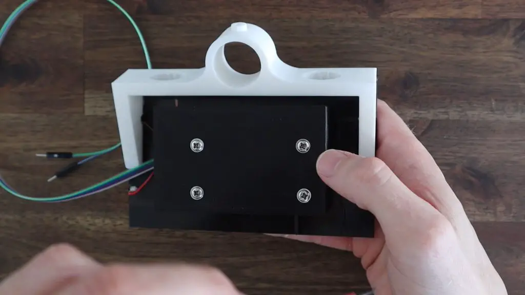
The cover can then be held in place using four screws that came with the solar power management board.
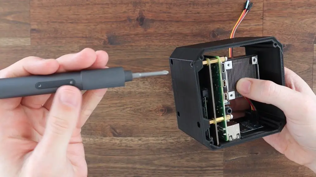
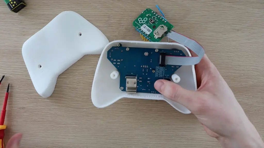
I drilled an 8mm hole in the bottom of the weather station base to run the wiring to the battery and to the Firebeetle board. Be careful drilling through resin prints as they’re quite brittle. It doesn’t take much force to crack them entirely (like I did with the sensor housing).
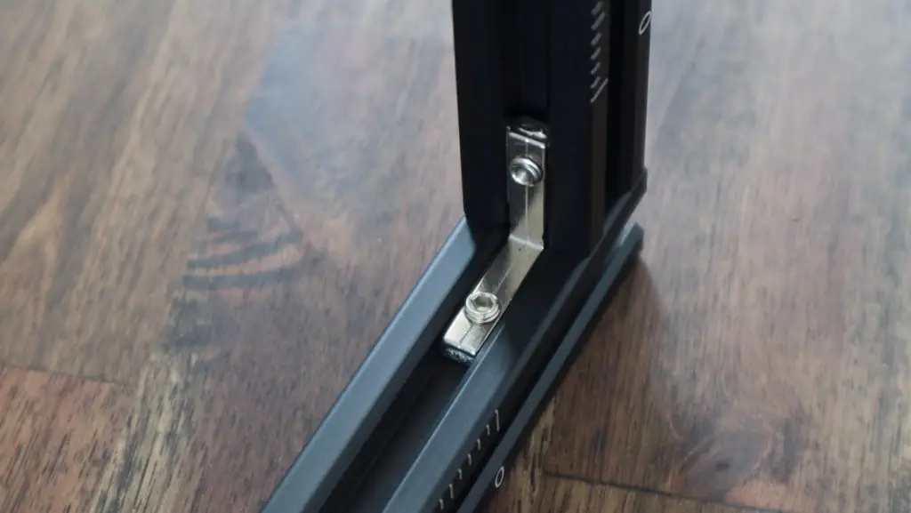
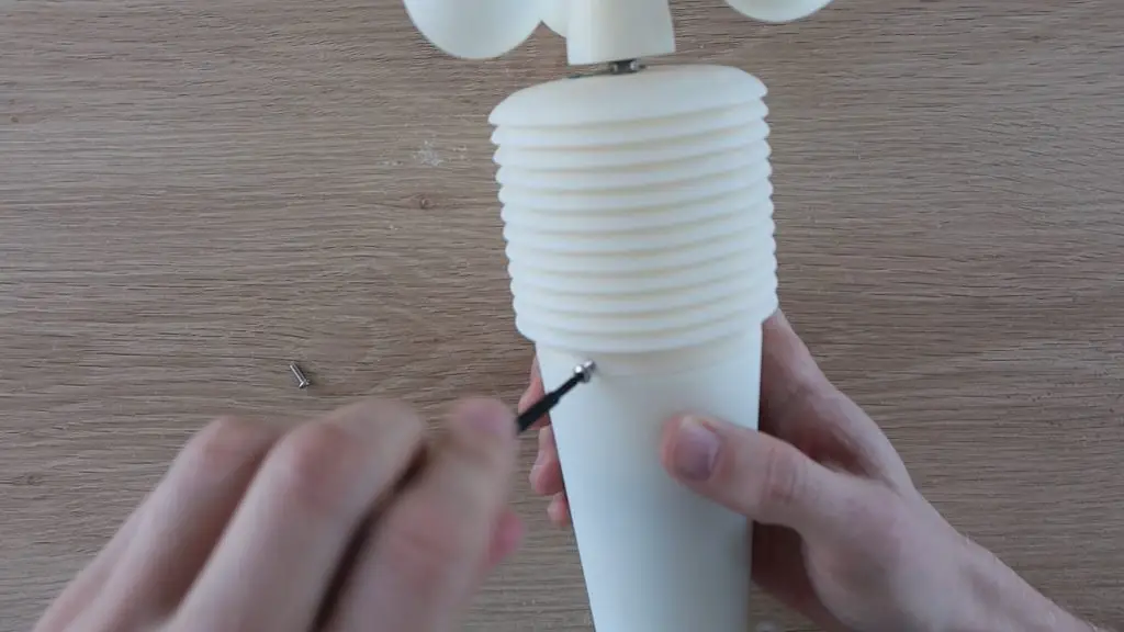
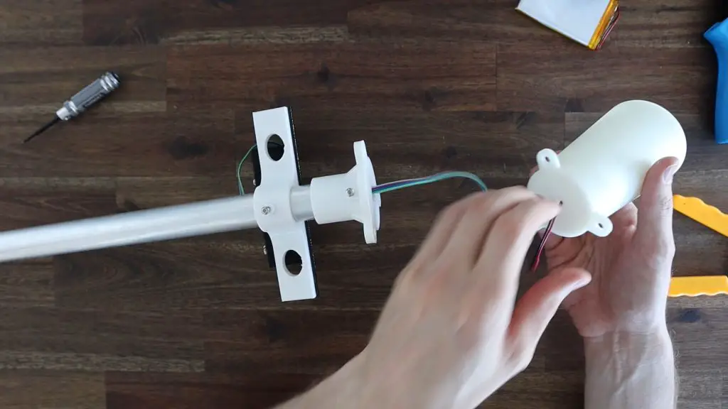
The solar panel bracket is then mounted onto the pole and the weather station is mounted onto the 3D printed bracket on the end of the pole. An M3 screw and nut are used to hold each in place, the nut sits on the inside of each bracket and helps press the screw against the pole to secure them. The wiring is fed through the base and then plugged into the battery and the Firebeetle board.
Using The Modified Weather Station
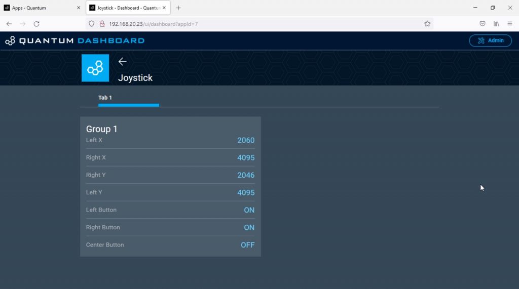
I mounted the weather station’s pole outside and it has been running for about three weeks at the time of writing this post.
This is a sample of the temperature graph, you can view my full weather station dashboard here, or visit my public Thingspeak channel.
Since the weather station’s power consumption has gone down quite substantially, I’ve been thinking of trying to power it using some sort of supercapacitor arrangement rather than a battery.
Let me know if you’ve done this or if you’ve got any suggestions for this in the comments section.