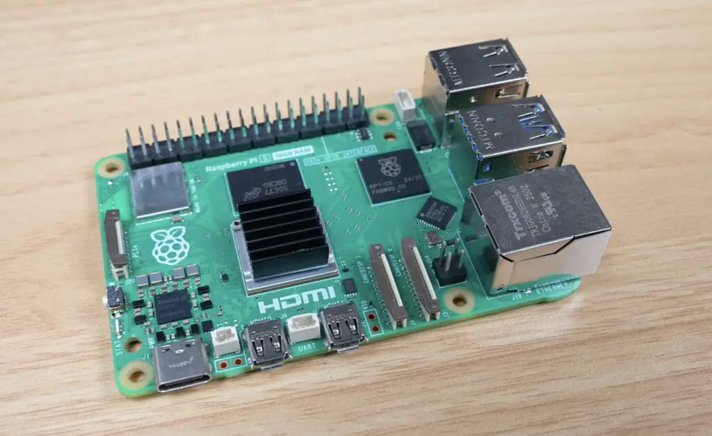
The Pi 5 is the most powerful Raspberry Pi that is currently on the market, and with the increase in power comes an increase in heat. While there are already quite a few cooling solutions available, I wanted to tackle this project on my own and design a Pi 5 Peltier cooling system that can modularly be scaled up to ridiculous proportions.
I’ve always wanted to try cool a Pi with a Peltier cooler or TEC. So today we’re going to try and push Pi cooling further than I’ve ever done before, hopefully getting the Pi’s CPU down to below 10 degrees.
Here’s my video of the project. Read on for the write-up;
Where To Buy The Cooling Components
Since this project is largely a custom build, you won’t be able to replicate it without making up some of the components yourself, but these are all of the bought-out components that I used for my Pi 5 Peltier Cooling build:
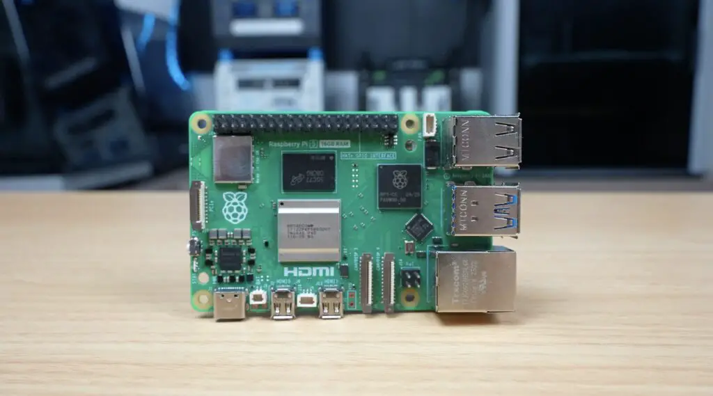
- Raspberry Pi 5 – Buy Here
- Pi 5 Official Power Supply – Buy Here
- Pimoroni NVMe Base – Buy Here
- Lexar NM620 NVMe SSD – Buy Here
- Passive Aluminium Heatsink – Buy Here
- 40mm 5V Fan – Buy Here
- 120mm CPU Tower Cooler – Buy Here
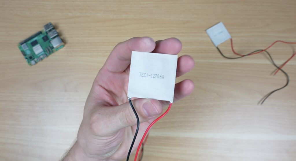
- 40mm 30W Peltier Module / TEC 12706 – Buy Here
Tools & Equipment Used:
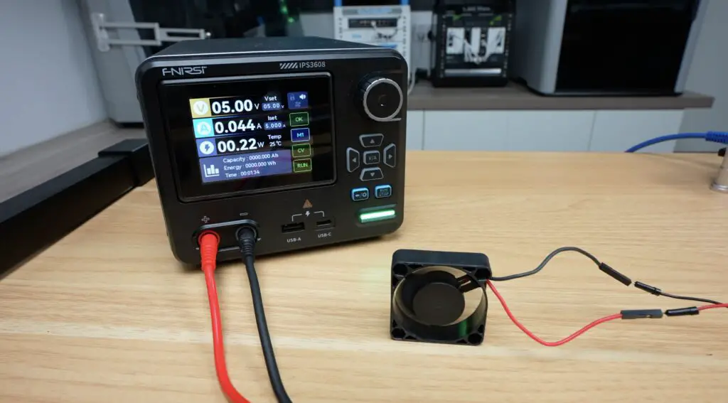
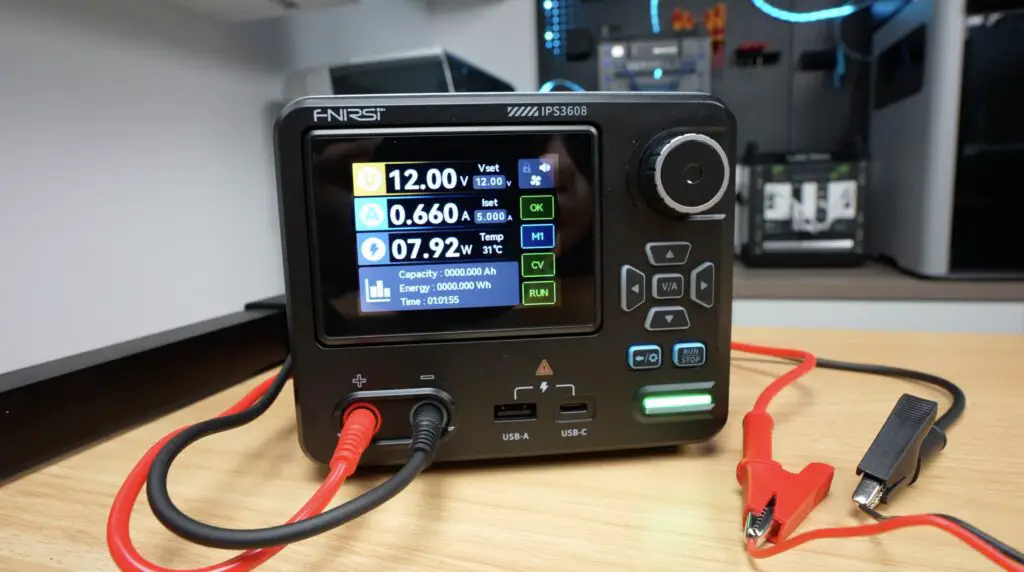
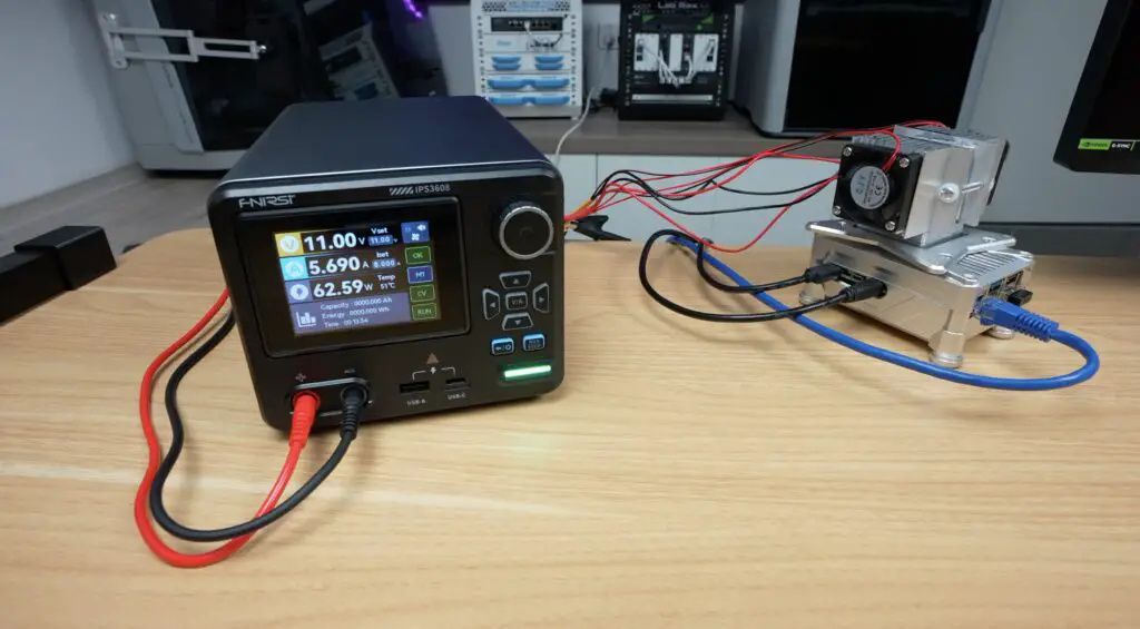
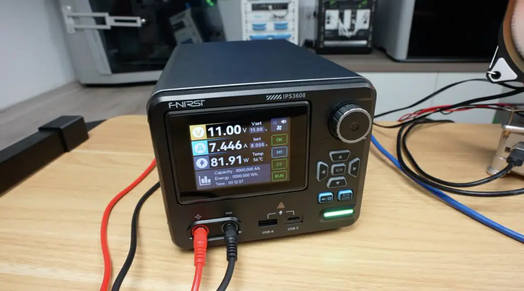
- FNIRSI IPS3608 Power Supply – Buy Here
- USB C Pencil Screwdriver – Buy Here
- Infiray P2 Pro Thermal Camera – Buy Here
- Sound Level Meter – Buy Here
Some of the above parts are affiliate links. By purchasing products through the above links, you’ll be supporting my projects, at no additional cost to you.
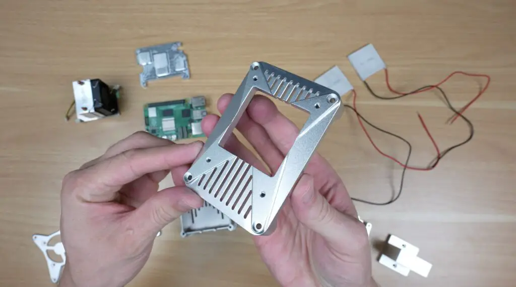
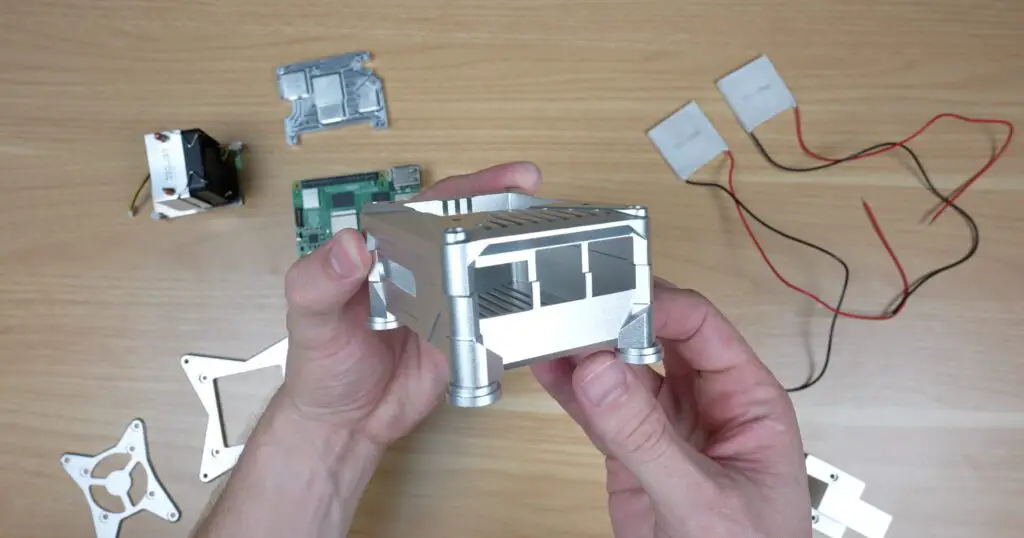
Designing The Enclosure and Modular Cooling Components
Ice tower style coolers like this have been around since the Pi 4 and are generally already considered to be overkill, even for a Pi 5. The problem that I’ve got is that there’s no easy way to attach a TEC to one, or to any other standard Pi heatsink for that matter. So I started out by designing a new enclosure in Fusion360.
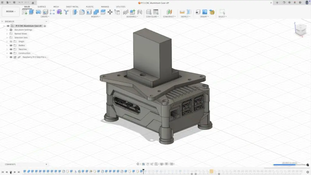
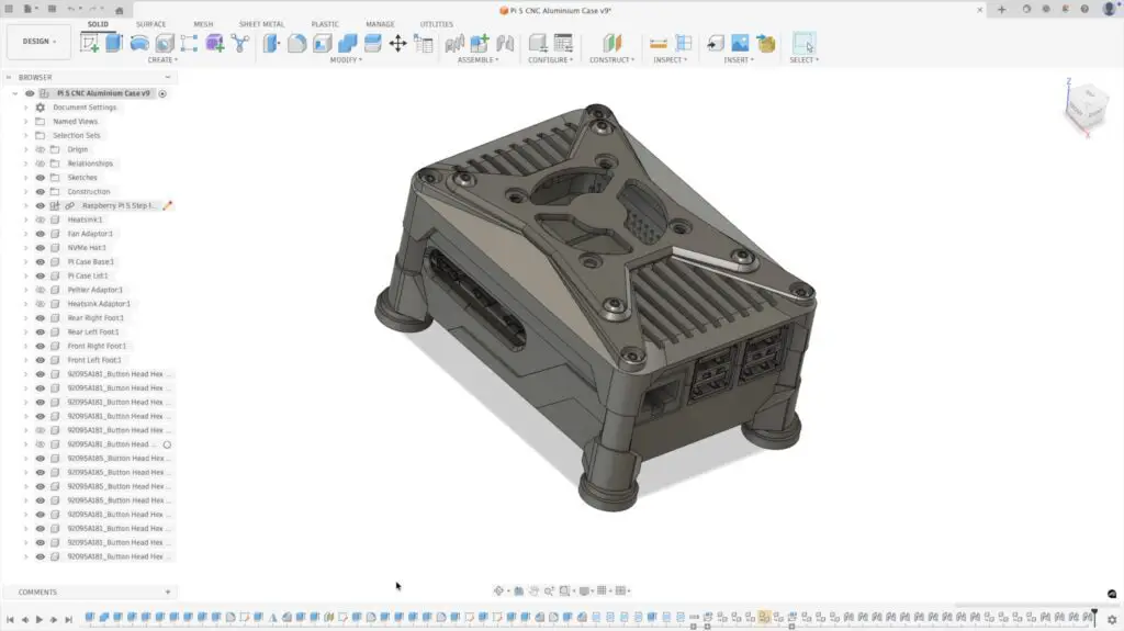
Unlike my other enclosures, which are designed to be 3D printed, this one is designed to be CNC machined from aluminium. Best of all, it is designed with a couple of modular brackets and blocks which allow me to step cooling up from a simple passive heatsink, moving through adding fans, to a full-size CPU cooler and finally to two TEC configurations where things get a bit ridiculous.
There is also a very real chance of condensation on and around the heatsink, which should make testing interesting.
First and foremost, I want to see how close I can get the CPU temperature to zero, but I’d also like to run a Geekbench 6 benchmark at the two extremes to see if there is any difference in performance. After all, if there’s no performance benefit, then it’s not really worth doing.
Next, I needed to get the enclosure components made up.
Now I could have done what I’ve done previously and made them up on my Carvera Air, but milling this amount of aluminium would have taken a long time. So I got PCBWay to assist with making up the parts. I’ve previously used them to make up circuit boards for my electronics projects, so when they reached out asking if I’d like to try their 3D printing or CNC services out, I thought why not?
They make it really easy through an online order form where you upload your files and then select a couple of options for tolerances and finishes. I went for anodising afterwards, which was their recommendation, and I’m really glad that I did.
Two weeks later, the parts turned up, and man, do they look better than I was expecting. It’s really cool to see your 3D CAD model turned into something that looks and feels like a premium product.
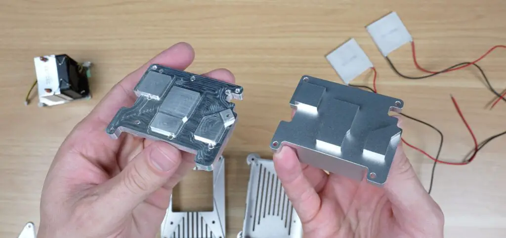
The anodising really makes the components look so much better than I’m able to produce.
I was then quickly sobered by the thought that these components look amazing, but being a first run, I’ve never actually tried assembling them. If you’ve tried designing your own 3D printable parts, then you’ve probably discovered that things don’t always work out the way that they look in a CAD model.
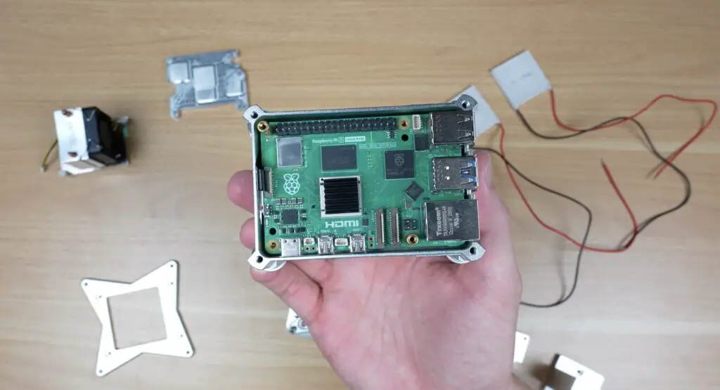
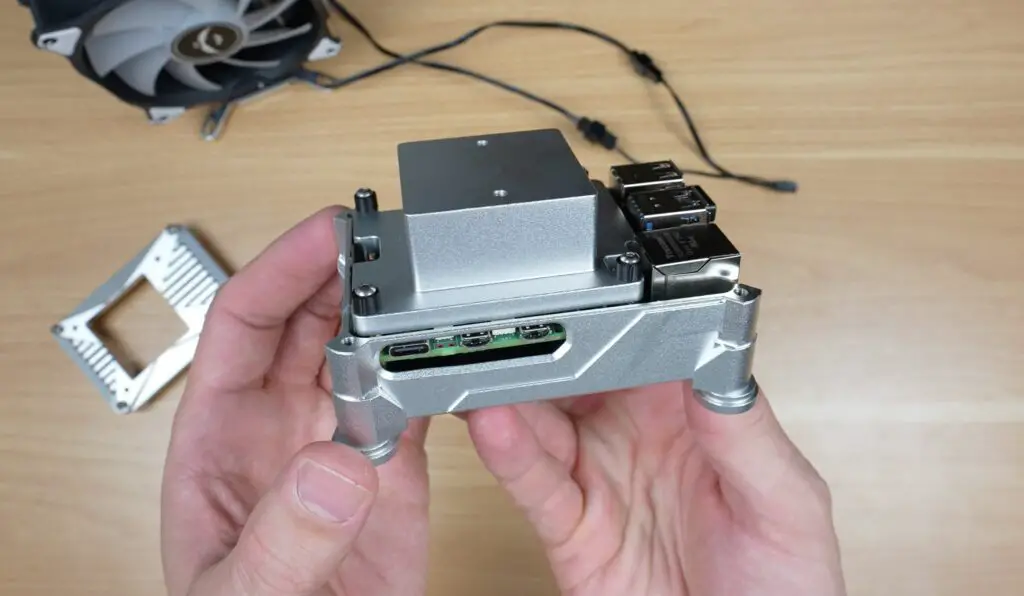
So next, I moved into assembling the basic Pi setup in the case.
Assemblying The Basic Pi 5 Test Setup
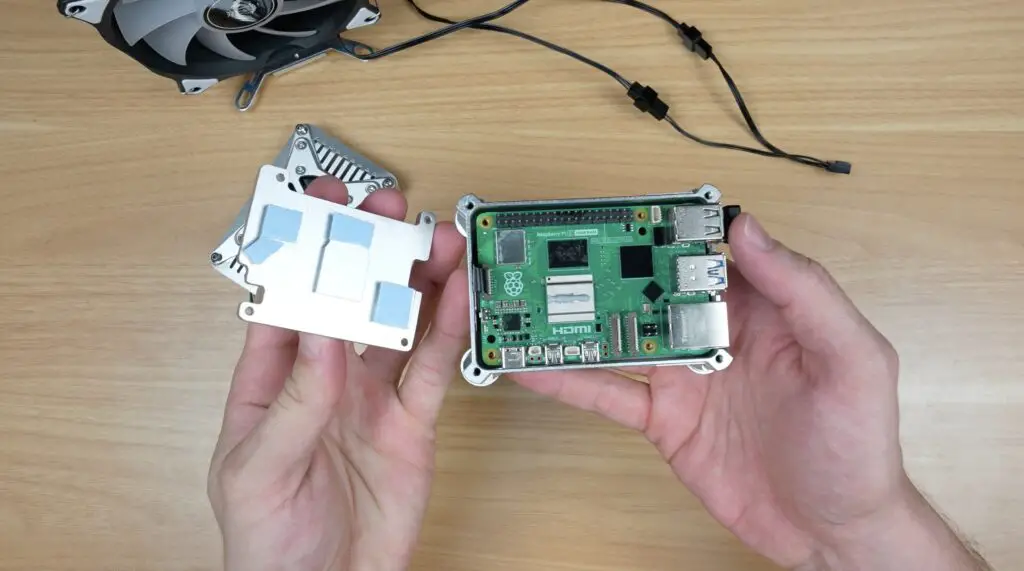
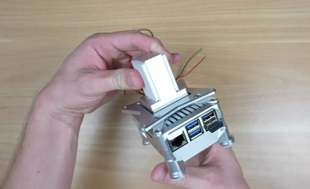
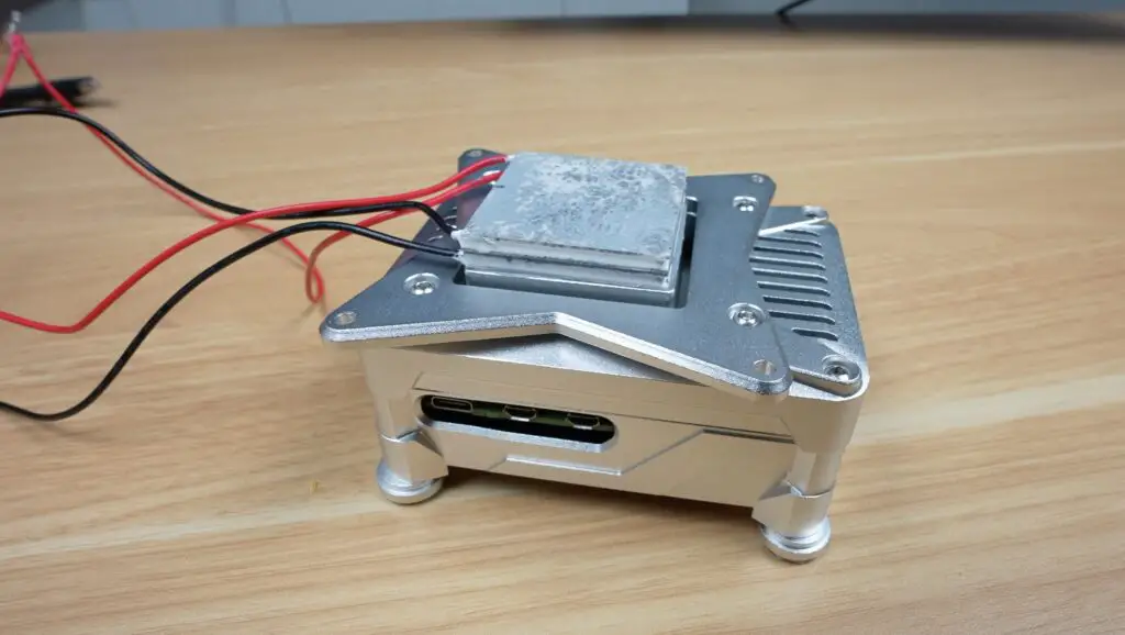
The aluminium enclosure is designed to house an NVMe SSD on a hat underneath the Pi. For this particular build, I’m using a Pimoroni NVMe Base and a Lexar NM620 NVMe SSD, which I’ve preflashed with Raspberry Pi OS Trixie.
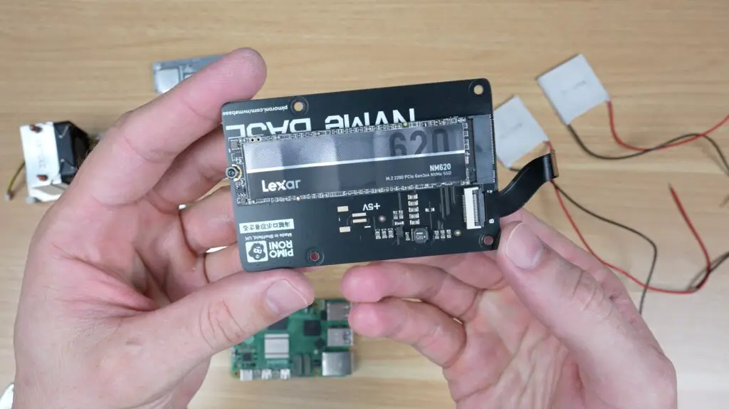
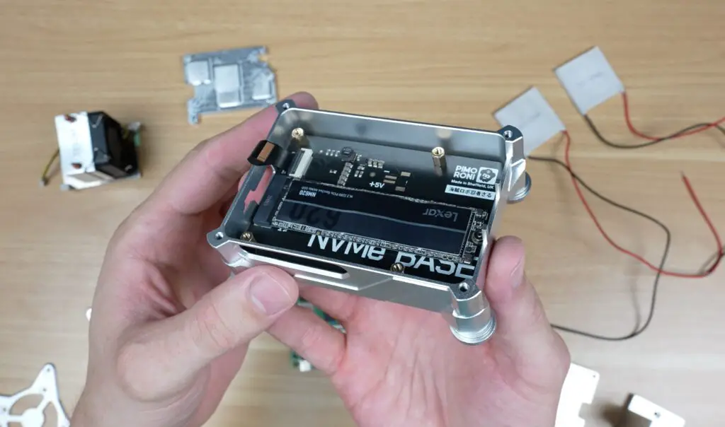
That’s installed onto some brass standoffs screwed into the base.
Next, the Pi is installed above it, and the drive can be connected via the PCIe FPC connector. I’ve used a 16GB Pi 5 for this build as higher memory variants tend to be more stable for overclocking because they’re usually more recently built, although there is still a bit of silicon lottery involved.
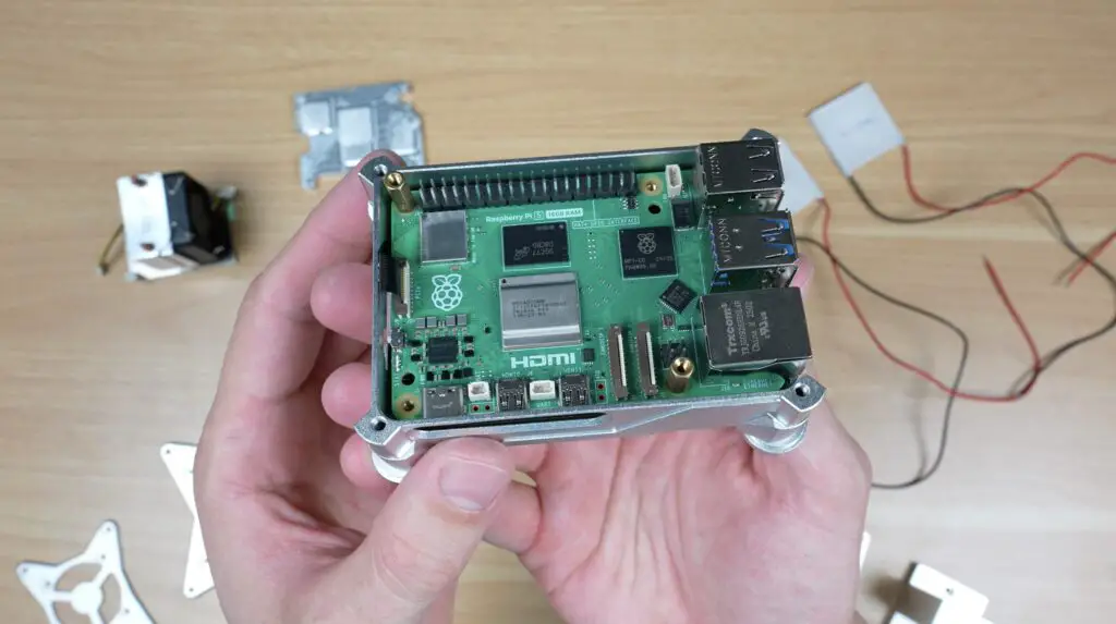
I then trial-fitted the open lid and empty fan cover.
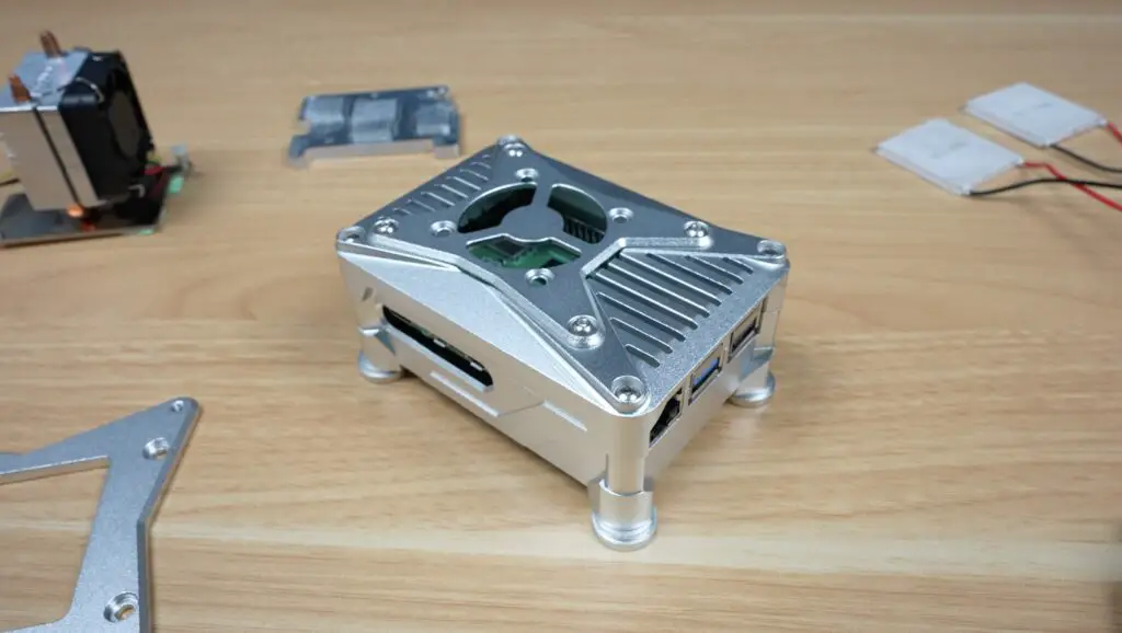
I’m really happy with the end result. I’m actually quite keen on just using this as my main Pi case going forward.
So now let’s move into testing.
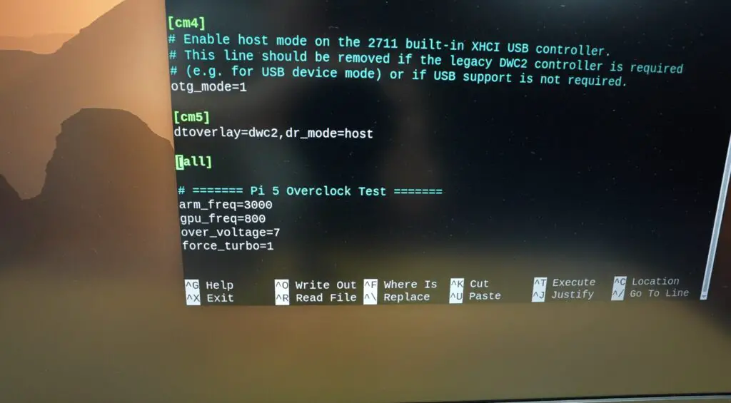
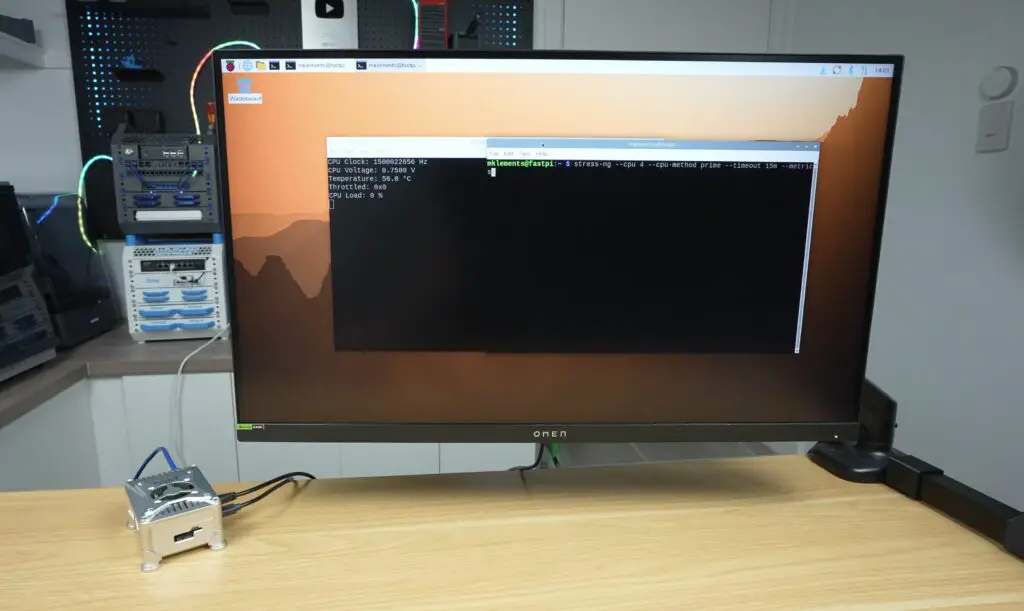
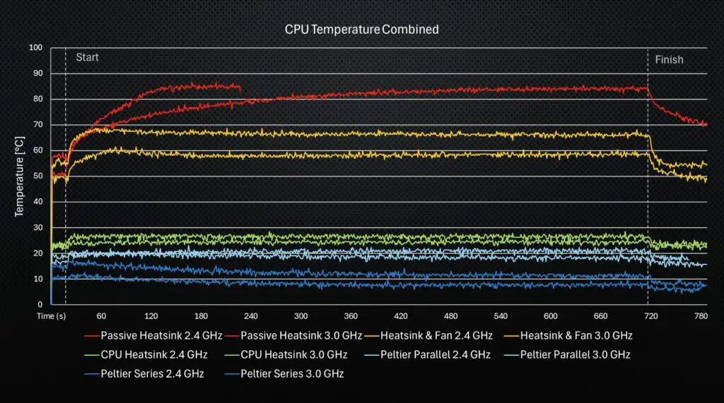
For each setup, I’m going to run the same stress-ng test for 15 minutes, which is usually long enough to fully heat soak the cooler and allow temperatures to stabilise. I’ll do the test at both the stock frequency of 2.4GHz and at an overclocked frequency of 3.0GHz.
To install stress-ng:
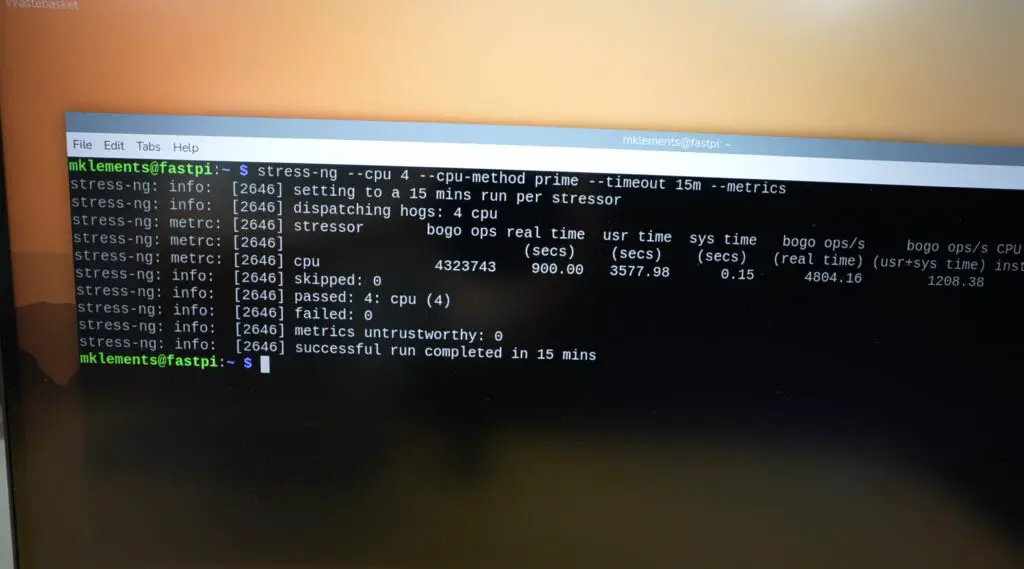
sudo apt install stress-ngThe test that I’m going to be running on each:
stress-ng --cpu 4 --cpu-method prime --timeout 15m --metricsI’ll also do a Geekbench 6 run for the first cooling solution that can make it through the 15-minute stress test at 3GHz without thermal throttling. I’ll then repeat it for the solution that achieves the lowest stabilised temperature.
For each test, I’m only changing the cooler; other than that, I’m keeping the same Pi, NVMe drive, case, power supply and software.
Testing The Pi 5 Cooling Setups
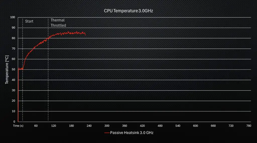
Simple Passive Heatsink
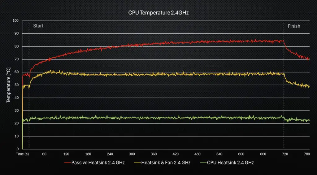
First up, let’s start with a simple passive aluminium heatsink, which I don’t expect to do very well. These are usually fine for light loads, a little above idle, but for sustained loads or any form of overclock, you really need a decent cooler on the Pi 5.
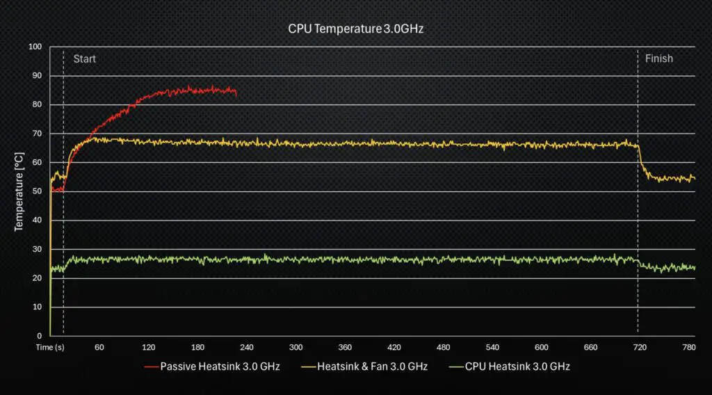
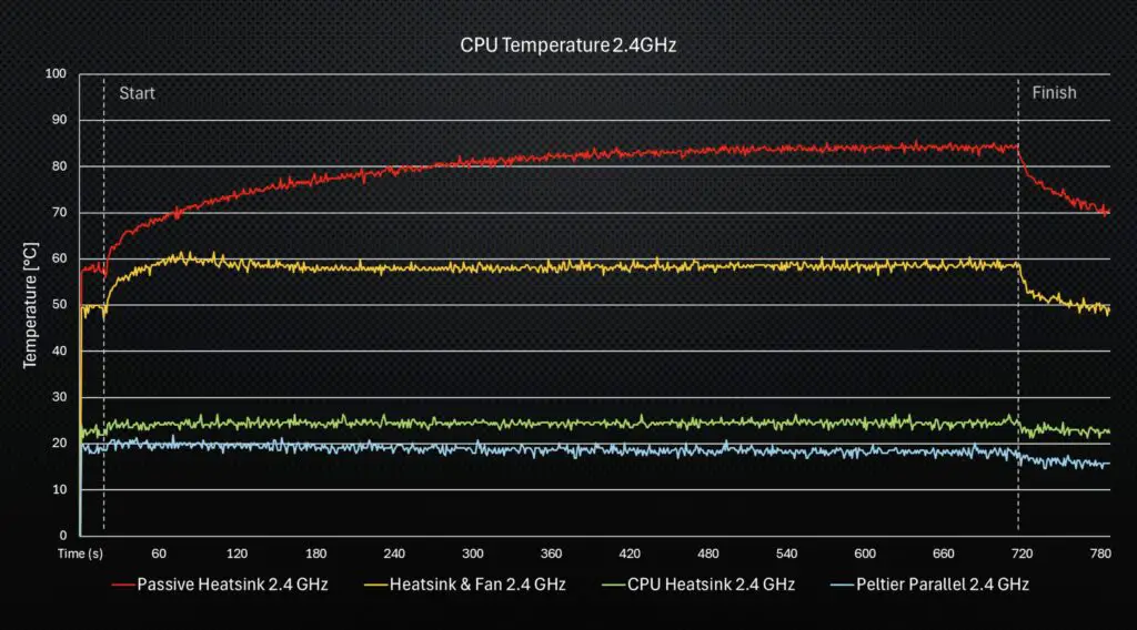
At the stock 2.4Ghz, the CPU temperature started out at 58°C at idle, and it actually managed run for almost five minutes before the first thermal warning. At five and a half minutes, it started thermal throttling. The CPU then stayed at around 82°C for the remainder of the test, but with the CPU running at a reduced frequency.
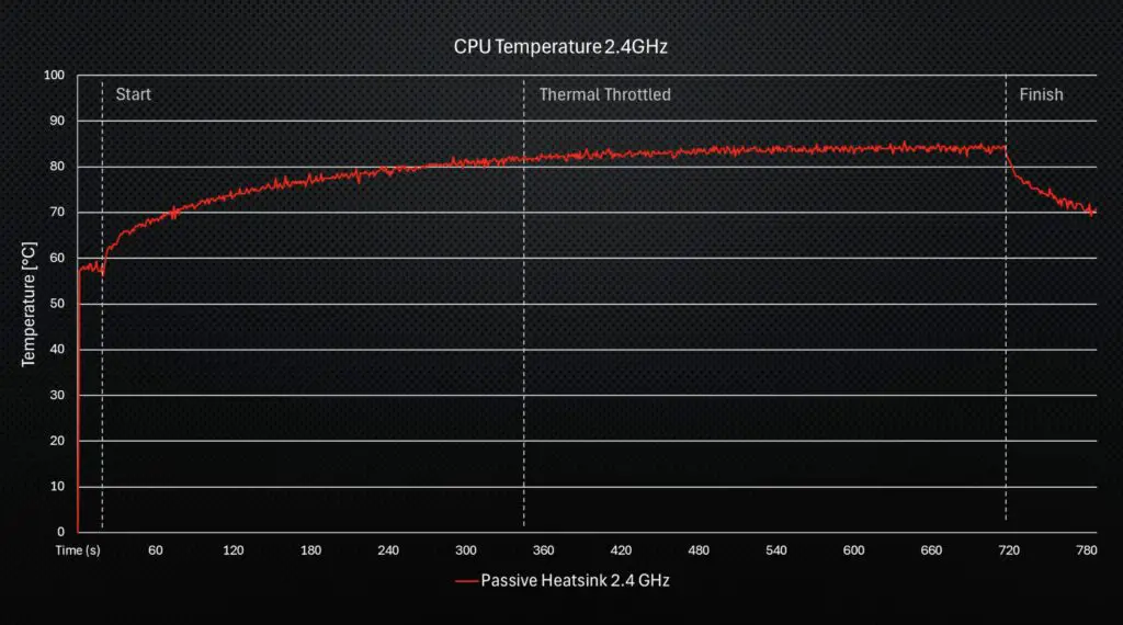
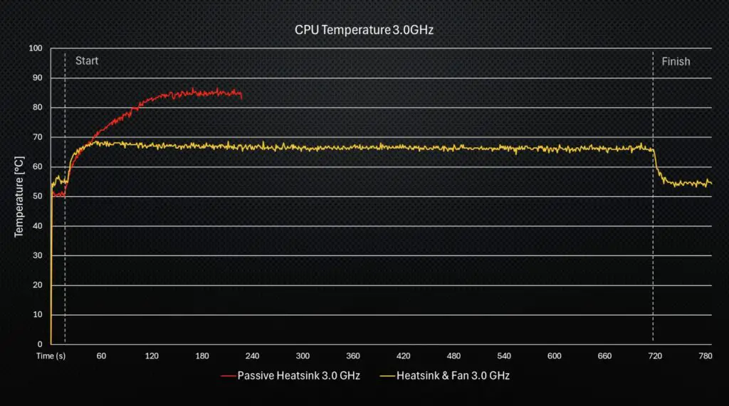
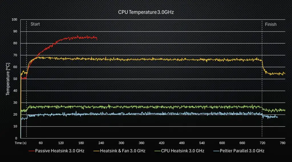
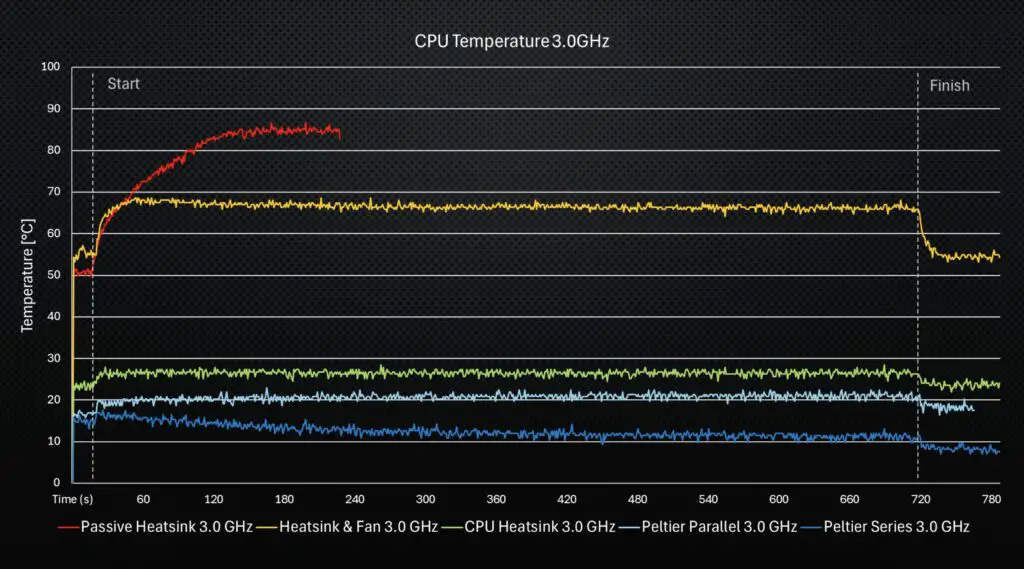
This didn’t bode well for the 3.0 GHz test, but I ran that anyway just for comparison. This test ran for about a minute and a half before thermal throttling, and the CPU temperature then stayed around 85°C, so I stopped the test after three and a half minutes to avoid damaging the Pi.
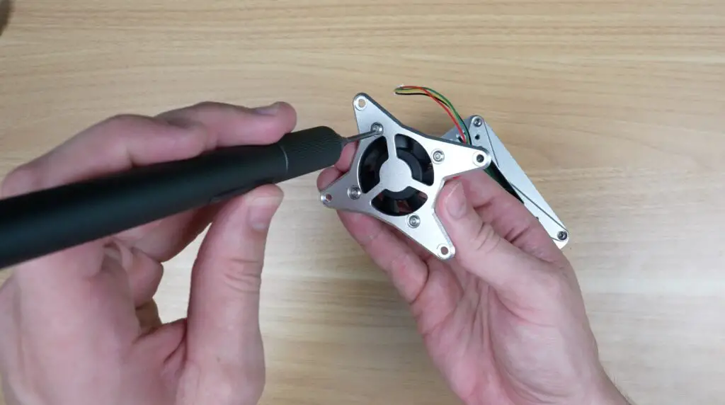
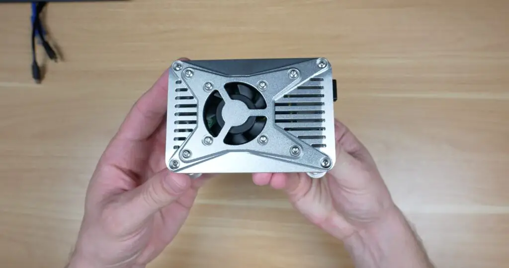
PWM Fan With Simple Heatsink
Next, let’s see how adding a simple PWM-controlled fan to the top of the enclosure helps it out. These fans typically use around a quarter of a watt, so they’re a pretty low-power cooling solution. The one that I’ve installed plugs into the CPU fan port on the Pi, which by default turns on around 50°C and then scales up to maximum speed at 75°C.
At 2.4Ghz, straight away we can see we’ve got a lower start temperature, around 50°C. This run didn’t thermal throttle, and after 15 minutes it had stabilised around 59°C.
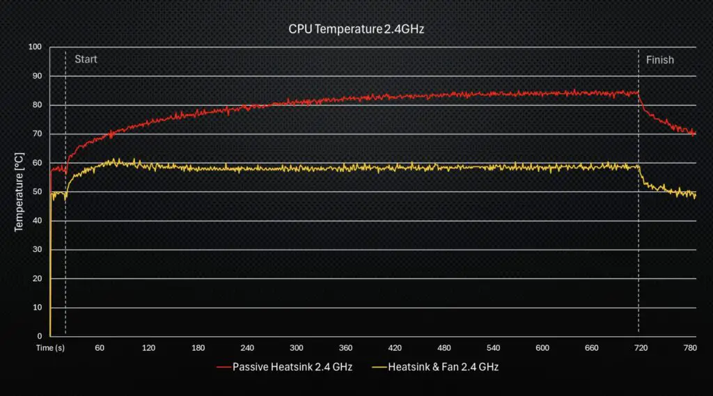
At 3.0GHz, the starting temperature is a little higher at 55°C, and again it didn’t thermal throttle for the duration of the test, with a stabilised temperature around 66°C.
So adding a simple fan is actually quite effective. Interestingly, I assume because of the fan curves, the CPU temperatures actually ran a little hotter in the beginning and then gradually reduced as the fan ramps up, which you can see in the temperature trends.
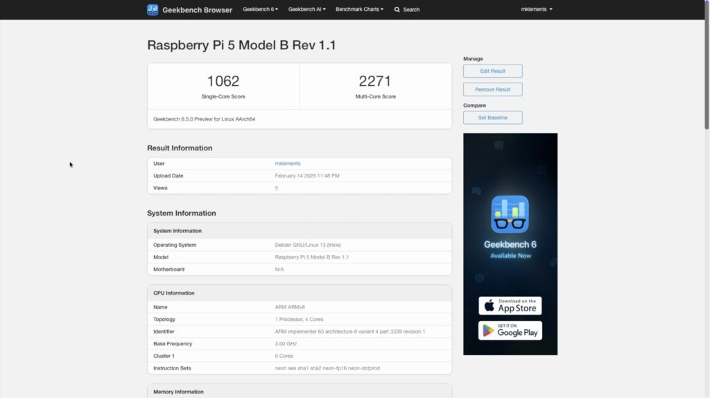
Since this cooling method was able to complete the run, I then ran my Geekbench 6 CPU benchmark. This managed a single-core score of 1,062 and a multicore score of 2,271. These are going to be the scores to beat for the final setup.
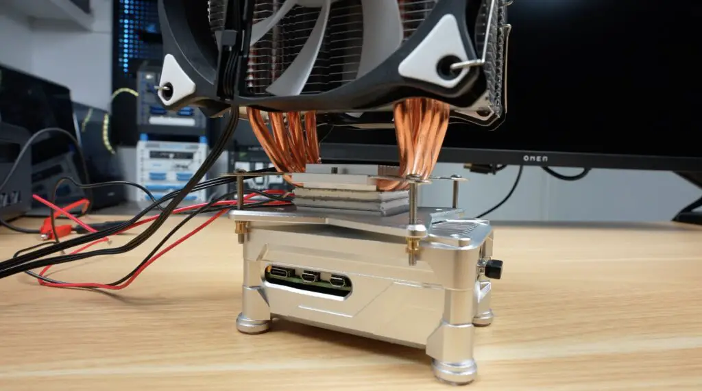
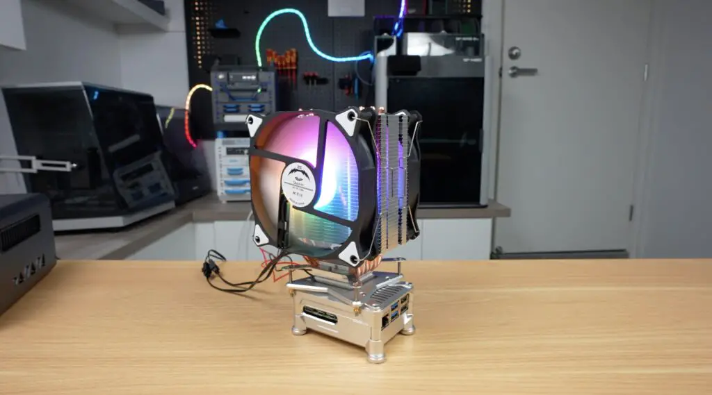
Tower CPU Cooler
Next, I want to move on to our 120mm tower cooler, which is where things start to get ridiculous.
We’ve got this block that now mounts onto the Pi and essentially acts as a large heat transfer block. This removes heat from all of the heat-producing components on the surface of the Pi and transfers it to the base of the tower cooler. I’ve used thermal paste for the CPU, and pads for the surrounding components.
The cooler then bolts onto the top of the case and makes contact with the top surface of this block, which is sized similarly to a PC CPU.
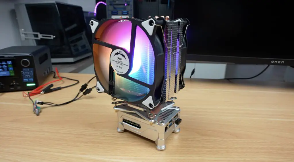
This already looks a bit crazy.
For this setup, I’m powering the fan from a separate 12V power supply, and I’ll do the same for the TECs so that we can see exactly how much power our combined cooling system draws. The dual fans draw 8 watts combined. So about the same as the Pi does at full load.
As you’d expect, this cooler performs really well.
At 2.4GHz, temperatures start out at 23°C and stabilise at just 25°C under full load. So, barely any difference between idle and under load.
At 3.0GHz, the temperature starts out a little warmer at 24°C and stabilises at 27°C under full load.
So both significanlty better than the smaller heatsink we tried first.
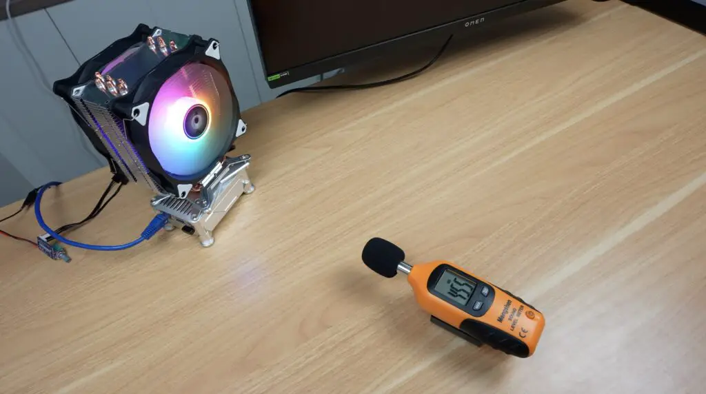
Noise levels are also really low because of the large 120mm fan, although being cheap, unbranded fans, they could be a little quieter.
But now we’re starting to run into a limitation: the cooler can’t cool the Pi below the ambient temperature in my workshop, which is currently around 23°C.
So let’s move on to our active cooling options.
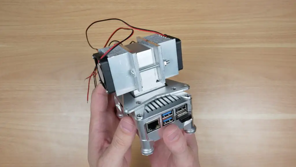
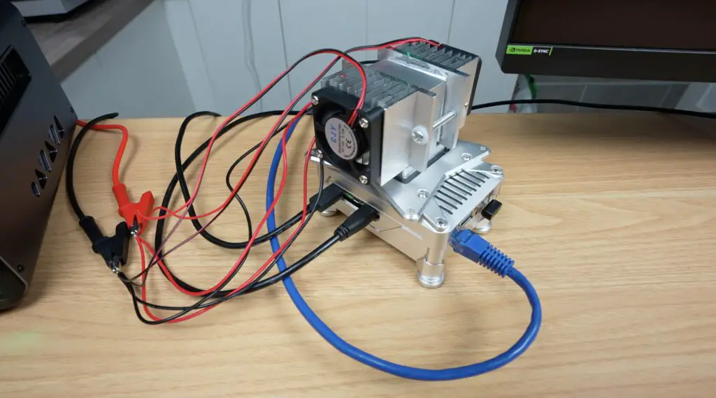
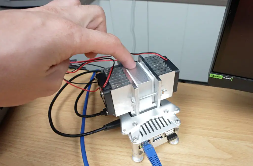
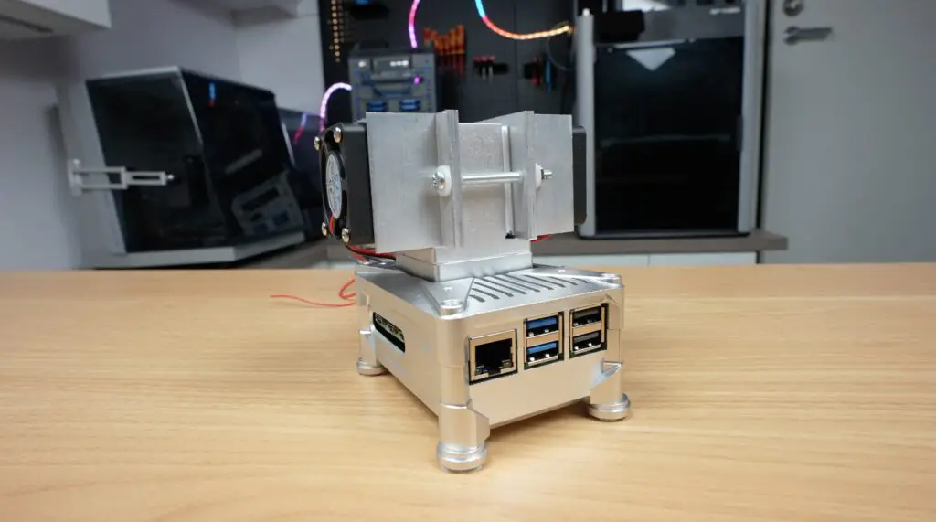
Parallel TEC Cooling Setup
I’ve got two Peltier coolers or TECs, which can do around 30W each. We’ve also got two options to connect them to the Pi.
The first is to connect them in parallel using this adaptor block. A small fan and heatsink then cool the hot side of each cooler.
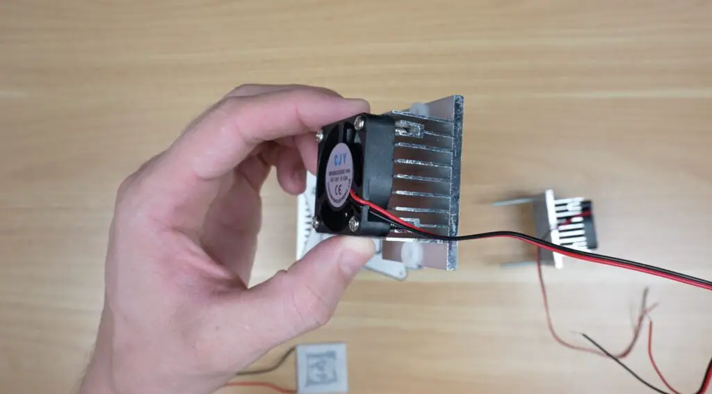
This setup provides roughly 60W of active cooling capacity.
With it booted up at 2.4GHz, we can now turn on the TECs and fans and watch the temperature drop. Because of the potential for condensation, I’m only going to run the TECs for a minute before each test to cool the block down and I’ll let them run for a few seconds after. I don’t want to risk drowning the Pi before I’ve tested all of the options.
After about half a minute, power draw has stabilised at just over 60W, but the results are not as good as I’d hoped for.
On the CPU side, temperatures have dropped under ambient, and on the opposite sides of the coolers, the heatsinks are really hot. The big downside of this arrangement is obviously efficiency. We’re consuming 60W in cooling, while our Pi is only drawing a maximum of around 8W.
With this configuration, at 2.4GHz, we have a starting temperature of 19°C and this stabilises at 18°C under full load. Because of the thermal mass of the large heat sink block, the TECs take a while to cool it down. This leads to our loaded temperature gradually reducing to become lower than the unloaded temperature.
So now, stepping up to 3.0GHz, we have a starting temperature of just 17°C and it stabilises at 21°C under full load. So it’s still running below ambient at full CPU load while overclocked to 3GHz, but for a cooler that’s using over 60W, that’s a disappointing result.
I don’t think these small heatsinks that came with these TECs can actually handle their heat load. We’ve also got the hot air from the heatsinks being blown down onto the Pi enclosure which is adding to the Pi’s heat load.
I did start getting some condensation with this setup on the top of the heat sink, which was probably at around 15 degrees, so it could get much worse with the next setup.
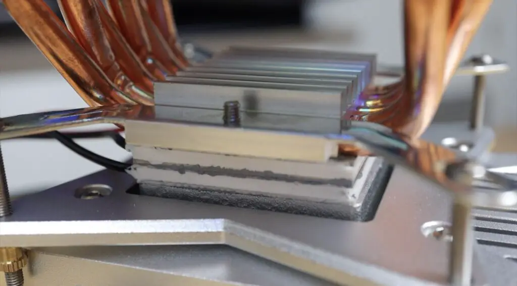
Stacked TEC Cooling Setup
With that test done, the final configuration is to arrange the coolers in series, called cascading. So instead of running the two coolers alongside a central block, I’m now stacking them so that the first cooler cools the second, which then cools the heatsink. On top of the stack, I’m adding the large CPU cooler to keep the hot side of the top TEC cool. This configuration can move less heat as total throughput, but should result in a higher temperature difference between the extreme hot and cold sides.
I think that this setup will have the highest potential cooling performance, but it also has the highest complexity and there’s the risk of condensation forming if temperatures drop below dew point, which is currently around 14°C in my workshop.
With this setup, I initially pushed the power draw up to 70w, but I managed to crank it up a bit more, up to 82w because the CPU cooler performed much better than the small heatsinks.
With our most extreme cooling solution, at 2.4GHz, we have a starting temperature of just 10°C, and this stabilises at 8°C under full load.
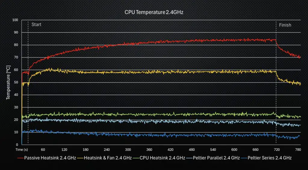
And finally, stepping up to 3.0GHz increases the starting temperature to 15°C, and it stabilises at 11°C under full load. So we’re now running at over 13°C less than ambient at full load and overclocked. And we also have a pretty ridiculous-looking Pi.
Condensation is already quite bad, you can’t see it on the outside of the enclosure, but you can see droplets have formed on the cold heat block. The Pi is still running, so I decided to try my Geekbench run. This managed a single-core score of 1,066 and a multi-core score of 2,311.

So slightly better than with the fan cooler, but this is less than a 4% difference, so for the additional power draw, it’s definitely not worth it.
Final Thoughts On My Cooling Setups & Test Results
Putting the logged results side by side, we can see some interesting trends.
Passive cooling does ok for short bursts, but eventually heat saturates the heatsink, and it becomes ineffective.
Forced air cooling using a small 30-40mm fan provides the best balance of performance, simplicity, and power efficiency, and you can PWM control it to manage noise too.
The tower cooler delivers excellent sustained performance and allows higher overclocks, although it looks pretty ridiculous doing so.
And while the Peltier setups can achieve lower temperatures, they require significantly more power and introduce a lot more complexity into the system.
The stacked TEC configuration produced the lowest temperatures overall, but at the expense of power draw that’s almost 10 times that of the Pi it’s cooling.
So… was any of this actually necessary?
Absolutely not.
As you can see from the Geekbench results, there was only a marginal improvement in performance between the simple small fan and heatsink and the stacked peltier arrangement that I tried at the end, at the cost of over 80 watts increase in power draw.
This is also supported by the stress test results. You can see at the end of the fan run that the Pi had performed 4,323,743 bogus operations in the 15-minute period, and with the stacked peltier test this only went up by 42 operations. This is less than a thousandth of a percent improvement.
As long as your cooling solution can stop your Pi from thermal throttling, at whatever frequency you’re running, then any additional cooling capacity doesn’t really provide any benefit.
Realistically, a good heatsink and fan or a small tower cooler is probably the sweet spot for most people. In fact, in my past tests, the $5 active cooler that was designed for the Pi 5 does a pretty good job cooling an overclocked Pi too.
In any case, experimenting with TEC cooling was both fun and interesting, and it shows the advantages and the limitations of active cooling on small computing platforms.
If you’d like to see more extreme cooling experiments or if you’ve got ideas for other completely unnecessary upgrades I should try, let me know in the comments section below.