Today we’re going to be taking a look at the Orange Pi 5 Pro. This is a new SBC from Orange Pi that is based on the Rockchip RK3588S SOC. The RK3588S is largely similar to the RK3588, with the main difference being a reduction in PCIe lanes from 4 to just 1.
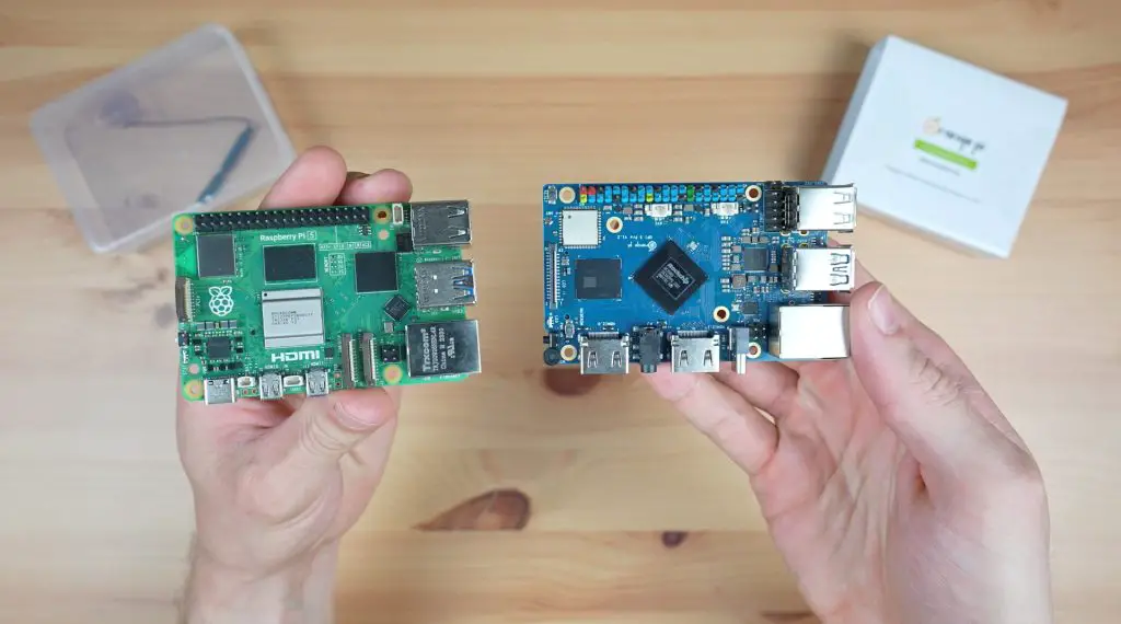
Given the form factor, IO and port layout, the Orange Pi 5 Pro is clearly targeted as an alternative to the Raspberry Pi 5. So let’s see how it’s price, performance and usability stack up.
Here’s my video of the Orange Pi 5 Pro, read on for the written review:
Where To Get The Orange Pi 5 Pro
Equipment Used
- Infiray P2 Pro Thermal Camera – Buy Here
- Power Meter USB C Cable – Buy Here
- Video Capture Box – Buy Here
Unboxing & First Look At The Orange Pi 5 Pro
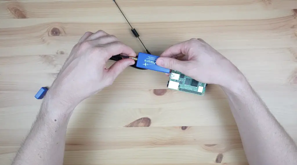
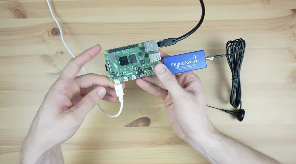
The Orange Pi 5 Pro comes in the usual transparent plastic sleeve with an Orange Pi branded sleeve around it. Within the case, the 5 Pro is protected by an anti-static sealed bag. It includes a WiFi antenna but I’m going to remove this for testing as I’ll be using a wired connection.
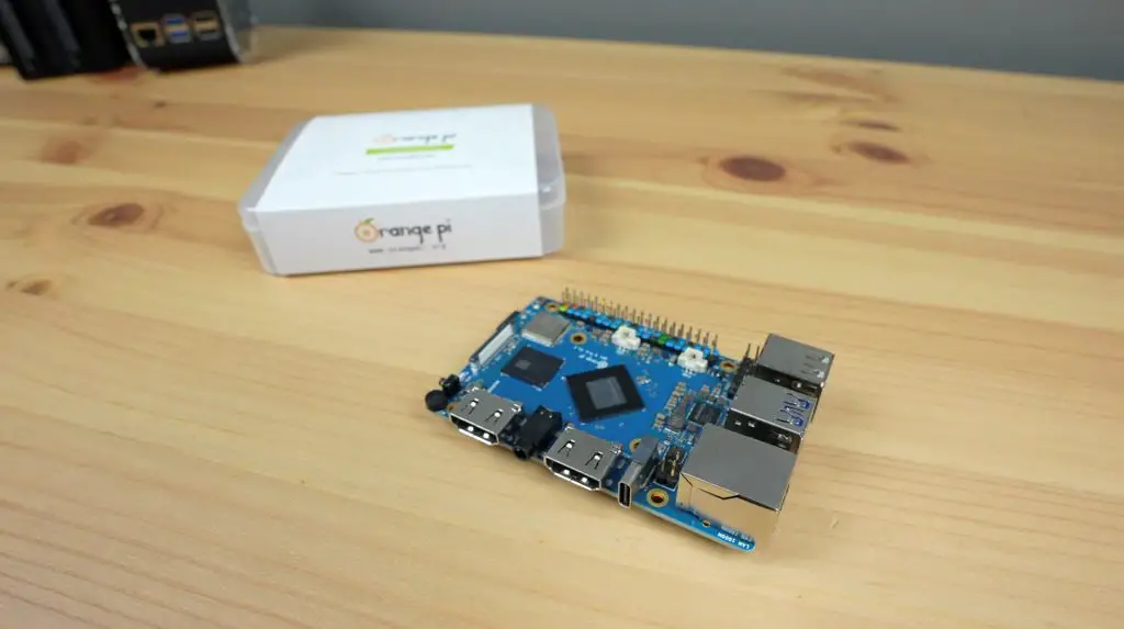
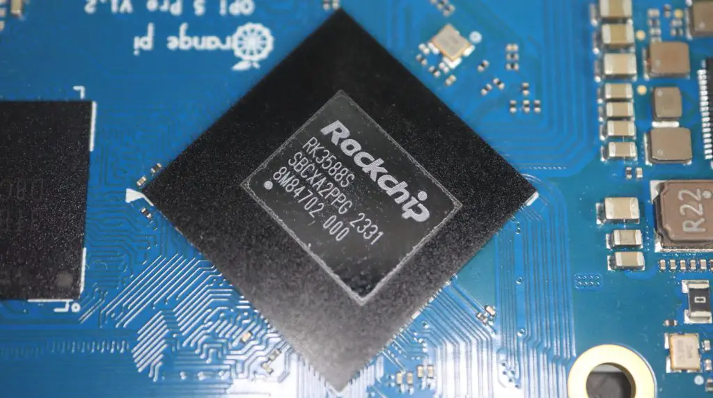
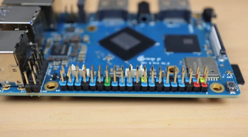
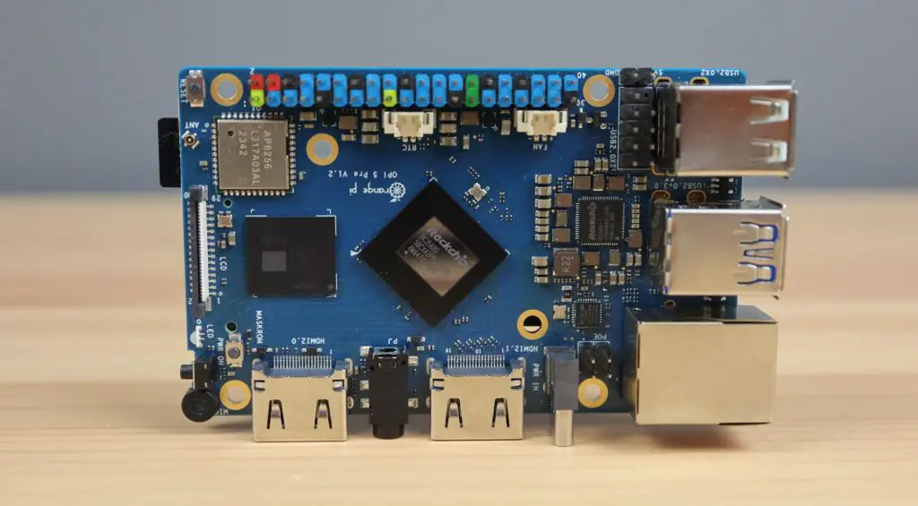
Taking a look around the board, the RK3588S processor is in the middle. This is an 8-core, 64-bit processor that consists of a 4-core Cortex A76 processor running at 2.4GHz and a 4-core Cortex A55 processor running at 1.8GHz. In addition to this, it’s got an Arm Mali G610 GPU. So we should get really good performance from it with double the CPU cores of the Raspberry Pi 5, although four cores are running at a lower clock speed.
Alongside the processor is the RAM chip. The Orange Pi 5 Pro comes in a 4GB, 8GB and 16GB variant, all with LPDDR5 RAM, which is a step up from the LPDDR4 RAM on the non-pro version of the Orange Pi 5.
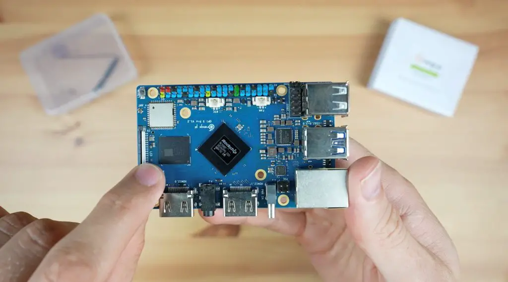
Above that is the WiFi 5 and Bluetooth 5 chip, with a DSI port alongside it.
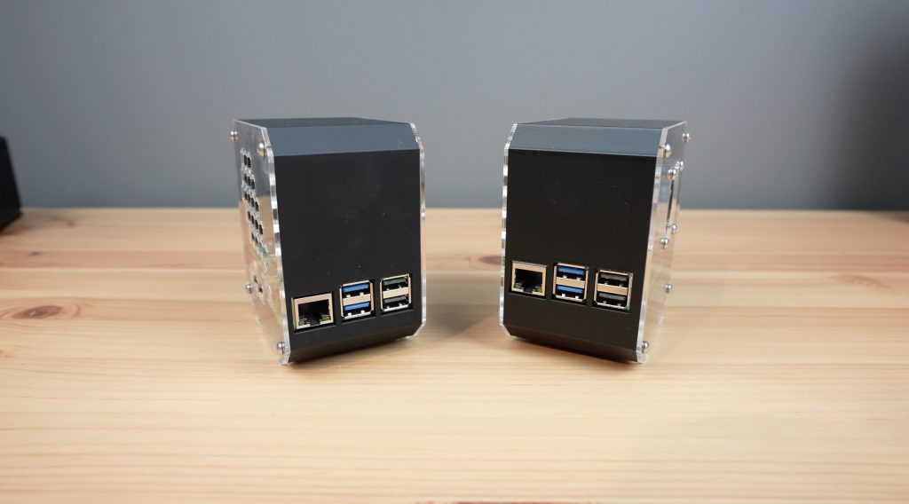
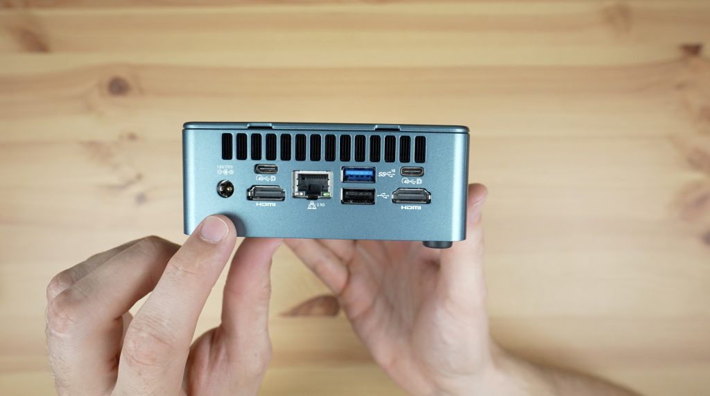
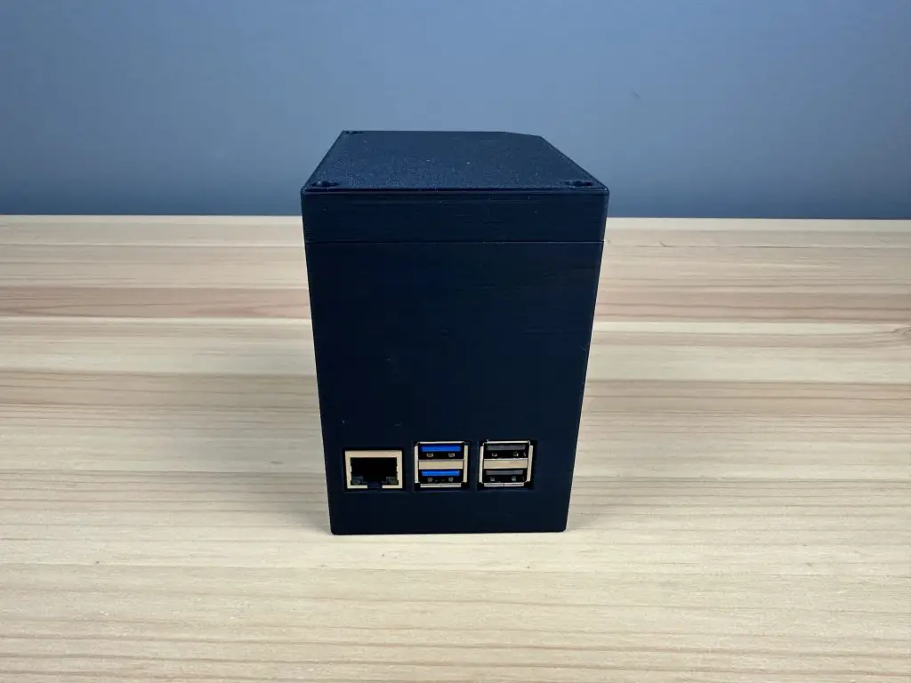
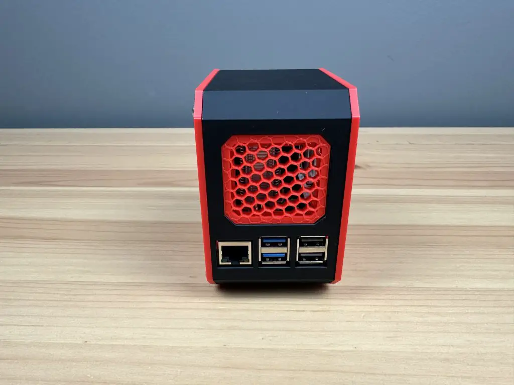
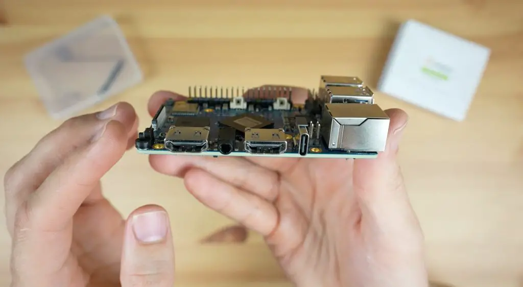
Similar to the Raspberry Pi 5, the Orange Pi 5 Pro, has a Gigabit Ethernet port on one side alongside four USB ports. Notably, three of these are USB 2.0 and only one is USB 3.0, unlike the Raspberry Pi’s two USB 3.0 ports.
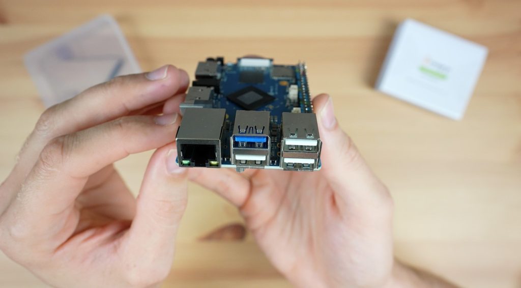
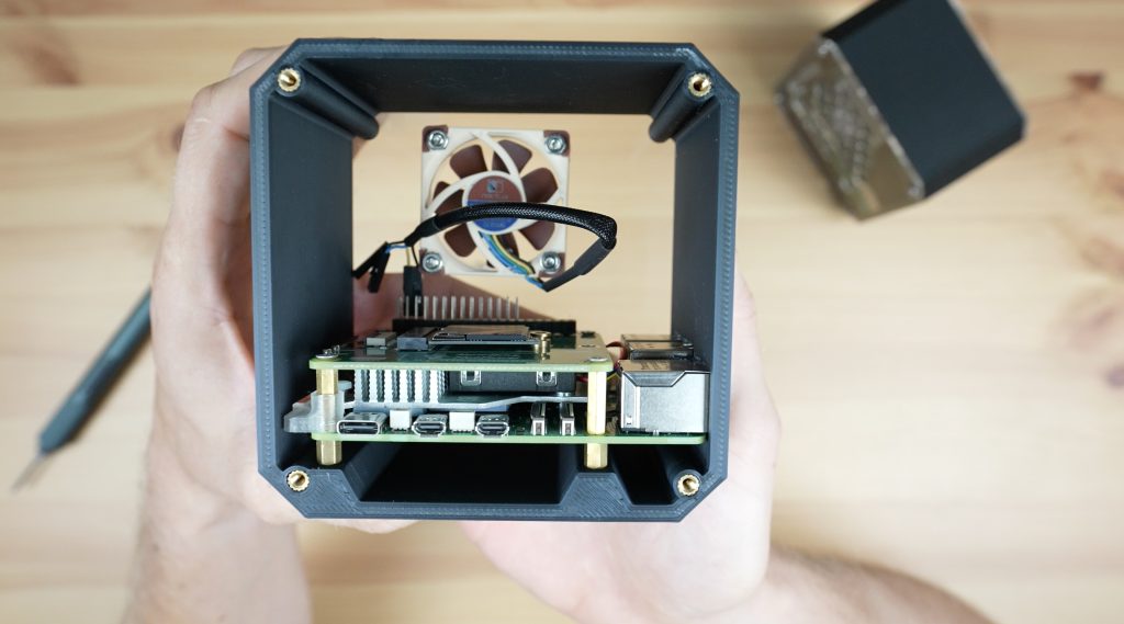
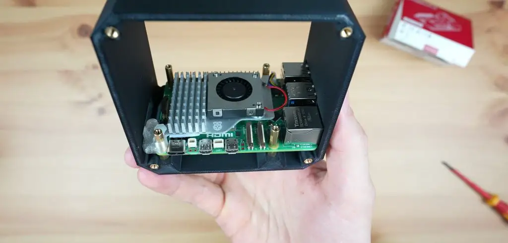
They have also included a header for additional USB 2.0 ports behind the physical ports, which could be useful for building the Orange Pi 5 Pro into an enclosure.
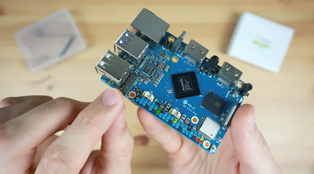
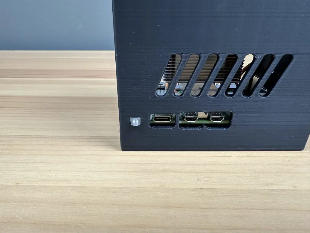
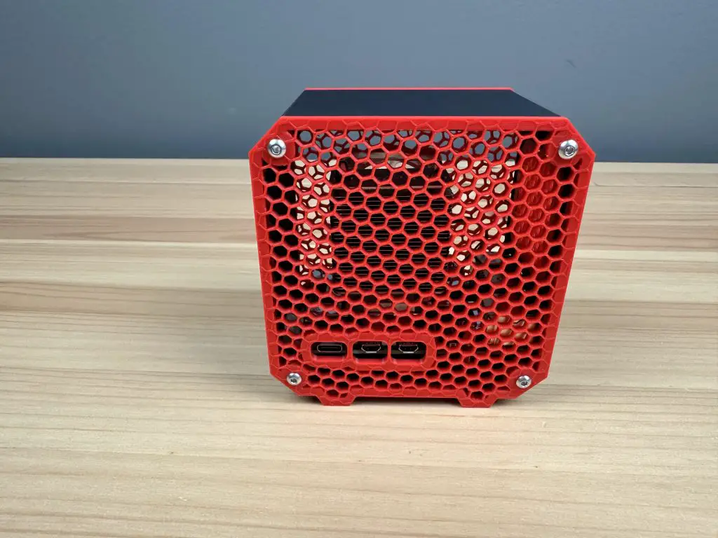
Along the other side is an HDMI 2.0 port, an audio port, an HDMI 2.1 port and a USB C power port. The HDMI 2.1 port can do up to 8K 60 and the HDMI 2.0 port up to 4K 60. I like that they’ve made space for full-size HDMI ports, I don’t really like how fragile the micro HDMI ports on the Raspberry Pi 4 and 5 are, often requiring adaptors or special cables to plug into them rather than commonly available full-size HDMI cables. Interestingly, they’ve chosen to keep the audio port since the Raspberry Pi 5 did away with it.
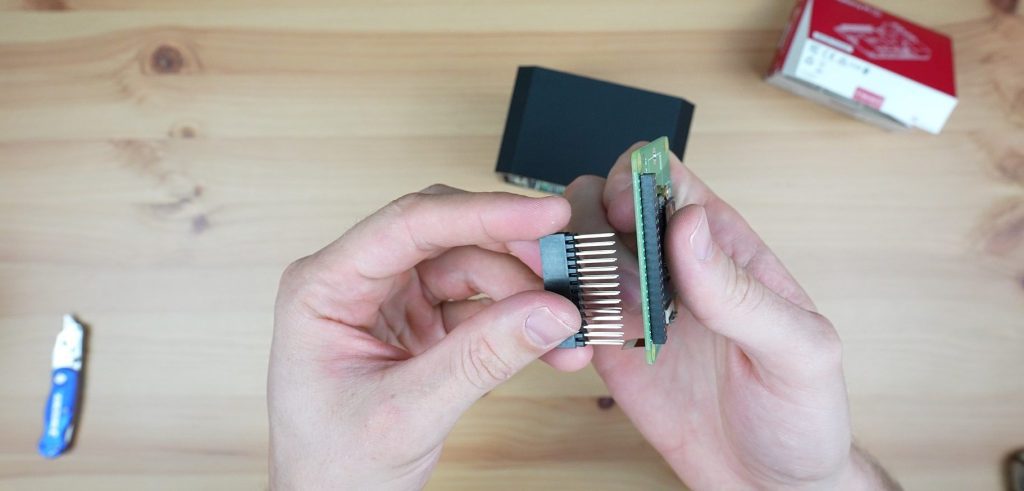
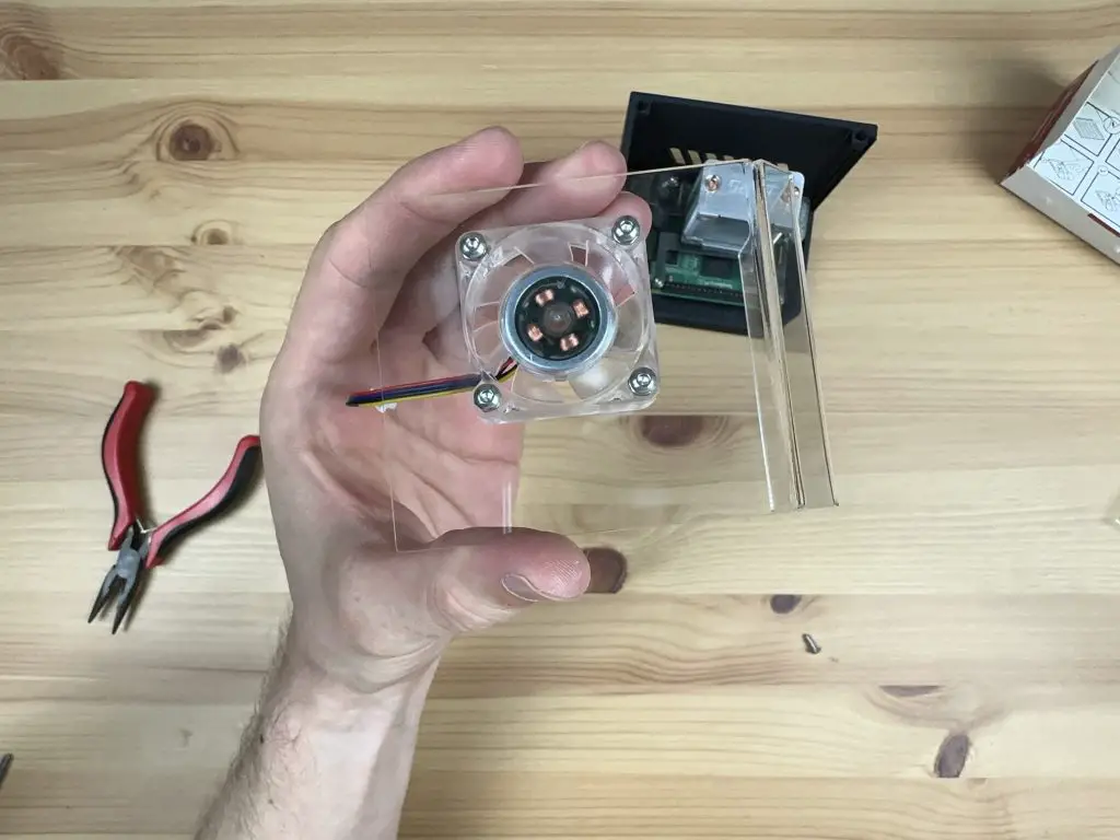
On the opposite side is a 40-pin GPIO header which follows the same pinout as the Raspberry Pi boards, it’s also colour-coded which makes it a bit easier to locate the 5V, 3.3V and ground pins. Next to the pins are a 5V fan connector and an RTC connector.
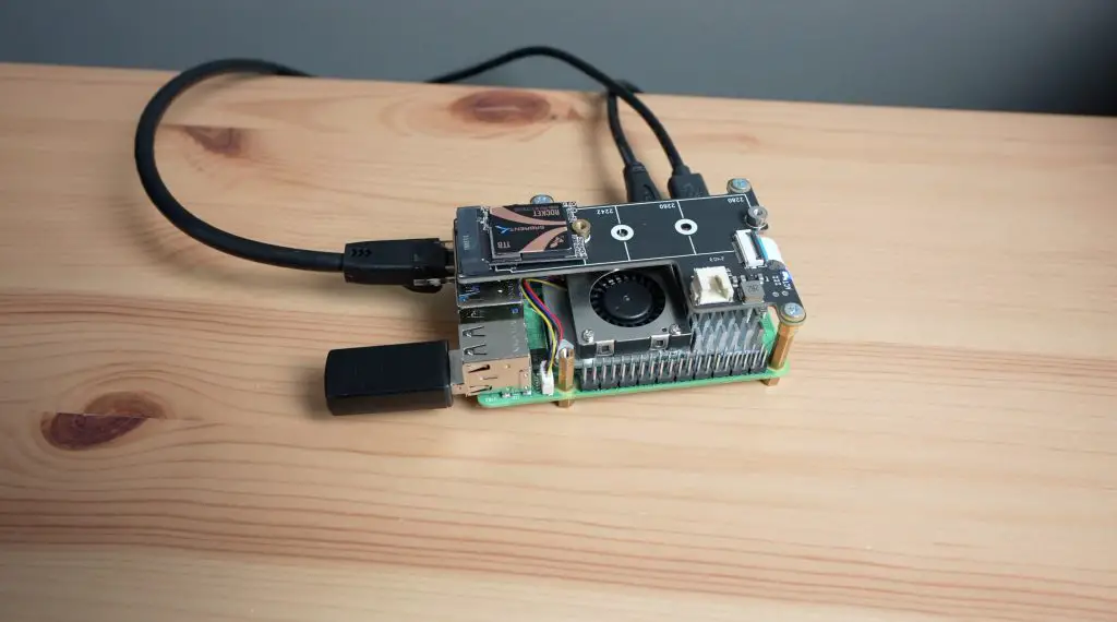
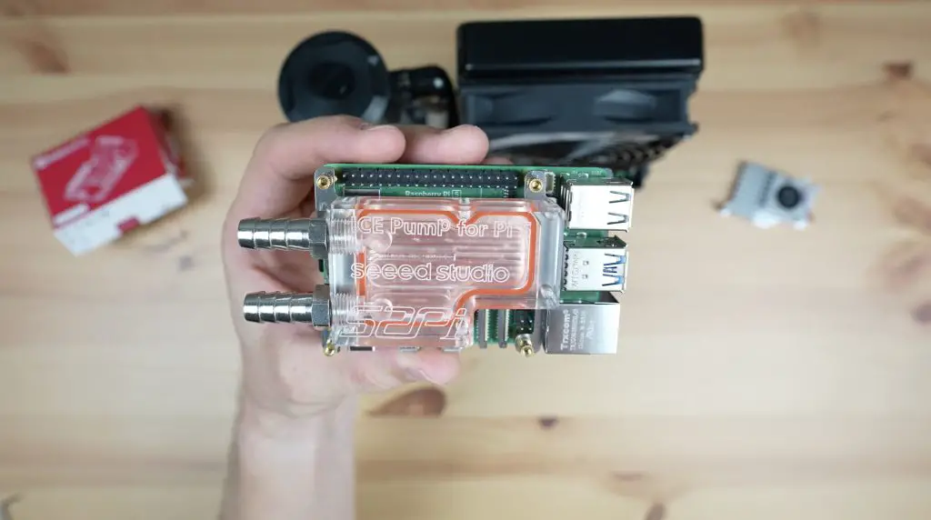
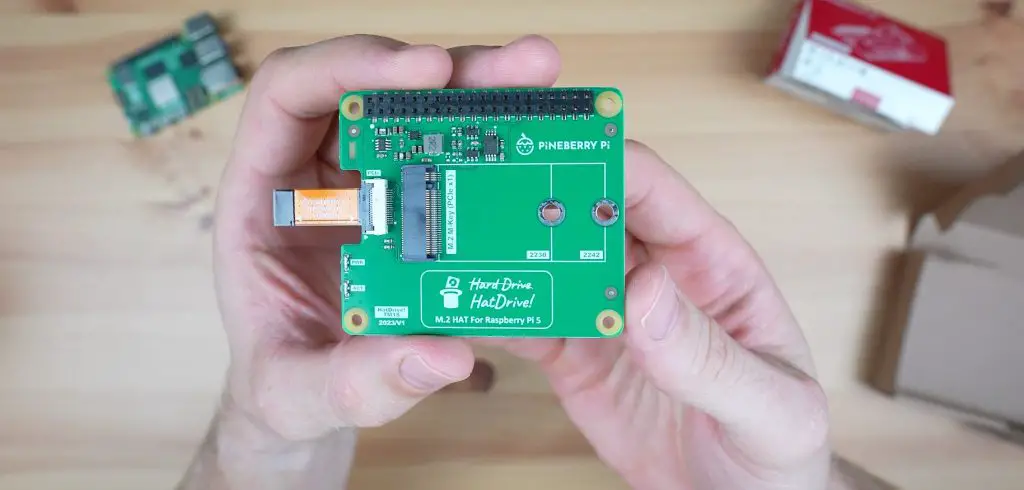
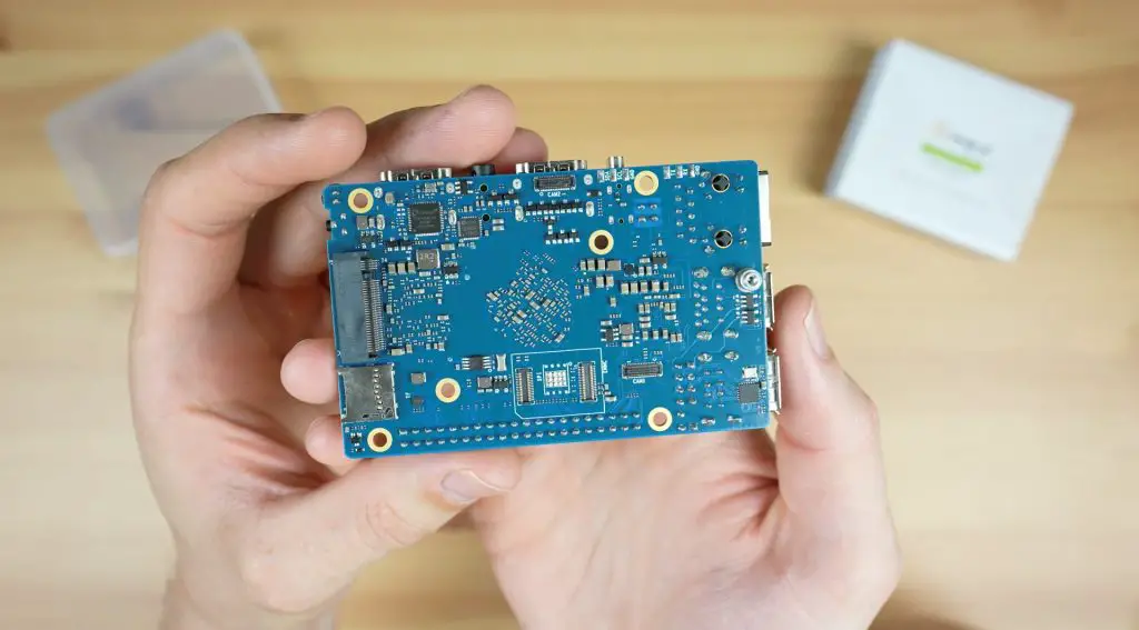
Underneath the board is a prominent M.2 M-key port which allows you to connect an NVMe SSD to it. This is only a PCIe gen 2 x 1 port, so won’t be that fast by today’s standards. It’s also got a connector for additional eMMC storage, a microSD card slot and two camera ports.
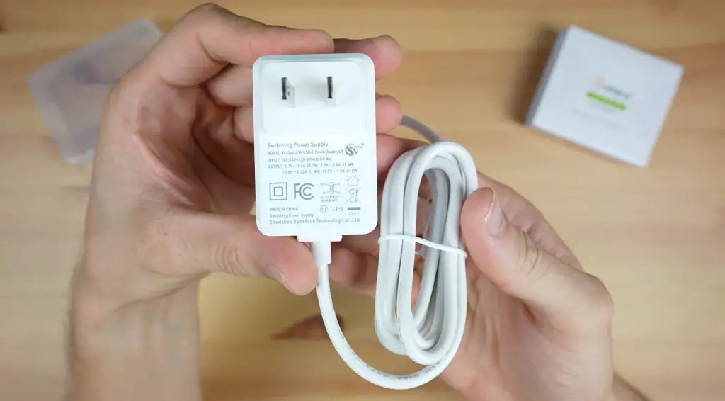
To power the Orange Pi 5 Pro, you can get a 5V 5A USB C power supply from Orange Pi’s Aliexpress store. This has the same specs as the Raspberry Pi 5’s official power supply so you can use one of those too.
So that’s an overview of the hardware. As you can see, the IO is somewhat limited due to the single PCIe lane on the RK3588S, but you’ve still got a range of options and support for an NVMe drive without an adaptor. Hopefully, the power of the CPU and improved RAM will make up for some of the IO limitations. So let’s get it booted up to find out.
Operating System Options For The 5 Pro
Like with other Orange Pi boards, they have a number of operating system images available to run on the 5 Pro, including the usuals like Ubuntu, OpenWRT, Debian and Android. The main OS that they want you to run on it is called Orange Pi OS and they also have a couple of options for this, including an Arch Linux and Android version as well.
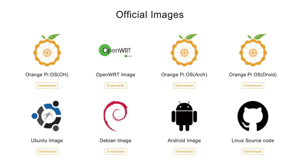
At the time of writing this review, not all of the above images are available, but I’ll be using the Debian image for testing as this is what I’ve tested other SBCs on. This allows the results of my other tests to be a bit easier to compare to.
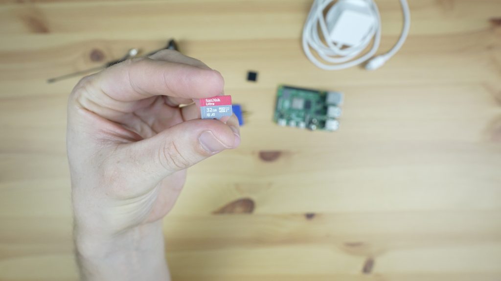
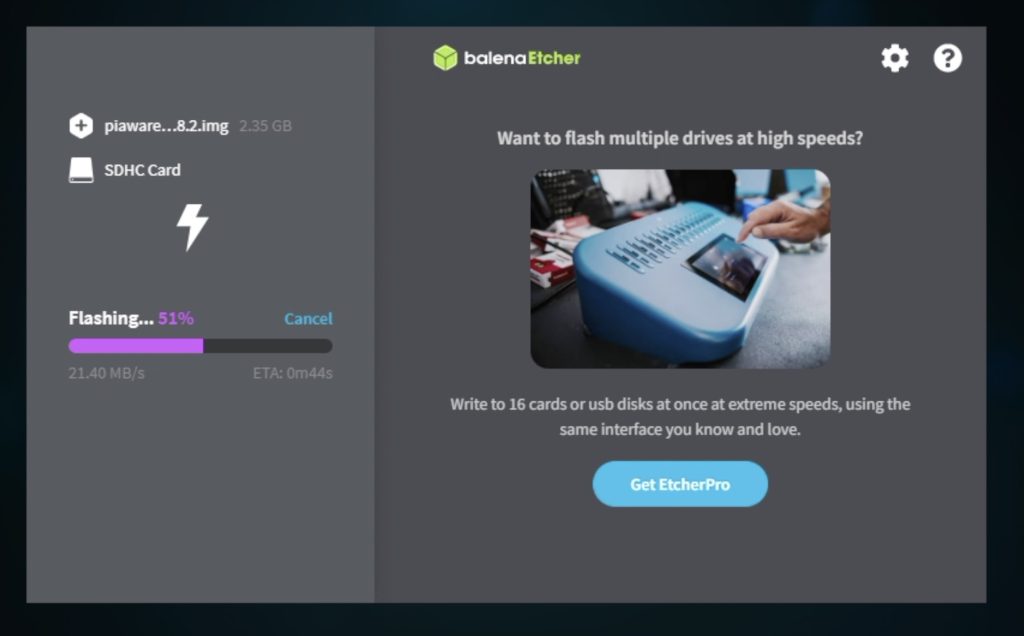
Installing an operating system is really simple. You just download the relevant image from their website and then flash it onto a microSD card using a utility like Balena Etcher.
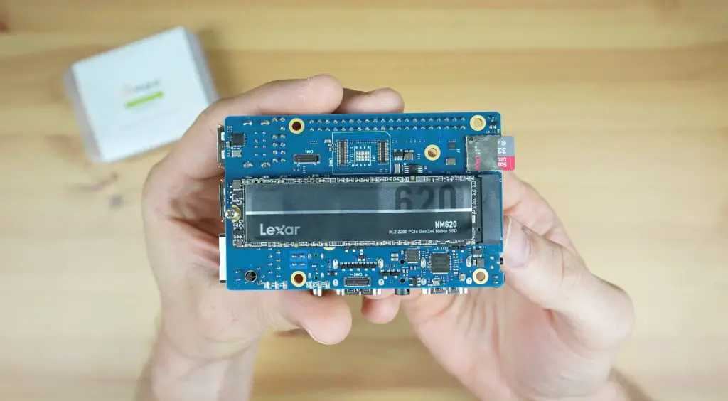
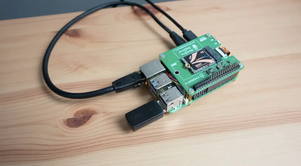
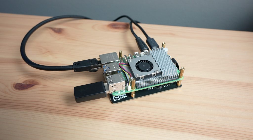
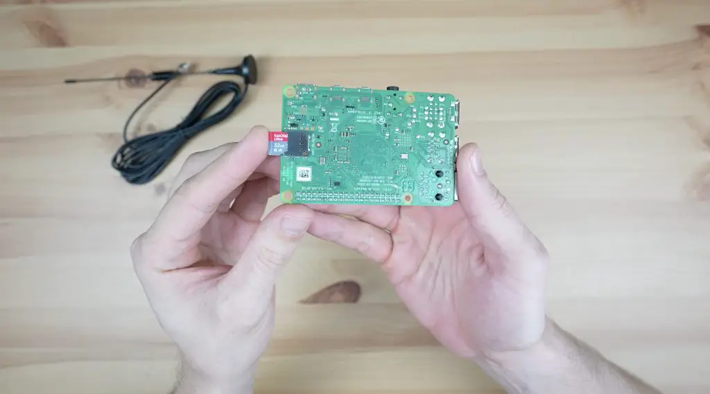
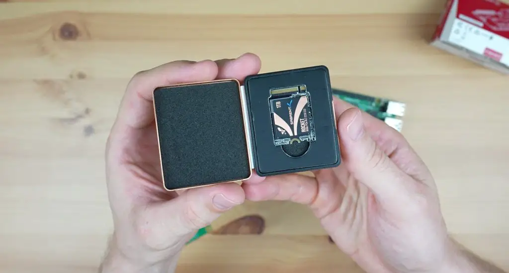
I’ve got the OS flashed onto a microSD card which the Orange Pi 5 Pro will be booting off and I’ve also added an NVMe storage drive to do a benchmark on as well.
Testing The Orange Pi 5 Pro’s Performance
I’m going to test the Orange Pi 5 Pro in the same way I usually test SBCs, by running the following tests:
- Video playback at 1080P
- Video playback at 4K
- Sysbench CPU benchmark
- NVMe drive speed test
- Measure power consumption
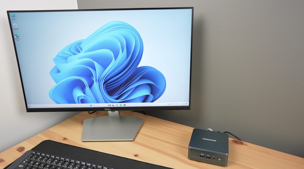
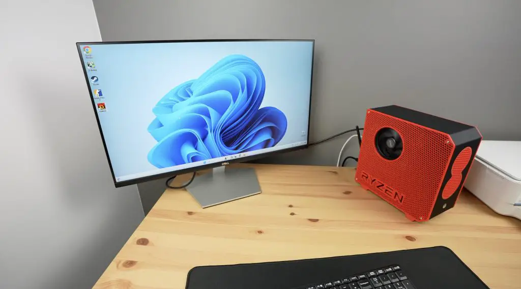
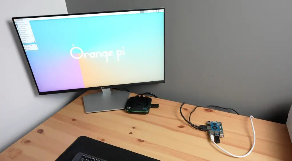
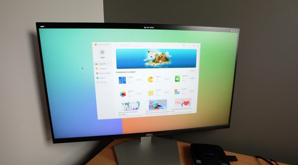
The first boot on a new operating system takes a little longer than subsequent boots but we’re still on the desktop in under a minute.
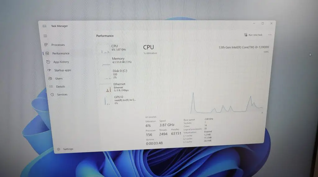
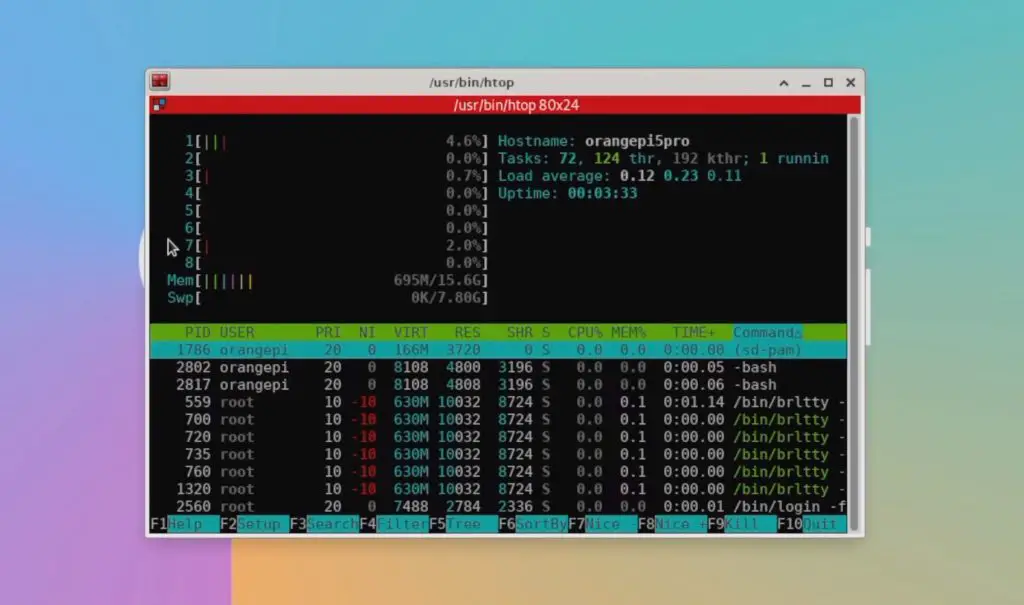
If we open up HTOP, we can see we have our 8 processor cores listed. They’re all relatively idle without any applications running, and we can see our 16GB of RAM.
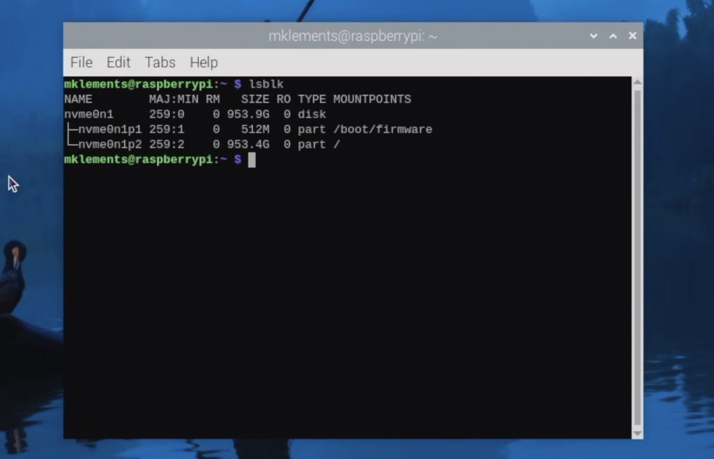
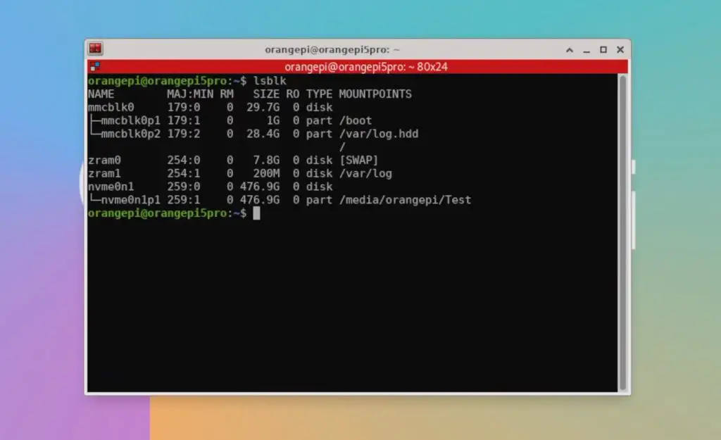
We can also see that our NVMe drive is connected, which is also apparent through the desktop icon.
Video Playback At 1080P and 4K
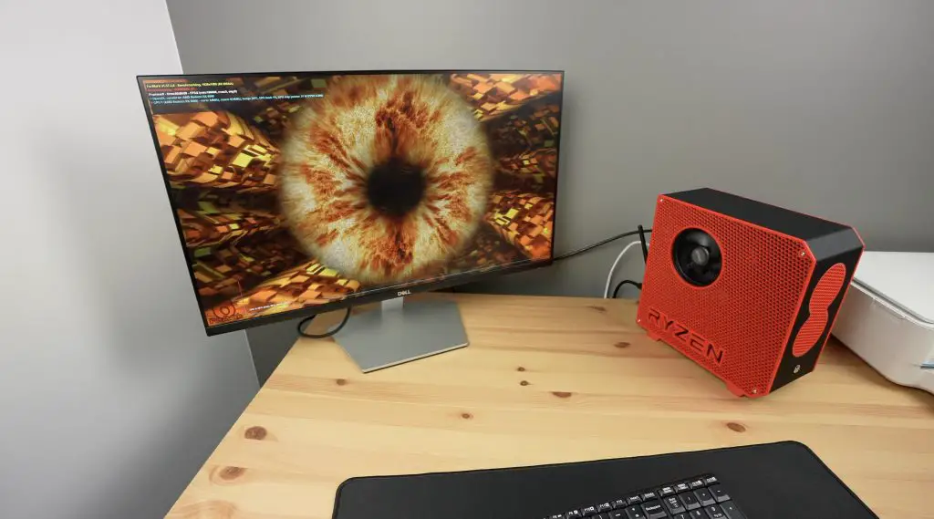
First, let’s try playing back a YouTube video in the default browser Chromium. I’m going to do this at 1080P and then at 4K.
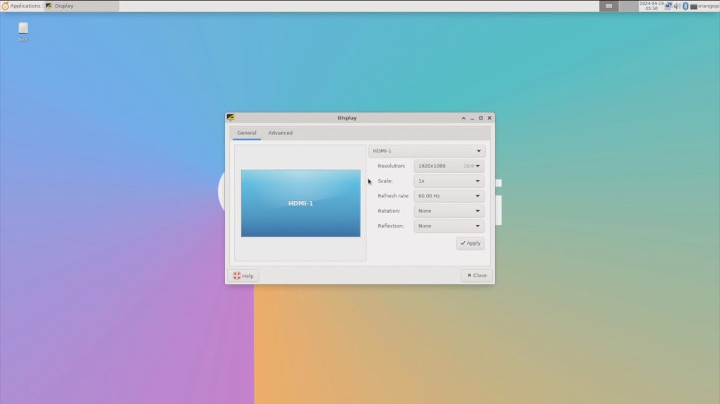
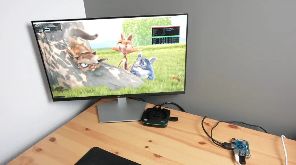
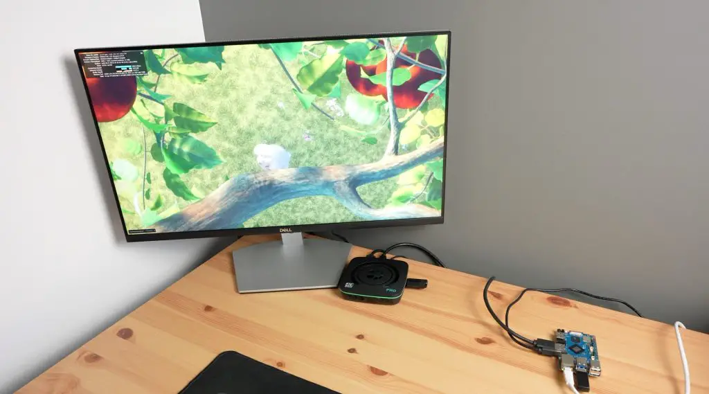
We’ll set the display resolution to 1080P. Then let’s open up the browser, go to YouTube and open up Big Buck Bunny. I’ll set the playback resolution to 1080P and then open up stats for nerds.

Video playback in the window drops a few frames in the beginning but after that is near perfect.

Playback is ok in full screen, but it does drop a couple of frames every so often which is noticeable and does become annoying. You can see example video clips in my video linked at the beginning of the post.

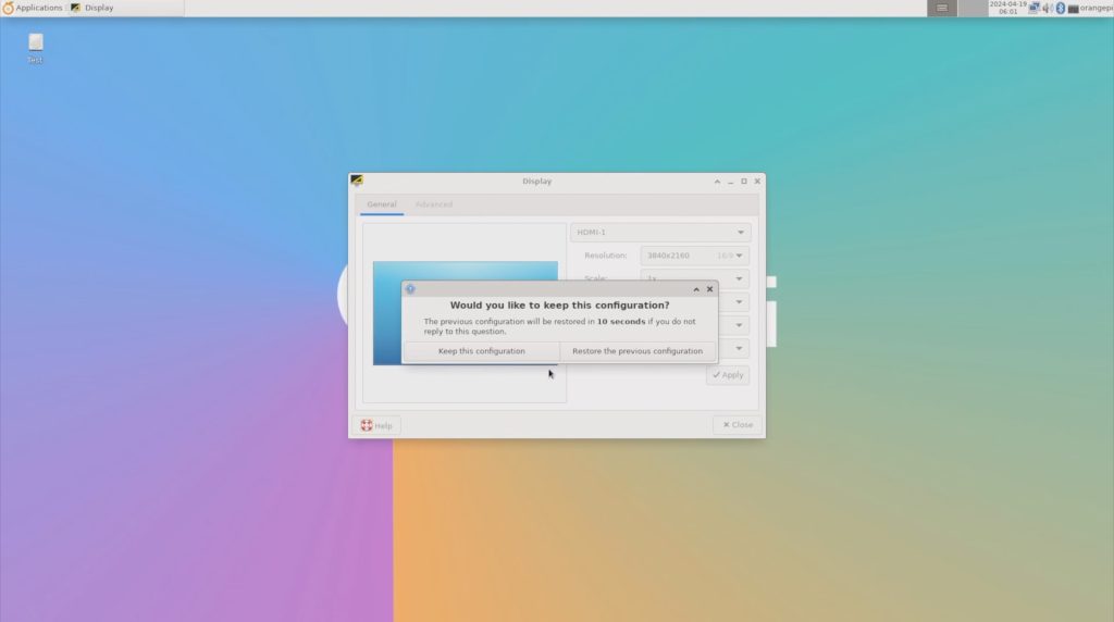
Now let’s step it up to 4K. There was a bit of weird behaviour when changing to 4K – the display wouldn’t refresh when the setting was applied and you could clearly see that the resolution hadn’t changed, although it indicated that it had. A reboot after changing the resolution setting seemed to fix the issue and it then booted up in 4K.

Now we can reopen the browser and Big Buck Bunny. We’ll set the playback resolution to 4K as well.

In 4K, playback gets off to a pretty poor start. We dropped a large number of frames in the beginning and continue to drop frames throughout playback. Opening up to full screen is even worse, to the point where it is basically unusable.

So this board does a fair bit worse at 4k playback than the Orange Pi 5 Plus. This is probably a software issue with the board using software decoding instead of hardware decoding. Opening up HTOP while the video playing back, the CPU is at about 40-50% utilisation across all cores which is a lot more than the 20-30% CPU utilisation on only 4 cores that we had on the 5 Plus playing back the same video.
To jump in here, if you’re going to be primarily using the Orange Pi 5 Pro as a media device then you’ll likely want to go with the Android image as this tends to perform better for video playback.
Sysbench CPU Benchmark
Next, let’s check the performance of the 5 Pro by running the Sysbench CPU benchmark.
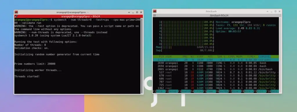
After 10 seconds we have processed a little under 5,350 events per seconds and we get a total score of 53,519. Over three tests, the Orange Pi 5 Pro managed an average of 53,520.
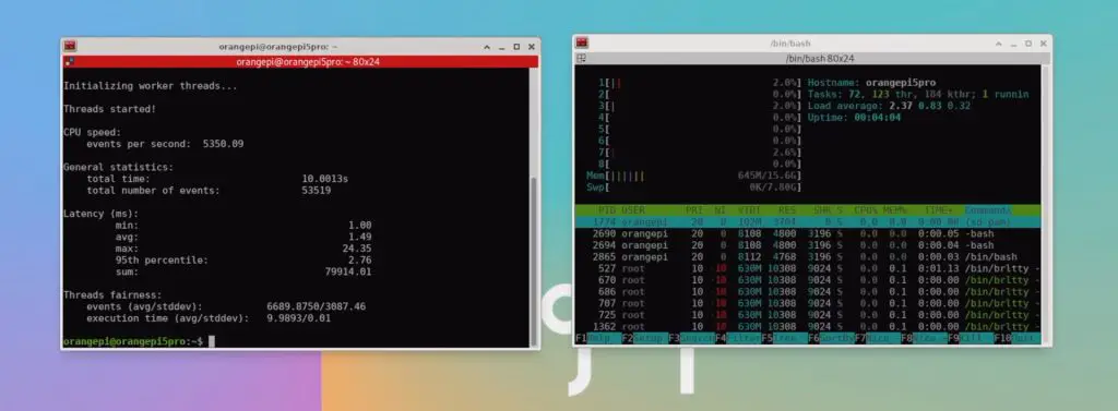
For comparison, and also over three consecutive tests;
- The Rock 5 B managed an average of 53,642
- The Khadas Edge 2 managed an average of 51,568
- The Orange Pi 5 Plus managed an average of 53,436
- The Raspberry Pi 5 manages an average of 35,000
So the results of the Orange Pi 5 Pro are a bit better than the Khadas Edge 2 with the same SOC. They’re actually very similar to the Rock 5 B and Orange Pi 5 Plus which have the better RK3588 CPU and they’re significantly higher than the Raspberry Pi 5, with an over 50% improvement.
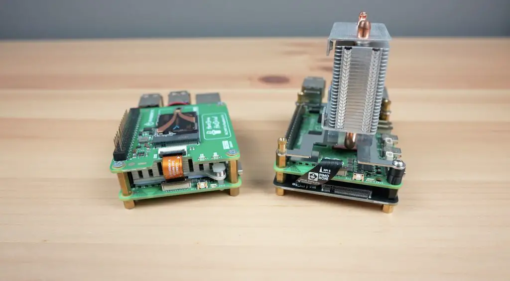
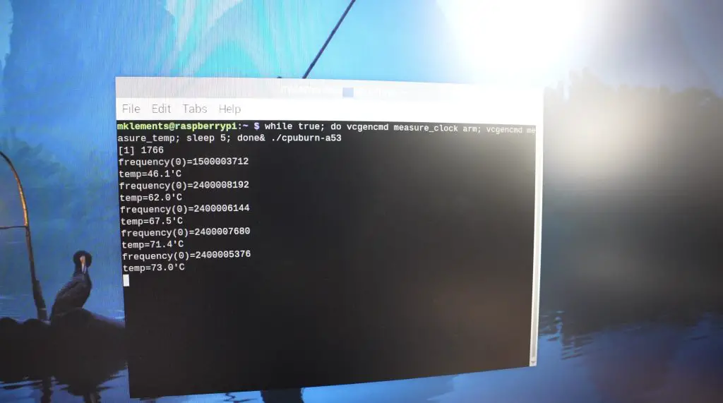
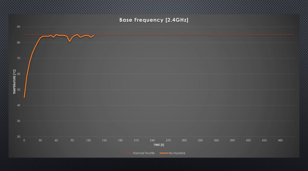
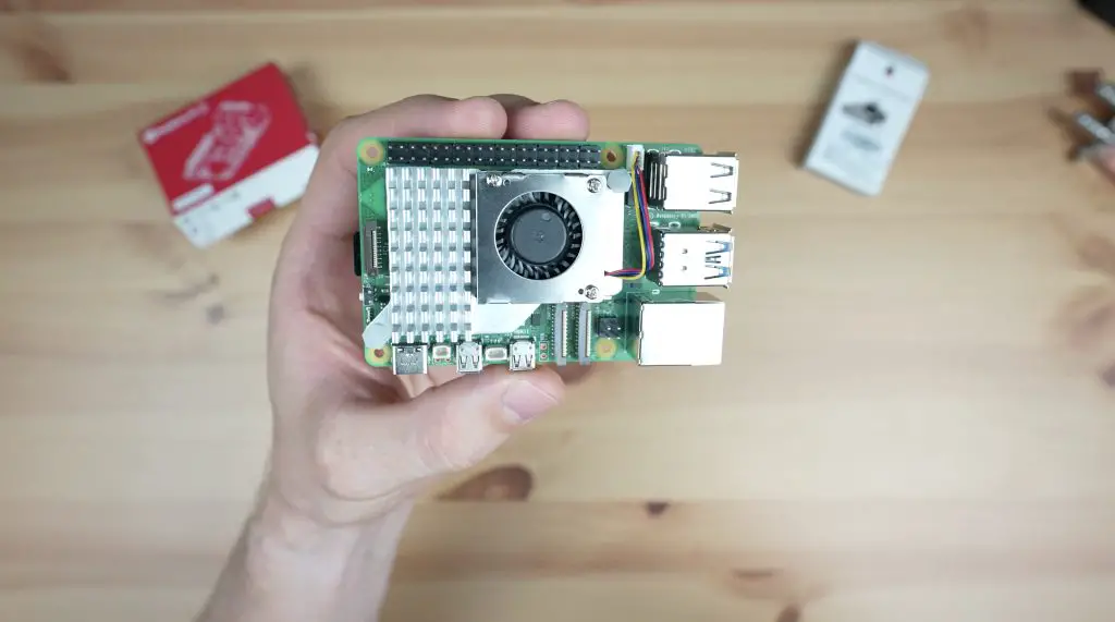
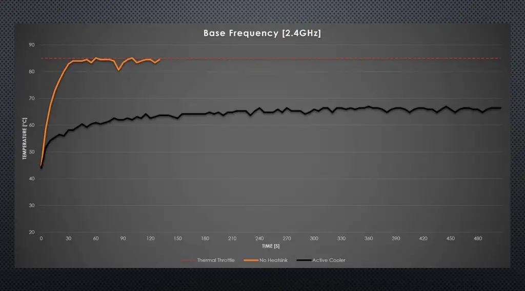
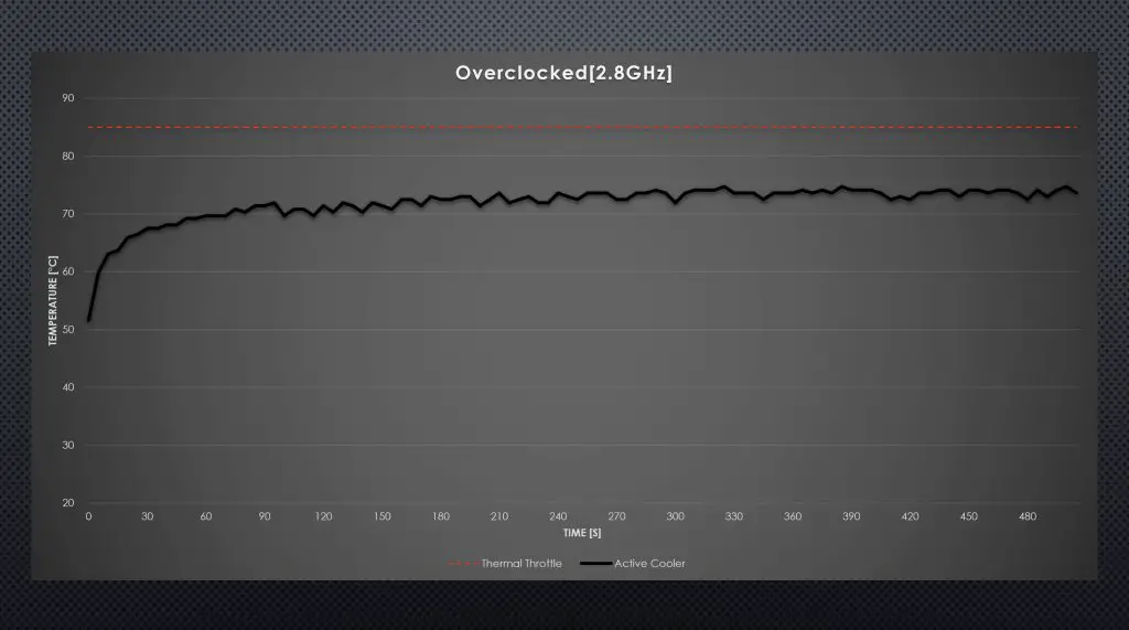
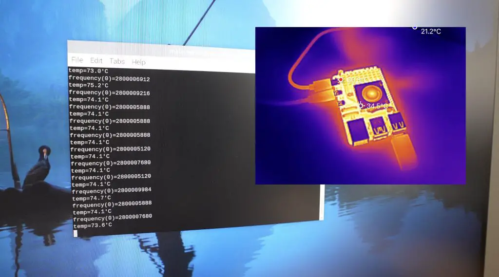
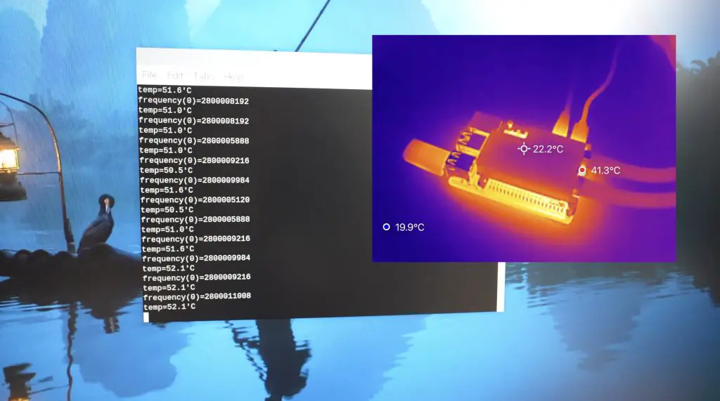
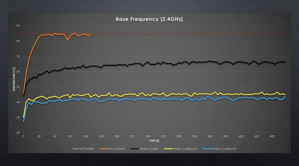
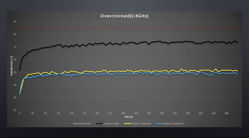
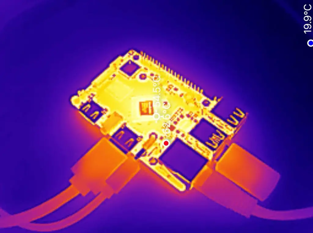
Thermally, you’ll probably need to use a heatsink on the CPU if you’re running CPU-intensive tasks. After playing back 4K video for around 15 minutes, the Orange Pi 5 Pro’s CPU was at over 70°C and the surface of the CPU was at 55°C. This was in a relatively cool room with an ambient temperature 20°C.

NVMe Drive Speed
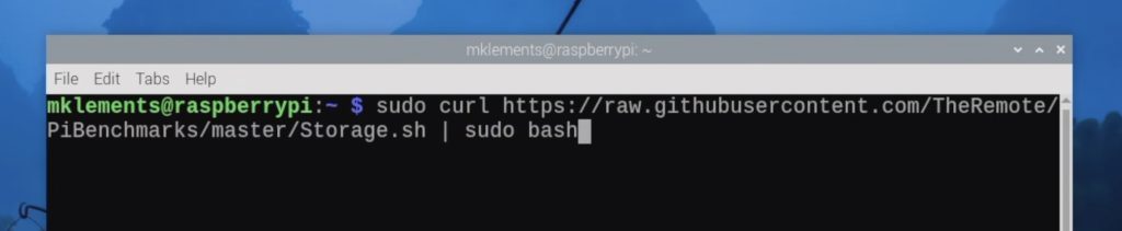
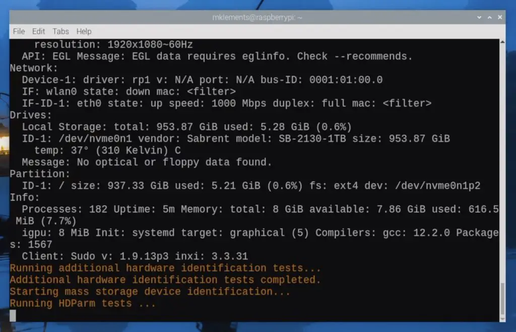
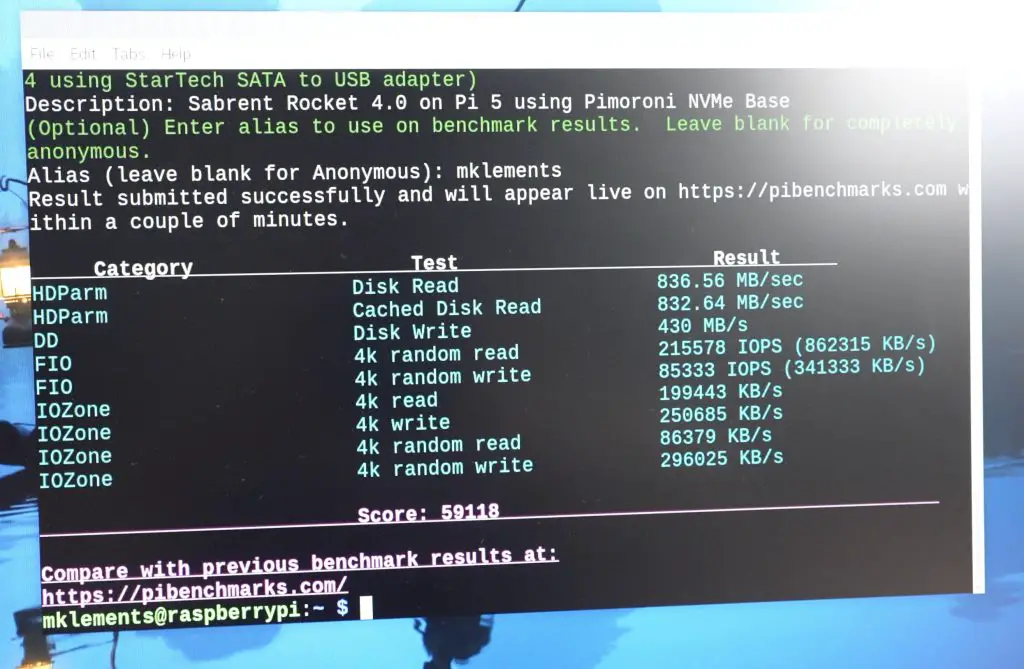
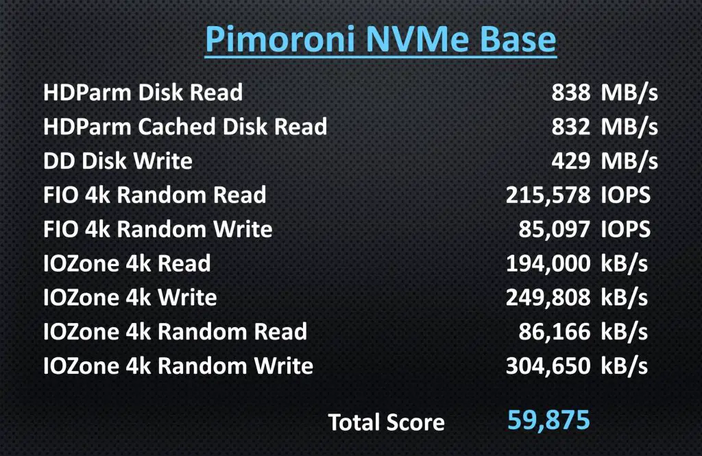
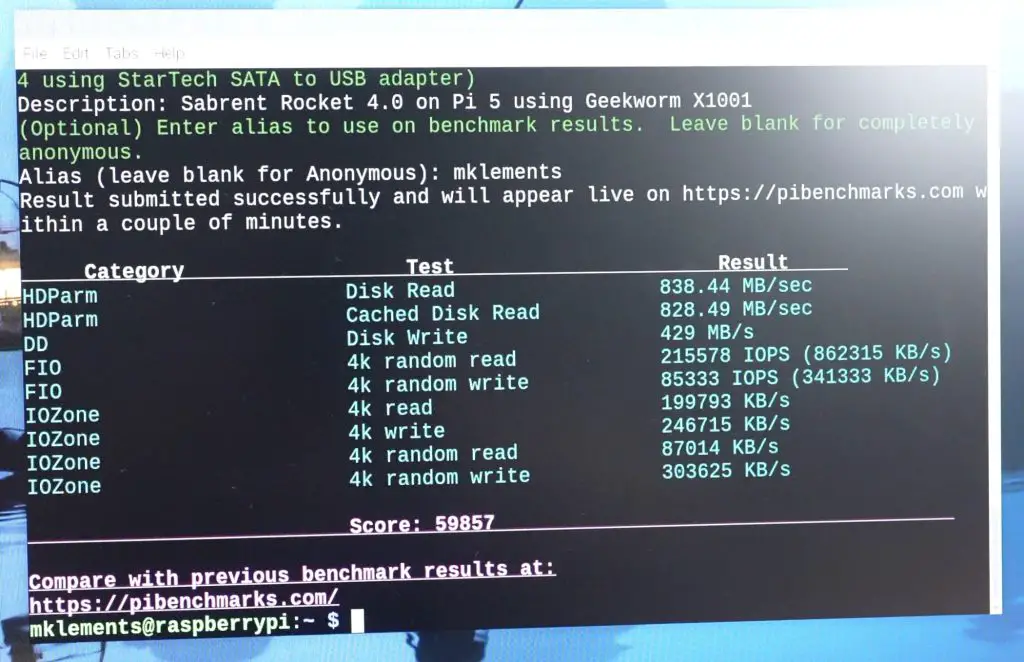
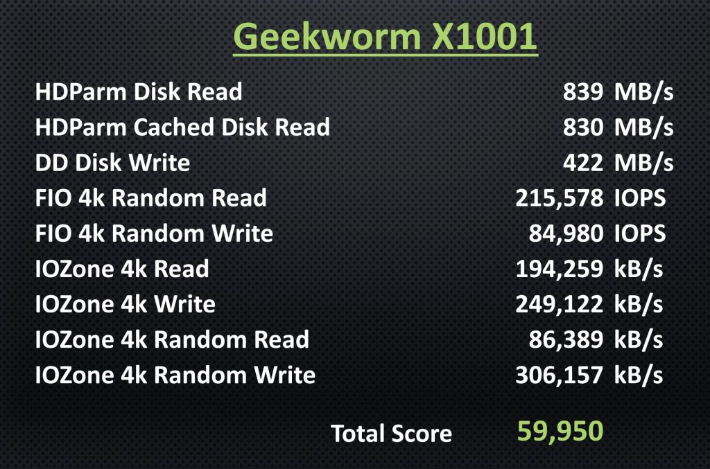
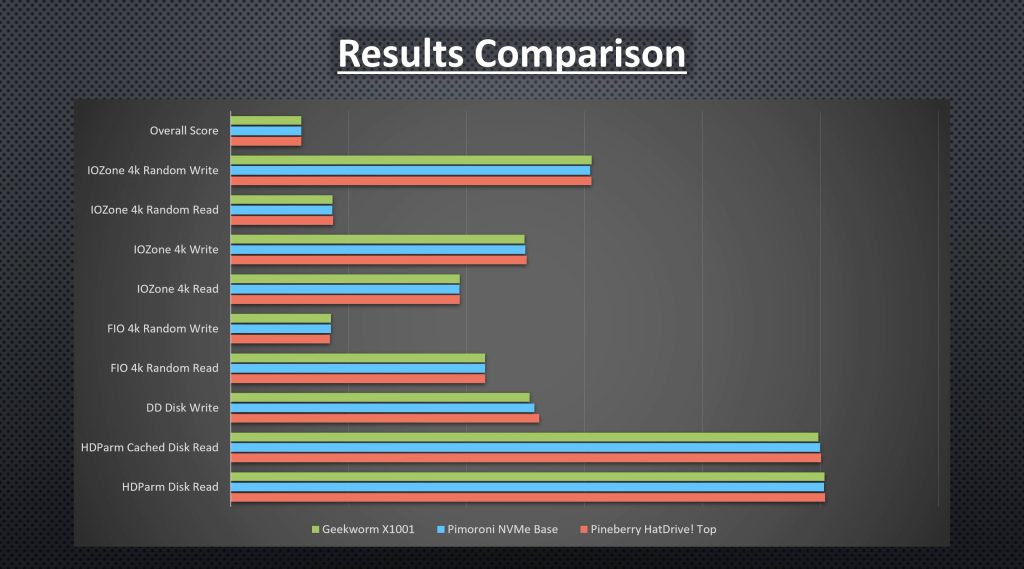
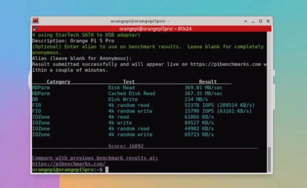
Next, let’s look at the NVME drive speed. For this test, I’m going to be using James Chambers PiBenchmarks script. I’ve used this script recently to benchmark a few different NVMe hats for the Raspberry Pi 5.
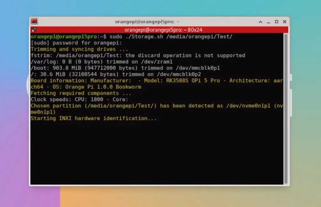
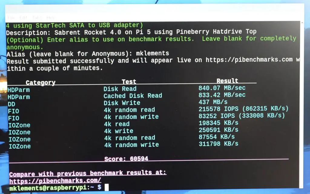
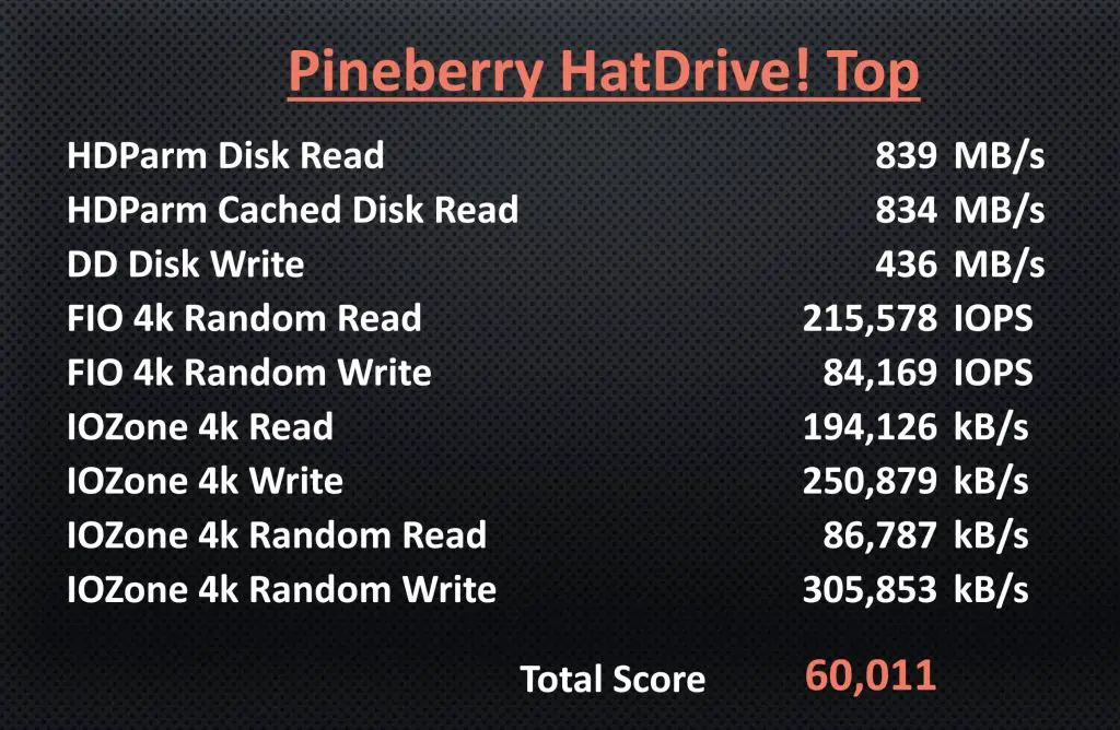
I ran the test three times, with very consistent results across the three tests and an average total score of a little over 16,000. The Pi 5 had results slightly under 60,000, so the Orange Pi 5 Pro is significantly slower than the Raspberry Pi 5, which is likely mainly due to the one-generation reduction on the PCIe port.
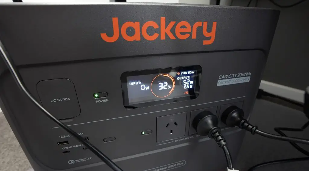
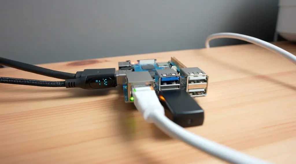
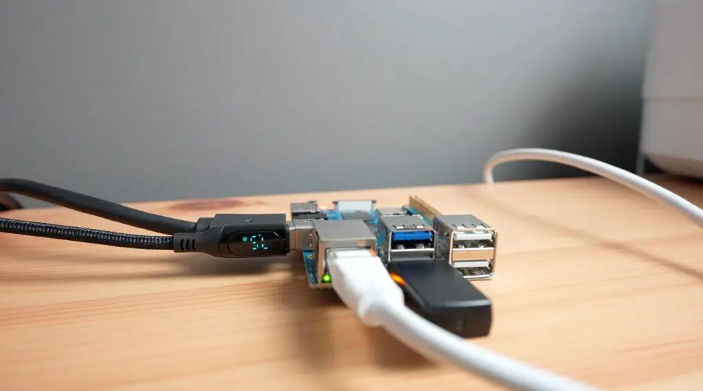
Power Consumption
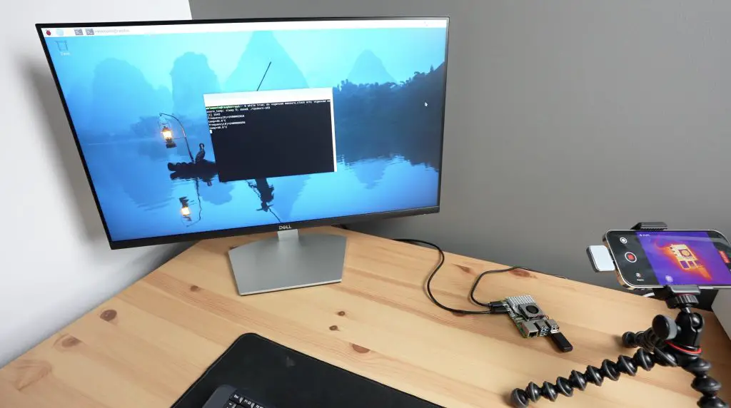
Lastly, let’s take a look at power consumption. To measure the 5 Pro’s power consumption, I used a USB power meter cable that supports power delivery.
This showed that the Orange Pi 5 Pro uses about 3w when idle and this goes up to 6-8w when loaded, with peaks of up to 9w. So fairly similar to the Raspberry Pi 5 and a bit more power-hungry than the Khadas Edge 2 with the same SOC.
Final Thoughts On The Orange Pi 5 Pro
In terms of cost, only the 16GB variant of the Pi 5 Pro is currently available at the time of writing this review, and it retails for $109. This is about $30 more than the best variant of Raspberry Pi, the 8GB version, but you’re getting double the RAM, double the CPU cores and onboard NVMe support which means you won’t need to buy an additional hat for it.
So, I think that the price is fair in terms of value for money.
Overall I think that the Orange Pi 5 Pro is a great alternative to the Raspberry Pi 5 if your project favours raw CPU or GPU performance – so for computationally intensive projects and simulations. It offers much better raw performance than the Raspberry Pi 5 and has a decent set of built-in IO.
It is limited by the single PCIe lane, so you don’t get two USB 3 ports, and the NVME drive is only running at gen 2 speeds. Depending on your project, this is might be something that you can live with.
The main reason why you’d want to get a Raspberry Pi 5 over the Orange Pi 5 Pro is for the software support. Orange Pi is one of the best-supported alternate SBC manufacturers, but even so, their community software support is quite far behind that of the Raspberry Pi 5. Raspberry Pi have fostered a large community around their products and this community is really good at working together to develop software and troubleshoot issues.
The Orange Pi 5 Pro is a great board if there is a software package or OS image built for it or if you have a good understanding of software and programming, but for the average hobbyist or tinkerer, if you’re trying a project that hasn’t been tried before, or you’re running a project that utilises the GPIO pins then you’re probably better off with the Raspberry Pi 5.
Let me know what you think of the Orange Pi 5 Pro in the comments section below and if you’ve got anything else that you’d like me to try run or test on it.