Having a look around on the internet, there are a few forums in which stepper motor control is discussed, however, none of them go into the detail required for an electronics newbie to be able to get their motor up and running with the hardware connections and the sketch. So here’s our complete step by step guide to get any Arduino to control a stepper motor.
Being able to control a stepper motor with your Arduino opens up a world of opportunity for new projects. Stepper motors offer precise control over their speed, position and direction so they are a popular choice for robotics, 3D printers, CNC projects and servo drive mechanisms.
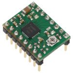
We will be using the Pololu range of stepper motor drivers as they are really cheap, easy to work with, offer simplistic control and are compatible with all of the Arduino development boards.
This project assumes you know the basics of Arduino programming, otherwise read our article on getting started with Arduino
What You Will Need To Control A Stepper Motor With Your Arduino
- Arduino (Uno Used Here) – Buy Here
- Power Supply (12V – 30W / 2.5A) – Buy Here
- Pololu Stepper Motor Driver
- Stepper Motor (1A or 2A To Match Driver) – Buy Here 1A, Buy Here 2A
- 100µF 12V Capacitor – Buy Here
How To Control Your Stepper Motor
First we will start by connecting the hardware together and then we will move on to the software/sketch. In this example we have used the same power supply to power the Arduino and the motor through the Pololu driver however these can be two separate power supplies.
Assemble The Components
You have two options when assembling the components, the first is to solder all of the connections to the Pololu motor controller and then solder the connections to the Arduino through a pin header and the second option is to solder pin headers onto the underside of the Pololu motor controller and then plug it into a breadboard to use jumpers to connect it to the Arduino. Use the soldered connections for a permanent installation or on something which is going to be moving around a lot and use the breadboard if you are just playing around with ideas on a bench.
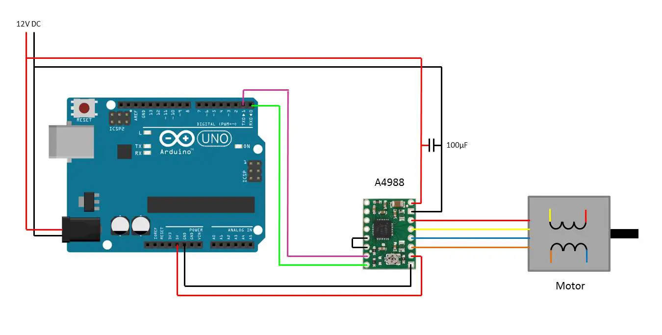
The basic circuit and connections to the Arduino and the Pololu driver are shown below, click to enlarge the image if required:
Connect the Pololu direction pin to Arduino pin 0 and the step pin to Arduino pin 1 as these are setup in the sketch. You can connect more than one motor to the Arduino by making simultaneous connections to any of the available pins.
Bridge the reset and sleep pins on the drive controller as we will not be using these.
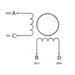
Your stepper motor should have four different coloured wires, these will be identified on your motors data sheet as shown below:
The wires work as pairs, one on each side of the opposing motor windings, in this case red and yellow form one pair and blue and orange form a second pair. These wires need to be connected in their pairs to the 1A and 1B and the 2A and 2B pins on the drive controller. It doesn’t matter which way around they are connected as long as one pair is connected to the 1 pins and the other pair to the 2 pins. Your motor may have different coloured wires so it is important to get the datasheet, alternately you can measure the resistance across wires with a multimeter, the pairs will have a resistance and the non pairs will show open circuit.
Setting The Driver Current Limit
Before running your motor, your need to set the current limit on your stepper motor driver, this is done by adjusting the small potentiometer on the driver. To do this, you’ll need to find your motors rated current per phase, which should be on the data sheet or in the product description. You’ll then need to set the driver’s maximum output current to be less than the motor rated current to avoid burning the motor out.
Next you’ll need to find your motor driver’s Vref equation, this is also available on the datasheet or in the product description. You need to input your motors rated current into the Vref equation to get your required Vref voltage.
Now power up your Arduino and motor driver and measure the actual Vref, this is typically done between GND and the Vref measurement point denoted as a white dot on the board or alternatively between GND and the metal top of the potentiometer. Adjust the potentiometer until the actual Vref matches the required Vref you have calculated.
You can also calculate your Vref using a slightly lower current to avoid over stressing the motor and producing excess heat.
Choosing Different Components
Choosing A Different Stepper Motor
Depending on your application, you may require a bigger or smaller stepper motor. Stepper motors are generally sized by their output torque, you will need to figure our, either through experimentation or through calculations how much torque you require. You can then select a motor which can produce your required torque, the data sheet will then tell you the required current and then you can select a motor controller to suite.
Sizing the Stepper Motor Driver
The drive controller used in this example, the A4988 can drive a motor up to 1A and the second controller mentioned in the parts list, the DRV8825 can drive a motor up to 2A. Pololu make a number of stepper motor drive controllers (shown here) for different size motors, it is just important that you have a controller which can produce more current than the motor requires otherwise it will burn out.
Upload The Sketch
Now you can upload your sketch onto your Arduino, if you haven’t uploaded a sketch before then follow this guide on getting started.
// Stepper Motor
// Michael Klements
// The DIY Life
// 25/01/2017

int motorPin = 1;        //Assign pin numbers
int dirPin = 0;
int motorDir = 0;        //Assign the initial motor direction
int motorSpe = 500;      //Assign the motor speed, a smaller number is a faster speed (shorter delay between pulses)
int rotation = 1000;     //Assign the motor rotation in pulses

void setup()
{
  pinMode(motorPin, OUTPUT);  //Assign Pins
  pinMode(dirPin, OUTPUT);
}

void loop()
{
    if(motorDir==0)    //Set the motor direction
    {
      digitalWrite(dirPin, LOW);
    }
    else
    {
      digitalWrite(dirPin, HIGH);
    }
    for(int j = 0 ; j <= rotation ; j++)  //Run the motor to the input rotation at the input speed.
    {
      digitalWrite(motorPin, HIGH);
      delay(motorSpe);
      digitalWrite(motorPin, LOW);
    }
    if(motorDir==0)    //Change the motor direction at the end of the rotation travelled
    {
      motorDir=1;
    }
    else
    {
      motorDir=0;
    }
}
Here is the link to download the steppermotor code.
The sketch starts by assigning the motor and direction pins in the setup function as declared in the created variables.
The Arduino then continuously runs through the loop code which will turn the motor in one direction a certain number of pulses (rotation angle) and at a certain speed before reversing and running in the opposite direction at the same speed and number of pulses.
Changing The Motor Speed, Number Of Rotations And Direction
There are three parameters in the sketch which can be modified to produce your desired motor output, these are the speed at which the motor rotates, the total angle of rotation or number of rotations traveled and finally the motor direction.
We will start with the speed. The motor speed is determined by how long the Arduino waits between consecutive pulses. The speed is set in row 9 under the variable motorSpe and represents the time in milliseconds between pulses. The shorter the time between pulses, the faster the motor will turn. This has its limitations though, both through the motor and the controller. You should be able to lower this value to about 100 milliseconds without any issues, if the motor starts humming, skipping around or moving erratically then the pulse speed is likely too fast and should be slowed down.
The second parameter is the rotation angle or number of rotations. Stepper motors have a certain number of steps per revolution or poles, this figure is used to determine how many degrees or turns the motor will make. The number of pulses in defined in row 10 under the rotation variable. It is currently set at 1000 pulses which means that on a 200 step per revolution motor, the motor will make 5 complete turns. This can be adjusted as high or low as necessary for your project. If we had set the rotation to 20, then the motor would move 20 steps which corresponds to 20/200ths of a full rotation or 18 degrees.
The final parameter is the rotation direction which is defined in row 8 and is set on the drive controller in rows 20-27. Setting the direction output pin HIGH will rotate the motor in one direction and LOW will rotate the other direction.
If you’re looking for a project in which you can use your stepper motor controller, have a look at our solar tracker project, it utilises a linear actuator which can be stepper motor controllers to precisely position a solar array such that it is always in direct sunlight.
Did you find this guide helpful? Were you able to control and run a stepper motor? Let us know in the comments section below.
Have a look at our other Arduino projects here.


I really love this tutorial and finally got my stepper motor to run at a speed that I can control. I have been trying to get to grips with the Arduino concepts for quite a while now, and this has given me the push.
I used the example as above in this tutorial:
Arduino Stepper Motor Control, Using Pololu Driver
however I used a 35V 100uF cap, because that’s all I had lying around.
I’m powering the Pololu Stepper Motor Driver board with a 12V battery and the Arduino board with a 1A 12V power supply.
My A4988 board gets very hot, very quickly, to the point that I’m afraid that it might burn out.
Any ideas what I can do to make it run at ambient Temperature ?
Thanks in advance…
Oliver.
Hi Oliver,
Thanks for the great feedback! If your board is getting hot, you may want to stick a heat sink onto it. Have a look at your local electronics store or online, you get small “peel and stick” heat sinks made specifically for small chips like these. That should help keep it cool.
Good Luck!
Just a quick comment. I am new to this and have read many articles and one point that is made on many sites is that the current needs to be adjusted on these board before using or you will burn them out.
The little trim pot on the board is for that purpose. Search and you will find a technique.
Hi Robin,
Thanks for your comment, this is quite an important part which has been left out. I have added a section on setting up the current limit on your driver as per your suggestion. Good luck with your project!
Can you make sketch for H-Bridge pure sine wave inverter?
i accidentally found this site and after reading it learned more in an hour than i have all week tomorrow i am going to proceed further using your info i am 75yrs off age so a bit slow will keep in touch
len williams
cardiff
ps thanks
That’s great, good luck with your project!